1
Carafe User's Manual
Release Alpha.5
Alvin Jee
David Dahle
Cyrus Bazeghi
F. Joel Ferguson
UCSC-CRL-96-05
January 24, 1996
Board of Studies in Computer Engineering
University of California, Santa Cruz
Santa Cruz, CA 95064
c Regents of the University of California
Copyright abstract
This document describes the command line user interface and the X window
user interface for Carafe, the second generation Inductive Fault Analysis (IFA)
program. This document also describes the Hemlock version of Carafe used for
extracting faults in the interconnect regions of standard cell designs. The syntax of
all the commands and their parameters are described in this document along with
a description of the formats of the various les used and created by Carafe.
CONTENTS
1
Contents
1. An Introduction to Carafe
1.1 Major Changes from the Previous Version
1.2 Acknowledgments : : : : : : : : : : : : : :
4
: : : : : : : : : : : : : : : : : : :
: : : : : : : : : : : : : : : : : : :
2. Installing Carafe
2.1 Tested Platforms : : : : : : : :
2.2 Installation Steps : : : : : : : :
2.3 Carafe Environment Variables :
7
: : : : : : : : : : : : : : : : : : : : : : : : :
: : : : : : : : : : : : : : : : : : : : : : : : :
: : : : : : : : : : : : : : : : : : : : : : : : :
3. Tutorial
4.1 Compound Faults : : : : : : : : : : :
4.1.1 Overview : : : : : : : : : : :
4.1.2 Space/Time Considerations :
4.2 Bridges : : : : : : : : : : : : : : : :
4.2.1 Critical Area Calculation : :
4.2.2 Limitations : : : : : : : : : :
4.3 Breaks : : : : : : : : : : : : : : : : :
4.3.1 Critical Area Calculation : :
4.3.2 Limitations : : : : : : : : : :
4.3.3 Output Files : : : : : : : : :
4.4 Transistor Gate Bridge/Break Faults
4.4.1 Critical Area Calculation : :
4.4.2 Limitations : : : : : : : : : :
4.5 Gate Oxide Short Faults : : : : : : :
4.5.1 Critical Area Calculation : :
4.5.2 Limitations : : : : : : : : : :
14
: : : : : : : : : : : : : : : : : : : : : :
: : : : : : : : : : : : : : : : : : : : : :
: : : : : : : : : : : : : : : : : : : : : :
: : : : : : : : : : : : : : : : : : : : : :
: : : : : : : : : : : : : : : : : : : : : :
: : : : : : : : : : : : : : : : : : : : : :
: : : : : : : : : : : : : : : : : : : : : :
: : : : : : : : : : : : : : : : : : : : : :
: : : : : : : : : : : : : : : : : : : : : :
: : : : : : : : : : : : : : : : : : : : : :
: : : : : : : : : : : : : : : : : : : : : :
: : : : : : : : : : : : : : : : : : : : : :
: : : : : : : : : : : : : : : : : : : : : :
: : : : : : : : : : : : : : : : : : : : : :
: : : : : : : : : : : : : : : : : : : : : :
: : : : : : : : : : : : : : : : : : : : : :
5. Circuit Extraction
14
14
15
15
16
18
18
20
22
25
25
25
25
26
26
27
28
: : : : : : : : : : : : : : : : : : : : : : : : : : : : : : : : :
: : : : : : : : : : : : : : : : : : : : : : : : : : : : : : : : :
6. Customizing Carafe
6.1
6.2
6.3
6.4
7
7
8
9
4. Explanation of Faults
5.1 Electrical Nodes
5.2 Transistors : : :
5
5
How Carafe works : : : : : : : :
Technology File : : : : : : : : : :
Fabrication File : : : : : : : : : :
Library Description File Format
28
28
31
: : : : : : : : : : : : : : : : : : : : : : : :
: : : : : : : : : : : : : : : : : : : : : : : :
: : : : : : : : : : : : : : : : : : : : : : : :
: : : : : : : : : : : : : : : : : : : : : : : :
31
31
35
38
2
CONTENTS
7. Running Carafe
7.1 Invoking Carafe : : :
7.2 Carafe Option Flags
7.3 Outputs : : : : : : :
41
: : : : : : : : : : : : : : : : : : : : : : : : : : : : : : :
: : : : : : : : : : : : : : : : : : : : : : : : : : : : : : :
: : : : : : : : : : : : : : : : : : : : : : : : : : : : : : :
8. Carafe Command Line Interface
8.1
8.2
8.3
8.4
8.5
8.6
8.7
8.8
8.9
8.10
8.11
8.12
8.13
ca : : :
extract :
at : : :
help : :
info : : :
list : : :
quit : :
read : :
set : : :
shell : :
source :
time : :
write : :
: : : : : : : : : : : : : : : : : : : : : : : : : : : : : : : : : : : : : :
: : : : : : : : : : : : : : : : : : : : : : : : : : : : : : : : : : : : : :
: : : : : : : : : : : : : : : : : : : : : : : : : : : : : : : : : : : : : :
: : : : : : : : : : : : : : : : : : : : : : : : : : : : : : : : : : : : : :
: : : : : : : : : : : : : : : : : : : : : : : : : : : : : : : : : : : : : :
: : : : : : : : : : : : : : : : : : : : : : : : : : : : : : : : : : : : : :
: : : : : : : : : : : : : : : : : : : : : : : : : : : : : : : : : : : : : :
: : : : : : : : : : : : : : : : : : : : : : : : : : : : : : : : : : : : : :
: : : : : : : : : : : : : : : : : : : : : : : : : : : : : : : : : : : : : :
: : : : : : : : : : : : : : : : : : : : : : : : : : : : : : : : : : : : : :
: : : : : : : : : : : : : : : : : : : : : : : : : : : : : : : : : : : : : :
: : : : : : : : : : : : : : : : : : : : : : : : : : : : : : : : : : : : : :
: : : : : : : : : : : : : : : : : : : : : : : : : : : : : : : : : : : : : :
9. Carafe X Window Interface
9.1
9.2
9.3
9.4
File Menu : : : : :
Commands : : : :
View : : : : : : : :
Interface Controls :
: : : : : : : : : : : : : : : : : : : : : : : : : : : : : : : :
: : : : : : : : : : : : : : : : : : : : : : : : : : : : : : : :
: : : : : : : : : : : : : : : : : : : : : : : : : : : : : : : :
: : : : : : : : : : : : : : : : : : : : : : : : : : : : : : : :
10.Hemlock
10.1
10.2
10.3
10.4
Installing : : : : :
Running Hemlock :
Inputs : : : : : : :
Outputs : : : : : :
: : : : : : : : : : : : : : : : : : : : : : : : : : : : : : : :
: : : : : : : : : : : : : : : : : : : : : : : : : : : : : : : :
: : : : : : : : : : : : : : : : : : : : : : : : : : : : : : : :
: : : : : : : : : : : : : : : : : : : : : : : : : : : : : : : :
Alpha-Alpha.1 : : :
Alpha.1-Alpha.2 : :
Alpha.2-Alpha.3 : :
Alpha.3-Alpha.3.1 :
Alpha.3.1-Alpha.3.2
Alpha.3.2-Alpha.4 :
Alpha.4-Alpha.5 : :
B. .bridger File Format
C. .ccshort File Format
44
44
45
46
46
46
47
47
48
48
51
51
52
52
54
54
56
57
60
61
A. Revision History
A.1
A.2
A.3
A.4
A.5
A.6
A.7
41
41
42
61
61
61
62
63
: : : : : : : : : : : : : : : : : : : : : : : : : : : : : : :
: : : : : : : : : : : : : : : : : : : : : : : : : : : : : : :
: : : : : : : : : : : : : : : : : : : : : : : : : : : : : : :
: : : : : : : : : : : : : : : : : : : : : : : : : : : : : : :
: : : : : : : : : : : : : : : : : : : : : : : : : : : : : : :
: : : : : : : : : : : : : : : : : : : : : : : : : : : : : : :
: : : : : : : : : : : : : : : : : : : : : : : : : : : : : : :
63
63
63
64
64
65
65
67
68
CONTENTS
D. FABIT
E. .gateBreaks File Format
F. .gateBridge File Format
G. .graph File Format
H. .loc File Format
I. .mag File Format
J. .pro File Format
K. .sim File Format
L. .src File Format
M. .tdl File Format
References
3
69
71
72
73
78
79
82
84
88
89
91
4
1. An Introduction to Carafe
1. An Introduction to Carafe
Inductive Fault Analysis (IFA) is a procedure that determines the failures that can
occur in a circuit due to the presence of a spot defect[SMF85]. Carafe bloats and shrinks
conducting lines and nds the intersection of conductors in dierent planes to determine
how a layout is aected by spot defects. Since the list of faults is generated based on the
layout of the circuit, only the realistically possible faults are reported. The rst software to
implement the defect simulation phase of IFA determined that over 99% of the spot defects
caused either a bridge or a break fault to occur. Since virtually all spot defects are manifest
as bridge or break faults, we can avoid the costly defect simulation and directly extract the
realistically possible bridge and break faults from the circuit layout. Carafe is the second
generation IFA software designed to explicitly extract the bridge, break, gate oxide short
(GOS), and transistor gate bridge/break faults that may be caused by spot defects using
the layout of the circuit and given defect parameters.
The faults that are found by Carafe are modeled, for switch-level simulation purposes,
as extra transistors inserted into the extracted netlist of the circuit. The resulting netlist
can then be simulated to determine the eect of each fault. For more accurate circuit
simulation, the fault transistors can be replaced with resistors and a circuit simulator, such
as SPICE, can be used. Furthermore, the list of faults found by Carafe is ordered in a list
by the likelihood of occurrence of the faults relative to each other. Fault simulation can be
used with the fault likelihoods to estimate the defect coverage of any given test set.
Since the primary goal of testing integrated circuits (ICs) is to ensure that as few
defective ICs are shipped as possible, a test method that insures a very high percentage
of defect coverage is needed [WB81] [MAJC92]. However, many of the defects that occur
during the fabrication of CMOS ICs do not exhibit traditional fault behavior. To obtain
higher levels of defect coverage test sets can be generated to target the faults caused by
defects during fabrication. The purpose of Carafe is to indicate which faults are likely to
occur so that they may be targeted by tests.
Unlike what is assumed by traditional stuck-at fault models, CMOS IC defects may not
be stuck at a certain logic value [GCV80] [SMF85]. The stuck-at fault model does not take
into account the actual circuit fault and thus often does not model the resulting behavior
of many circuit faults. A better way to generate tests is to rst locate the circuit faults
that can occur in the circuit, determine the behavior of those circuit faults, and then derive
tests that target these behaviors. Inductive Fault Analysis is a procedure that provides the
list of circuit faults that can occur in a given physical implementation of the circuit [Fer87].
Carafe has been implemented using about 45,000 lines of C code. Carafe has been
designed to be technology independent and can thus be used for a variety of CMOS fabrication technologies. Provisions are made to accommodate any discrete defect distribution
functions by layer and defect size [JF93].
This manual is organized in a way to be both a tutorial for rst time users and as
a reference source for more advanced users. Here is a list of the chapters with a short
description of what they contain.
Introduction This chapter. A basic hello, welcome to Carafe.
Installing Carafe A step by step installation procedure for Carafe. Contains information
on tested platforms, compilers, and environment variables.
1.1. Major Changes from the Previous Version
5
Tutorial A short but complete tutorial on how to setup and use Carafe. Covers such things
as loading a le, extracting faults, viewing faults, and manipulating the image.
Explanation of Faults Gives an overview of compound fault extraction and an explanation of bridge, break, gate oxide short (GOS), and transistor gate bridge/break
faults.
Circuit Extraction Describes the important details of Carafe's circuit extractor and indicates potential pitfalls.
Customizing Carafe Gives a description of how Carafe works and what it does. Information on how to create fabrication statistics les, technology les, and library les
is given along with complete descriptions of each le type.
Running Carafe Gives information on how to run both the command line version and
the X Window version of Carafe, including option ags and their descriptions.
Carafe Command Line Interface Gives a description of all the Carafe commands for
the command line interface.
Carafe X Window Interface Shows the various screens and menus of the X Window
version of Carafe and how to use them.
Hemlock Gives a description of the Hemlock version of Carafe, which employs who levels
of hierarchy for circuits composed of standard cells.
Appendix Descriptions of various le types used by Carafe.
1.1 Major Changes from the Previous Version
Compound Faults Carafe can now extract compound bridge and break faults that are
capable of simultaneously bridging or breaking an arbitrarily large number of circuit
elements, depending on the defect size.
New Fault Types Carafe can now extract transistor gate bridge/break faults from circuit
layouts.
Fault Visualization Carafe now displays faults using the critical area of the fault instead
of the more abstract length-widths. These critical areas can be viewed by defect size
and layer.
1.2 Acknowledgments
Carafe is a product of the eorts of many people guided by Professor F. Joel Ferguson
at the University of California, Santa Cruz. The precursor of Carafe is the FXT inductive
fault analysis program written by F. Joel Ferguson. The overall design and a large portion
of the implementation of Carafe was done by Alvin Jee. The tile based data structures of
the Magic layout tool were customized for Carafe by George Riusaki. Alan Smith created
the early versions of the X Windows/Motif graphical user interface. Cyrus Bazeghi added
the gate oxide short fault extractor to Carafe. Mark Fitzpatrick performed initial work on
the break fault extractor and Je Rogenski developed the present break fault extractor.
David Dahle added compound fault extraction, transistor gate bridge/break faults, and
fault visualization by critical area.
This work has been sponsored by the ne folks at Semiconductor Research Corporation,
National Science Foundation, Hewlett-Packard, and Intel.
6
1. An Introduction to Carafe
Many others have contributed to the Carafe project by oering suggestions for improving
algorithms and the user interface design and by testing and debugging Carafe. Many
thanks go to Brian Chess, Tony Freitas, Haluk Konuk, Professor Tracy Larrabee, Richard
McGowen, Je Rearick, Andy Rosenbaum, Carl Roth, Joe Russack, Darren Senn, David
Staepalaere, Martin Taylor, Jon Colburn, Chris Manlove, Paul Imthurn, Alan Waterman
and a whole bunch of other people too numerous to list.
7
2. Installing Carafe
Carafe has been written in ANSI C and should compile and run on most UNIX platforms.
Carafe has been successfully compiled with both GCC and CC on a variety of platforms.
2.1 Tested Platforms
The command line based version of Carafe has been tested on the following machines:
Linux
Sun-4
SPARCstation 1+
SPARCstation 2
SPARCstation 20
MIPS SGI IRIX 5.3
NeXTSTEP for Motorola and Intel Processors
IBM RS6000 POWERserver 350 running AIX 3.2.5
DEC Alpha 3000/600 running OSF/1 V3.0
DEC Alphastation 250 4/266 running OSF/1 V3.2
The Motif-based graphical user interface should work with Motif version 1.1 or later, and
has been tested on the following machines:
Sun-4
SPARCstation 20
MIPS SGI IRIX 5.3
Linux (MetroLink Motif 2.0)
IBM RS6000 POWERserver 350 running AIX 3.2.5
DEC Alpha 3000/600 running OSF/1 V3.0
DEC Alphastation 250 4/266 running OSF/1 V3.2
2.2 Installation Steps
Once the EncryptedCarafe le and the key are obtained, follow the installation steps
given below:
1. Move the EncryptedCarafe le to the directory in which the Carafe directory is to
be placed.
2. Unencrypt the le with the UNIX crypt command using the acquired key. The syntax
is: crypt key < EncryptedCarafe > carafe.tar.gz
3. Uncompress the le carafe.tar.gz using the GNU tar command. The syntax is: tar
-xzvf carafe.tar.gz.
4. Enter the carafe directory. Check the README le for any last minute information.
Carafe uses an automatically generated script to congure Carafe for the target
machine. This script performs tests to determine the settings of various ags and
then generates Makeles based on those ags. Read the INSTALL le for detailed
instructions on compiling and installing Carafe.
8
2. Installing Carafe
2.3 Carafe Environment Variables
The Carafe program must have both a technology le and a fabrication defects statistics
le in order to run. The default les used for the technology and fabrication defect statistics
are carafe.tech and carafe.fab in the current directory unless modied through the
option ags given in the Carafe Option Flags section. It is sometimes not desirable to
have copies of the two les in every directory in which Carafe is to be used. Rather than
using the option ags to specify the locations of these les every time, Carafe checks the
environment variables for the location of these les. The following are the environment
variables that Carafe checks:
CARAFE TECH This variable indicates the directory and le name to use
for the technology le if the default le carafe.tech is not in the current
directory and no le was specied with the '-t' option.
CARAFE FAB This variable indicates the directory and le name to use for
the fabrication defect statistics le if the default le carafe.fab is not in
the current directory and no le was specied with the '-f' option.
CARAFE LIB The Hemlock version of Carafe requires a description of all the
standard cells to be used. This environment variable species which le to
use as the standard cell description le.
CARAFE DSTYLE This species the drawing style le that Carafe uses to
determine how the dierent layers of material are drawn. This le has the
same format as the dstyle le from the Berkeley Magic program. The dstyle
le can also be specied using the command line option. Carafe comes
with a sample dstyle le called carafe.dstyle located in the carafe/lib
directory.
CARAFE COLORMAP This environment variable species the le that
contains color map information. This information is used with the dstyle
information to determine how layout geometries are displayed in the graphical user interface. Carafe comes with a sample colormap le carafe.cmap
located in the carafe/lib directory.
CARAFE CELLPATH This environment variable species the paths for
subcells. If the subcells are not in the current directory Carafe will search
for them in these listed directories. The format for the value string is:
/usr/lib:/joe/les/subcells:/project/bin/cells
Check the operating system manuals for setting the environment variables. On most
systems, the command:
% setenv VARIABLE NAME value
will set the environment variable named VARIABLE NAME to value. Since these variables
need to be set every time the user logs on, the setenv lines should be placed in a startup
le.
Carafe should now be set up and ready to run!
9
3. Tutorial
This chapter contains a step by step walk through of a typical Carafe X Window session.
Starting with setting up environment variables, through loading a sample le provided with
Carafe and selecting extract options, to viewing the results, this chapter seeks to give a rst
time user a quick overview of how to use Carafe. This tutorial is based on a session run on
a Sun-4 running SunOS 4.1.3.
Setting up the environment
For Carafe to run correctly certain les are required. Keeping these conguration les in
the current working directory at all times can become cumbersome. To allow a user to put
the conguration les all in one place and execute Carafe elsewhere, environment variables
are used.
These are the environment variables used by Carafe:
CARAFE TECH
CARAFE FAB
CARAFE DSTYLE
CARAFE COLORMAP
For a description of these environment variables please read the Carafe Environment
Variables section in the Installing Carafe chapter.
To set up these environment variables type the following:
setenv CARAFE TECH path/carafe/lib/carafe.tech
setenv CARAFE FAB path/carafe/lib/carafe.fab
setenv CARAFE DSTYLE path/carafe/lib/carafe.dstyle
setenv CARAFE COLORMAP path/carafe/lib/carafe.cmap
where path is the path to the Carafe directory. Note: These variables need to be set each
time a user logs on.
Running Carafe
Now that Carafe is congured correctly go to the carafe/sample directory and type:
carafe
Carafe should now display a message similar to this:
Using technology: scmos
Using scmos fabrication statistics.
Welcome to Carafe - Version Alpha.5
Last updated on Thu Nov 9 12:28:08 PST 1995
Copyright (C) 1990-1995 Regents of the University of California
10
3. Tutorial
The Carafe graphical interface window should also appear. If Carafe does not load and
a "command not found" or equivalent message is displayed then check to see that Carafe
is in your path statement and has been installed correctly.
Loading a le
Use the mouse to select the File menu item. From the drop down menu select Open....
The Open File window should now pop up. Select the le 1bit.strm from the Files box
and then press in the OK button.
Carafe should now display the le 1bit.strm graphically on the screen. The le
1bit.strm is a cell for a 1 bit full adder.
Use the left mouse button to box an area to zoom in on. The right mouse button is used
for centering the display about a selected point. The bottom three buttons can be used to
zoom out all the way, zoom in, and zoom out respectively. Play around with zooming in
and out using the mouse and the zoom buttons.
Extracting Faults
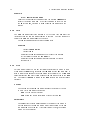
Now that a le has been successfully loaded, fault extraction can be done. Select
Commands from the menu bar. From the drop-down menu select Extract.... A popup window of extract options should now appear. Note the various options for extraction.
The Extract window is comprised of ve sections: Extract Options, Bridges, Breaks,
Faults, and Output Files. For a detailed description of each of these please, refer to the
Carafe X Window Interface chapter.
For this example, leave the selections in their default setting and press the Extract
button. Carafe will change the mouse pointer to a watch while it works. Once the mouse
pointer returns to the cross hair the extraction is nished. Refer to the window from which
Carafe was started. This window gives you a log of all that Carafe has done. The window
should display something similar to this:
arapaho:[/tst/carafe/sample/1bit] % ../../src/carafe
Using technology: scmos
Using scmos fabrication statistics.
Welcome to Carafe - Version Alpha.5 PR1.2
Last updated on Thu Dec 21 01:05:32 PST 1995
Copyright (C) 1990-1995 Regents of the University of California
Reading Calma format file: /tst/carafe/sample/1bit/1bit.strm
Library was written in GDS II version 3
Reading library 1bit
Reading structure 1bit
Flattening auto flat cells.
Making composites.
Connecting contacts.
Cell 1bit complete
Extracting transistor regions.
11
Extracting node regions.
Assigning node labels.
Extracting gate oxide shorts.
Finding intra-layer bridge fault primitives between metal2 and metal2.
Reducing fault primitives for radius 650.
Extracting compound bridge faults for radius 650....
Reducing fault primitives for radius 450.
Extracting compound bridge faults for radius 450...
Reducing fault primitives for radius 250.
Extracting compound bridge faults for radius 250.
Finding intra-layer bridge fault primitives between metal1 and metal1.
Reducing fault primitives for radius 650.......................
Extracting compound bridge faults for radius 650.................
Reducing fault primitives for radius 450.....................
Extracting compound bridge faults for radius 450.................
Reducing fault primitives for radius 250...........
Extracting compound bridge faults for radius 250..........................
Finding intra-layer bridge fault primitives between polysilicon and polysilicon.
Reducing fault primitives for radius 650.
Extracting compound bridge faults for radius 650....................
Reducing fault primitives for radius 450.
Extracting compound bridge faults for radius 450.................
Reducing fault primitives for radius 250.
Extracting compound bridge faults for radius 250..........................
Finding inter-layer bridge fault primitives between active and metal1.
Reducing fault primitives for radius 650.
Extracting compound bridge faults for radius 650.
Reducing fault primitives for radius 450.
Extracting compound bridge faults for radius 450.
Reducing fault primitives for radius 250.
Extracting compound bridge faults for radius 250.
Finding inter-layer bridge fault primitives between metal1 and metal2.
Reducing fault primitives for radius 650.
Extracting compound bridge faults for radius 650.......
Reducing fault primitives for radius 450.
Extracting compound bridge faults for radius 450.......
Reducing fault primitives for radius 250.
Extracting compound bridge faults for radius 250.......
Finding inter-layer bridge fault primitives between ptransistor and metal1.
Reducing fault primitives for radius 650.
Extracting compound bridge faults for radius 650.
Reducing fault primitives for radius 450.
Extracting compound bridge faults for radius 450.
Reducing fault primitives for radius 250.
Extracting compound bridge faults for radius 250.
Finding inter-layer bridge fault primitives between ntransistor and metal1.
Reducing fault primitives for radius 650.
Extracting compound bridge faults for radius 650.
12
3. Tutorial
Reducing fault primitives for radius 450.
Extracting compound bridge faults for radius 450.
Reducing fault primitives for radius 250.
Extracting compound bridge faults for radius 250.
Finding inter-layer bridge fault primitives between polysilicon and metal1.
Reducing fault primitives for radius 650.
Extracting compound bridge faults for radius 650..................
Reducing fault primitives for radius 450.
Extracting compound bridge faults for radius 450..................
Reducing fault primitives for radius 250.
Extracting compound bridge faults for radius 250..................
Extracting intra-node compound break faults....................
Finding transistor gate bridge/breaks.
Extracting compound transistor bridge/break faults for layer ntransistor.
Reducing fault primitives for radius 650.
Extracting compound transistor bridge/break faults for radius 650.
Reducing fault primitives for radius 450.
Extracting compound transistor bridge/break faults for radius 450.
Reducing fault primitives for radius 250.
Extracting compound transistor bridge/break faults for radius 250.
Extracting compound transistor bridge/break faults for layer ptransistor.
Reducing fault primitives for radius 650.
Extracting compound transistor bridge/break faults for radius 650.
Reducing fault primitives for radius 450.
Extracting compound transistor bridge/break faults for radius 450.
Reducing fault primitives for radius 250.
Extracting compound transistor bridge/break faults for radius 250.
Writing critical area information.
Writing the transistor netlist with bridges.
Writing the transistor netlist with no faults.
Writing graph file.
Viewing Information
From the Commands menu various kinds of information can be accessed. The time
required to execute the last command can be obtained from the Time command in the
drop down menu. Information about the le loaded is available from the Info command.
Such things as aliases, labels, and tiles can be printed out in the execution window.
To view information about the faults extracted select the View menu item. Various
items are available for viewing such as layers, labels, and faults. You can also switch
between dierent loaded les by selecting Circuits... from the top of the View menu
item.
Select the Faults command from the drop down menu. A View Fault window should
now appear. This window displays all the faults extracted and allows the user to display
them graphically on the screen. Selecting a listed fault by clicking on it will display the
fault critical area on the graphical display of the circuit for the current defect radius. The
13
Display Layers pop-up menu lists all the layers in the current fault, and can be used to
display the critical area in only a single layer. The Display Radius pop-up menu allows
selection of the defect radius to display depending upon what defect sizes where extracted.
The Zoom button enables you to zoom in on a selected fault for closer inspection. Note
that the Zoom button changes to an UnZoom after zooming to allow easy back stepping.
When done viewing the various faults extracted, select Done from the View Fault
window. Select Exit from the File drop down menu to exit this session of Carafe. Carafe
will ask if you really want to exit. Press Yes to complete the exit process.
Take a directory listing and note the creation of the various les listed in the Extract
Window when extracting in Carafe. The 1bit.pro le contains similar information that
was obtained by selecting the View | Faults menu selection. Please refer to the respective
Appendix for a complete description of all the output les produced.
This concludes this brief tour of Carafe. This was intended to just touch on the use of the
X Window version of Carafe. For a more detailed description of the Carafe commands and
options please refer to the Carafe Command Line Interface and Carafe X Window
Interface chapters. Enjoy your Carafe experience!
14
4. Explanation of Faults
4. Explanation of Faults
The purpose of this chapter is to give an overview of Carafe's method of fault extraction
and to describe in some detail how Carafe extracts each type of fault from circuit layouts.
This chapter also describes how Carafe computes the critical area and the weighted probability for each type of fault extracted. In addition, this chapter explains the important
limitations of the various fault extractors and how these limitations may aect your results.
4.1 Compound Faults
4.1.1 Overview
Carafe has recently added the capability of extracting compound faults [SS95]. A
compound fault is the result of a spot defect simultaneously aecting an arbitrary number
of objects in a circuit. Carafe extracts compound faults by rst nding fault primitives.
A fault primitive tracks the region a single defect must fall in to cause two objects in a
circuit to be disrupted. This region is called the critical area for that fault primitive. A
fault primitive can be one of the following types:
Connection of two objects in the same layer that is not in the circuit's design.
Connection of two objects in dierent layers that is not in the circuit's design.
Disconnections of two objects in the same layer.
Disconnections of two objects in dierent layers.
To extract compound faults, Carafe collects all fault primitives of the same type. The
critical areas for these fault primitives are then intersected to nd any overlapping. When
an overlapping occurs, the region of overlapping is the critical area for a fault that aects
all the objects listed in the fault primitives forming that region. This process is repeated for
each type of fault primitive. Faults that cause the same change in the circuit's description
are considered to be the same fault, even though each failure may occur on dierent layers
of material or in dierent areas of the circuit.
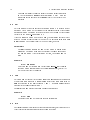
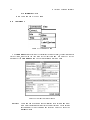
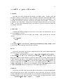
CA 1
1
6
4
CA 2
5
3
2
7
CA 3
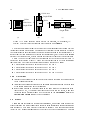
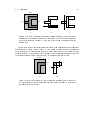
Figure 4.1: Overlapping Critical Areas
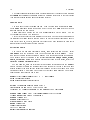
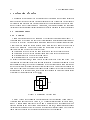
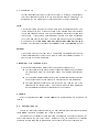
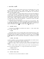
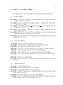
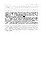
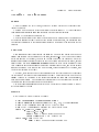
Figure 4.1 shows the overlapping of three fault primitive critical areas. Assume that CA
1 causes a fault aecting objects A and B, CA 2 causes a fault aecting objects B and C,
and CA 3 causes a fault aecting objects D and E. Specically how these faults would be
reported depends on the type of fault being extracted. However, Carafe places no arbitrary
limitations on the number of objects which may be involved in a single fault. The following
faults would be reported for the seven regions formed by the overlapping.
4.2. Bridges
15
A defect falling in region 1 aects objects A and B.
A defect falling in region 2 aects objects B and C.
A defect falling in region 3 aects objects D and E.
A defect falling in region 4 aects objects A, B, D, and E.
A defect falling in region 5 aects objects A, B, C, D, and E.
A defect falling in region 6 aects objects A, B, and C.
A defect falling in region 7 aects objects B, C, D, and E.
Physical defect sizes are specied as the radius of a circular defect. However, for
computational simplicity, these circular defects are approximated as squares where the
defect radius is one-half the length of a side.
4.1.2 Space/Time Considerations
Compound fault extraction as described above can be reduced to the rectangular intersection problem. However, the problem is complicated by the need to report the faults
by the objects listed in the overlapping fault primitives, and then to identify if the fault
aects the same objects as a previously found fault. If one is found, then these faults must
be merged. This must be repeated for each region formed by overlapping fault primitives.
This can be very costly in terms of both space and time requirements of the program, especially for moderately sized circuits and large defect sizes where there will be many small
overlapping regions involving many objects.
To help address these problems, two options have been added to Carafe. The rst option,
reduce fault primitives, instructs Carafe to perform preprocessing on the fault primitives
before they are sent to the compound fault extractor. The fault primitives are sorted by the
two objects in the circuit that they aect. For each pair of objects, all the fault primitives
which aect those two objects are sent through the compound fault extractor to remove any
overlapping. This has the eect of substantially reducing the input to the compound fault
extractor by removing redundant information for large defect sizes. However, for smaller
defects, this procedure will probably result in a decrease in performance, and thus should
only be used on relatively large defect sizes. Note that when compound faults are disabled,
this operation is performed on the fault primitives to remove some of the over-counting.
The second option, track critical areas, instructs Carafe to compute only the fault
probabilities and not to remember the critical areas. This has the eect of reducing memory
usage which may be necessary when extracting large circuits, but in no way aects the
relative probabilities of the faults. One side eect is that you will not be able to view the
faults in the graphical user interface.
4.2 Bridges
One of the most prevalent failure modes of spot defects is the shorting of electrical
nodes in the circuit. These failures are called bridges. Carafe classies bridge faults into two
categories: inter-layer and intra-layer. Inter-layer bridges occur when the layer of insulating
material between areas of conducting material is compromised and allows the conducting
areas to touch each other. Intra-layer bridge faults occur when extra conducting material is
present between two regions of a given type of material causing them to become electrically
connected together. Carafe makes no assumption about what layers can be bridged, and
16
4. Explanation of Faults
will only extract faults in or between layers listed in the bridge section of the technology
le.
Carafe identies bridge faults by the names of the nodes involved in the fault. Thus,
failures that bridge the same set of nodes together are considered the same fault even though
each failure may occur on dierent layers of material or in dierent areas of the circuit.
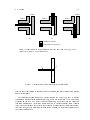
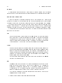
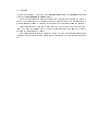
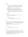
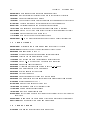
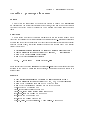
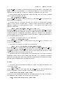
The bridge fault in Figure 4.2 is an example of an intra-layer bridge fault caused by
a spot defect falling between Node 1, Node 2, and Node 3. This bridge fault would be
reported as
(Node1 to Node2 to Node3)
indicating a 3-way bridge fault.
Node 3
Defect
Node 1
Node 2
Figure 4.2: A 3-way intra-layer bridge fault
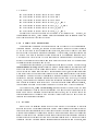
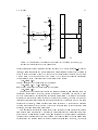
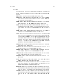
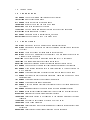
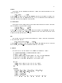
Consider the inter-layer bridge fault shown in Figure 4.3 (a). Since inter-layer bridges
are modeled as missing insulator, Node 1 and Node 2 would short together, Node 3 and
Node 4 would short together, but no other bridging would result from this particular defect.
Thus, this bridge fault would be reported as:
(Node1 to Node2) (Node3 to Node4)
indicating the two separate bridges in the same fault. If Node 1 and Node 4 were actually
the same node as in Figure 4.3 (b), this fault would be reported as:
(Node1 to Node2 to Node3)
which is the same fault as in Figure 4.2.
4.2.1 Critical Area Calculation
Carafe begins bridge fault extraction between two layers of material by nding all 2-way
bridge faults, or bridge fault primitives. Carafe nds intra-layer bridge fault primitives by
taking the material of a node and searching around it on all sides within a distance of the
maximum defect diameter. Any material in a dierent electrical node within this distance in
the same layer has a potential bridge. Carafe creates fault primitives that characterize the
critical area for the bridges. These characterizations are independent of the defect radius
and are called Length-Widths. This defect independent characterization allows the same set
of fault primitives to be used for the extraction of several dierent defect radii less than the
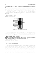
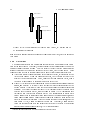
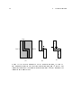
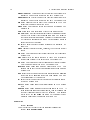
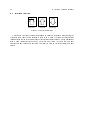
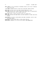
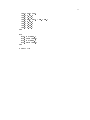
maximum. Figure 4.4 shows the three types of length-widths for intra-layer bridges which
4.2. Bridges
17
Node 3
Node 3
Defect
Defect
Node 4
Node 1
Node 1
Metal 1
Node 2
Metal 2
(a)
Node 2
(b)
Figure 4.3: (a) A 2 by 2 inter-layer bridge fault. (b) A 3-way inter-layer bridge
fault.
(a)
(b)
Conductive material
(c)
Length-Width Area
Figure 4.4: The three dierent length-widths for intra-layer bridge fault primitives, depending on the orientation of the conductive material: (a) diagonal, (b)
horizontal, (c) vertical.
depend on the orientation of the conductive material being bridged. Figure 4.5 shows the
critical areas for these length-widths.
For inter-layer bridges, Carafe looks for regions where the two layers overlap. The
length-width for an inter-layer bridge is simply the areas of overlap between the two layers
of material, and the critical area is the area of the length-width extended on all four sides
by the radius of the defect.
Once all bridge fault primitives between two layers have been found, Carafe computes
the critical area for each fault primitive given some defect radius less than or equal to the
maximum defect radius. Carafe then takes these defects and intersects them to nd the
faults, as described in section 4.1.1. After all compound faults for that defect radius have
been extracted, Carafe can recompute the fault primitive critical areas for another defect
radii and repeat the process. If a fault primitive does not cause a bridge at a defect smaller
than the maximum defect size, it is ignored for that smaller defect size.
18
4. Explanation of Faults
Critical Area
Length-Width
L
Defect
Critical Area
W
r
L
Defect
W
r
Length-Width
Defect
L
(a)
W
(b)
Critical Area
Length-Width
(c)
Figure 4.5: Critical areas for length-widths: (a) diagonal, (b) horizontal, (c)
vertical. Note that these critical areas were computed with fringe on.
The total critical area of a fault is the sum of all critical areas aecting the same objects
in each layer for each defect radius. The probability of that fault is then computed by scaling
the critical areas for each layer using the defect distributions given in the fabrication le. If
a bridge fault is given a probability of zero in the fabrication le, but is listed in the bridge
section of the technology le, bridges between those layers for that defect size are skipped.
Figure 4.6 shows the fault primitive critical areas for the circuit shown in Figure 4.2
given some defect radius. Figure 4.7 shows the four regions formed by these overlapping
fault primitives. The following bridging faults would be reported by Carafe:
A defect falling in region 1 would bridge Node 2 to Node 3.
A defect falling in region 2 would bridge Node 1 to Node 3.
A defect falling in region 3 would bridge Node 1 to Node 2.
A defect falling in region 4 would bridge Node 1 to Node 2 to Node 3.
4.2.2 Limitations
Inter-layer bridge faults occur only when there is a non-zero area of overlap between
the two conducting regions.
Intra-layer bridge faults are reported for ndiusion and pdiusion even when the area
of the failure is under the gate of a transistor.
Bridge faults between two dierent layers on the same plane will be considered intralayer bridges. So, if you want inter-layer bridges between two layers, make sure
the layers are on dierent planes. See the section on the Technology File in the
Customizing Carafe chapter for more on planes.
4.3 Breaks
Carafe also has the capability of extracting break faults, which result when a spot defect
occurs consisting of missing conducting material or extra insulating material; research has
shown breaks to be a common defect occurring in current CMOS fabrication processes
[Rog94] [RF94]. Breaks can cause a node to split into two or more smaller nodes. This can
4.3. Breaks
19
Node 1
Node 1
Node 3
Node 3
Node 3
Node 2
Node 2
Node 2
Node 1
(a)
(b)
(c)
Conductive material
Fault primitive critical area
Figure 4.6: Fault primitive critical area between: (a) Node 2 and Node 3, (b) Node
1 and Node 3, and (c) Node 1 and Node 2.
2
1
4
3
Figure 4.7: Intersection of three fault primitive critical areas.
result in nodes that cannot be charged to power or ground, and nodes that are only charged
under certain inputs.
The intra-layer breaks reported by Carafe indicate the eects of a spot of missing
conducting material or extra insulating material, with a size determined by the defect radii,
occurring on the chip. The result is broken connections, which leave formerly connected
terminals disconnected. Inter-layer breaks reported by Carafe represent failed contacts
(vias) but do not include spot defects that occur on a contact (nor do intra-layer breaks).
In other words, only the connection between layers is broken, while each layer connected by
the contact is unaected.
20
4. Explanation of Faults
In
Out
Vdd
Vdd
GND
GND
In
Out
Figure 4.8: The layout of a typical standard-cell inverter.
4.3.1 Critical Area Calculation
Carafe extracts break fault primitives one electrical node at a time by constructing a
graph for each electrical node using a plane sweep algorithm. The vertices in this graph
represent devices in the circuit, such as transistor terminals, transistor gate connections,
and I/O ports. Each vertex is given a unique name of the form node #, where node is the
name of the electrical node, and # a number which makes the name of each vertex unique.
The edges in this graph represent places where the electrical node can break; each edge has
a list of it length-widths which represent material that, if broken, cause the nodes to become
disconnected. Carafe creates fault primitives for each length-width on the edge lists, where
the names of the two objects aected by the fault will be the names of the two vertices in
the graph connected by the edge. Carafe repeats this process for each electrical node in the
circuit until all break fault primitives have been extracted. Carafe will then sort the break
primitives by layer and perform compound fault extraction one layer at a time.
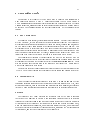
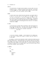
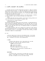
Figure 4.8 shows a simple inverter. Figure 4.9 (a) shows the graph constructed for the
In node and Figure 4.9 (b) shows the length-widths associated with each edge in the graph.
There are three kinds of length-widths: vertical, horizontal, and inter-layer. Length-widths
1, 2, 6, 7, 8 and 9 are vertical length-widths, 4 is a horizontal length-width, and 3 and 5
are inter-layer length-widths. The critical areas for the vertical, horizontal, and inter-layer
length-widths are the same as the horizontal, vertical, and diagonal length-widths shown in
Figure 4.5, respectively.
Carafe reports break faults by listing the pairs of nodes that are disconnected by the
breaks. For example, if length-width 1 from Figure 4.9 (b) were to cause a break, Carafe
would report the following break:
(In_0 and In_1)
Note that in Figure 4.9 (b) length-width 3 is a metal 2 contact break so it does not
interact with any other fault primitives during compound fault extraction. Carafe does not
4.3. Breaks
21
In_0
In_9
Edge 6
In_8
Edge 1
6
1
7
Edge 7
In_3
In_1
Edge 4
Edge 3
In_4
In_5
3
4
5
Edge 8
Edge 5
8
Edge 2
In_6
Edge 9
2
9
In_7
In_2
(a)
(b)
Figure 4.9: Conversion of the In node to a graph: (a) the graph of the node, (b)
the length-widths attached to the graph edges.
extract break primitives at junctions like that in Figure 4.9 (b) where vertex In 1 is located.
Instead, Carafe depends on the critical areas from breaks around the junction to overlap in
order to detect the break. Figure 4.10 shows the two critical areas for length-widths 1 and
2 from Figure 4.9 (a) for some defect size. Figure 4.10 (b) shows the resulting overlapping
critical areas. Region 1 represents the critical area for the break:
(In_0 and In_1)
region 2 represents the critical area for the breaks:
(In_0 and In_1) (In_1 and In_2)
and region 3 represents the critical area for the break:
(In_1 and In_2)
This procedure will produce inter-node compound break faults, and generally the most
\accurate" break faults. However, Carafe is capable of simplifying the process to save
both time and space by extracting only intra-node break faults. The change in the above
procedure is that after all fault primitives for a node are extract, they are be sorted by
layer and compound fault extraction is performed using only those primitives. Once fault
extraction is complete, Carafe discards these fault primitives. This process is repeated
for each electrical node in the circuit. After every electrical node in the circuit had been
extracted, all break faults have been found.
This procedural modication treats defects that break more than one node as though
only a single node was aected. This saves time and space since all break fault primitives
do not have to be available at the same time, and the number of possible faults is reduced as
there are fewer combinations of objects to break. The reduced input to the compound fault
extractor and the reduced fault size greatly improves performance. However, the critical
22
4. Explanation of Faults
Critical Area
Length-Width 1
Critical Area
1
2
Length-Width 2
3
(a)
(b)
Figure 4.10: (a) Critical areas for two length-widths 1 and 2, (b) Regions formed
by overlapping critical areas.
area for defects causing inter-node breaks are counted multiple times, once for each node
they break.
4.3.2 Limitations
The break extractor uses a two-pass plane-sweep algorithm which sacrices some accuracy for the sake of speed. As a result, there are several circuit congurations for which the
extractor cannot construct a graph. This is a result of the fact that the break extractor
actually constructs two graphs for each node in the circuit, one for each sweep. These
graphs are them merged in the nal graph that is used to create break fault primitives.
If there are multiple conducting paths in the fault-free circuit, this results in a cycle
in the sweep graphs. When the graphs are merged, the cycles are lost due to the
details of the merging algorithm. Thus, Carafe will not nd breaks in cycles, even if
the defect is large enough to break multiple edges in the cycle.
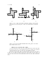
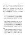
Figure 4.11 (a) shows a circuit conguration which the break extractor cannot properly
handle, and Figures 4.11 (b) and (c) show the length-widths extracted during the two
sweeps. Figures 4.12 (a) and (b) show the two possible graphs the break extractor can
generate1. Notice that the graph in Figure 4.12 (a) contains the edge for length-width
2 but no edge for length-width 5, and the graph in Figure 4.12 (b) contains an edge
for length-width 5 but no edge for length-width 2. The breaks caused by length-width
2 and 5 cannot both be represented in the same graph by the break extractor, and are
called conflicting breaks. Carafe resolves conicting breaks by throwing out the
one with the smaller critical area. If they both have the same critical area, as was the
case Figure 4.11 (a), Carafe will randomly delete one. As a result, Carafe may not
throw out the same break from one extraction of a circuit to the next. When Carafe
nds a conict during break extraction, it will issue a warning:
1
The electrical node name A and the vertex names were chosen arbitrarily.
4.3. Breaks
23
D
D
D
1
C
6
C
2
A
5
A
4
A
3
Sweep line
B
B
B
Sweep line
(b)
(a)
(c)
Figure 4.11: (a) A circuit which results in conicting breaks, (b) length-widths
found during the vertical sweep, and (c) length-widths found during the horizontal
sweep.
A_1
A_1
LW 1
LW 1
LW 4
A_0
LW2
LW 6
A_3
A_2
LW 6
A_2
A_5
A_5
LW 5
A_0
LW 4
A_3
LW 3
LW 3
A_4
(a)
A_4
(b)
Figure 4.12: (a) The merged graph containing length-width 2, and (b) the merged
graph containing length-width 5.
Warning: conflicting groupings in merge.
Note that since length-widths that do not cause breaks at the selected defect radii
are deleted before the two sweep graphs are merged, this problem only occurs for
relatively large defect sizes. See [Rog94] for more details about conicts.
There are a few cases where Carafe will introduce a small error in the critical area of
a break. This is because the plane-sweep algorithm it uses actually models a defect more
like a very thin line (the sweep line) breaking an LW across its width than a circular spot
defect.
C
24
4. Explanation of Faults
Notice in Figure 4.11 (b) and (c) that the regions where the sweep line is perpendicular
to the I/O ports have no length-widths associated with them. This is because a thin
sweep line perpendicular to the I/O port does not cause a break as the current can
ow around the break through the material connected to the port. A similar situation
occurs when polysilicon connects to the gate region of a transistor and around contacts.
When the diusion region of a transistor abuts the gate region, no breaks will be
extracted in either sweep in that region because the eects of a defect in that region
can be dicult to determine, especially for complicated transistors.
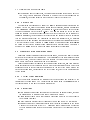
B
A
C
D
Figure 4.13: I/O port conguration that Carafe will not properly handle.
Figure 4.13 shows a situation where no breaks will be found. Although a relatively
small square defect could break A or C from the rest of the circuit, a thin line break
would not as the current could ow through the material connected to port B. Seldom
are ports arranged such that they are adjacent as in Figure 4.13, so this situation is
very rare.
Broken well contacts are not reported as no change in logical function results.
There are several additional limitations which appear when running in Hemlock mode
because the break extractor does not make subcell connections the same way the circuit
extractor does.
In order for the break extractor to make connections to subcells, there must be I/O
ports at the locations in the top level cell where material connects to a subcell port.
First, the stub of material connected to the subcell would be thrown out by the break
extractor, since Hemlock would not know that the material went anywhere. Secondly,
if the I/O port is not properly placed along the subcell port, then the break extractor
will silently ignore the port and not make the connection to the subcell.
A missing or misplaced label can cause big problems during simulation of break faults
if an input or output connection to a gate was not properly made. The following
warning messages appear when an I/O port is left o the connection to a subcell
feed-through:
PROBLEM: horizg has >1 con comp!
PROBLEM: vertg has >1 con comp!
indicating that a node which should have resulted in a single graph had several
connected components because the feed-through connection was not made.
4.4. Transistor Gate Bridge/Break Faults
25
When making subcell connections, the break extractor assumes subcells do not overlap. Thus, if a port connection is intended to be made to a cell that has another cell
overlapping, the break extractor may or may not identify the correct cell.
4.3.3 Output Files
The simulation le generated by Carafe (the .sim le) has an additional extension to the
lename. In this le, data for bridges and breaks are kept separate, and are distinguished
with .bridge and .break extensions, for example \my circuit.bridge.sim" would be output
for bridge extraction on the circuit my circuit. The primary reason for this is the node
renaming required to describe breaks; since all the pieces of a node must be renamed to
guarantee uniqueness, the node names in the layout are not present without modication
(see the previous subsections). By separating the faults into separate les, we maintain
compatibility with any programs that previously used the output les for analyzing bridges.
Note that Carafe will only generate a .break.sim le if compound breaks are disabled
as Carafe will not resolve identical break transistors from dierent faults. Appendix G
describes the .graph le which details compound break faults for simulation.
4.4 Transistor Gate Bridge/Break Faults
Carafe now supports transistor gate bridge/break faults, which are the result of missing
polysilicon in the gate region of a transistor. As a consequence of the self-aligning processes
in wide use today, this defect results in both a break in the gate region of the transistor
and a bridge between the diusion regions of the transistor.
Carafe extracts breaks in transistor gates during break extraction, and then performs
extra processing on the gate breaks in order to nd the corresponding bridges. Thus these
breaks have edges in the electrical node subgraph with the rest of the circuit breaks. For
each bridge/break fault, Carafe reports two sets of node lists, one for the bridges and one
for the breaks.
4.4.1 Critical Area Calculation
The critical area calculations for transistor gate bridge/breaks are identical to the
calculations for break faults. The critical areas are scaled using the breaks section of
the fabrication le to compute the relative probabilities.
4.4.2 Limitations
Since transistor gate breaks are extracted the same way as normal breaks, the same
limitations apply to transistor gate bridge/breaks as to breaks.
Carafe assumes that a defect that causes a gate break primitive will bridge exactly
two diusion terminals.
Bridge/breaks in dierent types of transistors (pMOS and nMOS) do not interact.
Transistor gate bridge/breaks are reported even if nothing is separated by the break.
Consider the circuit shown in Fig 4.8. Transistor bridge/breaks would be reported
for both transitors even though the polysilicon on one side of the transistor is just a
stub.
26
4. Explanation of Faults
The overlapping of critical area from transistor gate breaks and adjacent polysilicon
breaks are not considered by the break extractor.
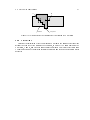
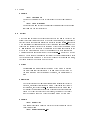
4.5 Gate Oxide Short Faults
n-poly gate
n-poly gate
Gate Oxide
n + diff
Source
n+ diff
Drain
p+ diff
p+ diff
Drain
Source
n-well
p-substrate
Figure 4.14: Gate Oxide Short
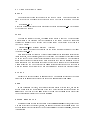
Another fault type that Carafe is capable of extracting is Gate Oxide Short (GOS) faults.
Figure 4.14 shows a cross section of a circuit showing the possible GOS faults that Carafe
will nd. These faults are modeled like Bridges by adding extra transistors in the netlist
for testing and simulations. Carafe reports these faults as shorts between the diusion and
polysilicon regions of the transistor. The weight of the GOS for each transistor type is listed
in the gos section of the fabrication le.
GOS fault extraction can be enabled by pressing the button label "Gate Oxide" in the
Bridges section of the Extract window. GOS faults are output the same way that bridge
faults are, i.e. they appear in the .pro le.
4.5.1 Critical Area Calculation
Carafe calculates the relative likeliness of a GOS fault by taking the area of a transistor's
active region and dividing it up by the number of diusion regions, i.e. source and drain.
Figure 4.15 shows how the critical area for a GOS fault is calculated. Both faults 1 and 2
are calculated by taking the area of the transistor (AB) and dividing it by the number of
diusion regions (2). To weigh the relative occurrence of GOS faults, use the polysilicon to
ndiusion or polysilicon to pdiusion defect densities in the fabrication le.
GOS faults
B
1
A
Polysilicon
2
Diffusion
Figure 4.15: Calculation of Critical Area for GOS faults
4.5. Gate Oxide Short Faults
27
A
B
Diffusion
Polysilicon
Figure 4.16: Limitations for the calculation of critical area for GOS faults
4.5.2 Limitations
Currently the calculation of the critical area for GOS faults in Carafe does not take into
account the geometry of the transistor. For example, in Figure 4.16 Carafe would nd two
GOS faults, A and B, and give both faults equal critical area. This is not correct since fault
A should have a higher critical area because the diusion and the polysilicon share a longer
perimeter.
28
5. Circuit Extraction
5. Circuit Extraction
This chapter describes the important details of Carafe's circuit extractor.
5.1 Electrical Nodes
Carafe ensures that each node will have a unique name to dierentiate it from other
nodes. Carafe determines the names of electrical nodes by arbitrarily choosing one of the
labels attached to material composing that node. If a node has no labels attached, then it
is given a name of the form carafe n, where n is a number which makes the name unique.
If the node's name is already used, it will simply have \ 0" added after it; the number will
be increased for other instances of the same name so that each is unique. This ensures
that nodes that are not physically connected in the layout do not become connected in the
netlist that is output by Carafe (transistor level for normal mode, gate level for Hemlock
mode).
The labels given to nodes and I/O ports must be placed correctly for Carafe to identify
them and treat them correctly. Each I/O port must be labeled on the edge of the material
that would be connected to other parts of the circuit. If a label is placed on a corner, the
results are unpredictable, since Carafe doesn't know which edge is being labeled. If Carafe
is unable to attach a label to any routable material, then it will give a warning similar to
the following:
ExtLabelNodes: could not attach label a_s2 to a tile at (42,53) (ignoring).
In hierarchical circuits, all of the labels will have the names of the circuit instances
prepended to it in the form of circuit1/circuit2/label. As a result, node labels that are
not at the highest level of hierarchy will be changed and this must be reected in the test
patterns that may exist for the circuit. One way to get around this problem is to place the
labels used in the test pattern at the highest level of hierarchy.
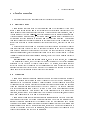
5.2 Transistors
Carafe is now capable of handling transistors which more than two diusion terminals.
Carafe will create a netlist based on what it considers to be the two-way transistors, or
transistors with two diusion terminals. Carafe denes a two-way transistor as a region
of transistor gate in which a vertical or horizontal line can be drawn though the gate and
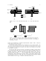
touch one diusion terminal on each side of the gate. Figure 5.1 (a) shows a transistor
with three diusion terminals. Figure 5.1 (b) and (c) show the two-way transistors Carafe
creates for this transistor. Gate regions 1 and 2 form transistors with Di1 and Di3 as
terminals, regions 4 and 5 form transistors with Di2 and Di3 as terminals, and regions 3
and 6 form transistors with Di1 and Di2 as terminals.
Carafe computes and reports information about transistors based on the two-way transistors and merges those with the same diusion terminals. The width of a transistor is the
amount of diusion perpendicular to the channel of the two-way transistor gate. Carafe
computes the minimum channel width and the average channel width as the minimum and
average distance between two diusion terminals, respectively. The area of a transistor is
the sum of the areas of the two-way transistors, and the position of the transistor is the
center of the bounding box the two-way transistors.
5.2. Transistors
29
Diff 1
3
6
Gate
Diff 2
1
2
5
4
Diff 3
(a)
(b)
(c)
Figure 5.1: (a) shows a transistor with three diusion terminals, (b) shows two-way
transistors with horizontal diusion terminals, and (c) shows two-way transistors
with vertical diusion terminals. Notice how some regions of transistor gate are
counted twice.
This simple method of extracting transistors leads to some inaccuracies in the transistor
area as shown in Figure 5.2 and Figure 5.3. Also, Carafe will allow the gate of a transistor
to be connected to a diusion terminal but will only allow a node to be attached to one
diusion terminal. Thus, Carafe will not distinguish between separate diusion regions with
the same node and will only list the node in the transistor terminal list once.
Diff 1
Gate
1
2
Diff 2
(a)
(b)
Figure 5.2: (a) shows a transistor with two diusion terminals, and (b) shows the
two-way transistors with horizontal and vertical diusion terminals. The corner is
the transistor gate is ignored.
30
5. Circuit Extraction
Gate
2
Diff 2
Diff 1
1
3
4
(a)
(b)
(c)
Figure 5.3: (a) shows a transistor with two diusion terminals, (b) shows 2way transistors extracted with vertical diusion terminals, and (c) shows 2-way
transistors extracted with horizontal diusion terminals. Region 1 represents the
transistor gate counted twice.
31
6. Customizing Carafe
The purpose of this chapter is to give a new user of Carafe a brief explanation of
what Carafe does and how it does it. Carafe was designed to work with a variety of
CMOS manufacturing processes and is fully customizable in its fault extraction. To control
Carafe's extraction, parameters such as defect radius size and likelihood weighting need to
be specied. These parameters and the les that contain them will be explained in this
chapter.
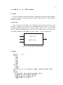
6.1 How Carafe works
For Carafe to work properly, several input les are required. The rst is the technology
le (the .tech le), this le describes the circuit's fabrication technology. The technology
le contains descriptions about the number of layers of material, contacts and vias, and so
on. The next le that Carafe requires is the fabrication statistics le (the .fab le). This
le contains the list of defect radii that will be used to extract the realistic faults from the
layouts and the scaling factors that are used to approximate defect distributions by both
defect size and by fabrication layer. Of course, Carafe needs the layouts of the circuit. The
layouts can be in either the Calma GDSII format or the Berkeley Magic format.
The graphical user interface of Carafe requires two les to work properly. One le
contains a description of all the styles that layers of material can be drawn in and the other
le contains the color map for the drawing styles (the dstyle and colormap les). These
les are the same ones that are used in the Berkeley Magic layout tool. Please refer to
Magic documentation for more details.
The Hemlock version of Carafe requires a le that describes the cells that are used (the
.lib le). The le must contain the coordinates of all the inputs and outputs of each cell.
6.2 Technology File
This le denes the fabrication technology being used. The number and names of the
conducting layers are dened as well as the contacts or vias that connect them. Also, interactions between layers, such as polysilicon and diusion forming a transistor, are specied
in this le. Each dierent fabrication process may require its own Carafe technology le.
Purpose
The technology le (.tech) describes the technology that will be used to fabricate
the circuits to be analyzed by Carafe. Each fabrication technology has its own Carafe
technology le since layer names and types may change from process to process. Examples
of information in the technology le include which layers can be used as routing wires,
which combinations form transistors, which layers are connected by vias, which layers may
be shorted together in the presence of fabrication defects, a mapping of GDS layer numbers
to layer names, and the colors that layers will be displayed in.
32
6. Customizing Carafe
Technology File Sections
The technology le is composed of several sections each of which begin with a keyword
describing the name of the section followed by any number of data lines for the section and
nally the keyword end. All section names and the keyword end must be in lower case in
order for Carafe to recognize them.
Each line of the technology le can be a maximum of 80 characters in length. Characters
in excess of 80 are ignored and case is important. Comments can be inserted in the
technology le as long as they do not appear within sections. Comment lines begin with
the # character and any text following it is ignored by Carafe. At least one space must be
between the # character and the body of the comment line.
The following is a description of each section type recognized by Carafe. These are
similar to the sections used in the Berkeley Magic technology les. Carafe checks that each
tech le has at least a tech, planes, and types section dened. No ordering of the sections
is required except for what is specied in the section descriptions below.
tech
The tech section is used to describe the name of the technology being dened
in this le, which may be dierent from the actual name of this technology le.
The name of the technology being used by Carafe is reported on the console
when Carafe is rst run.
If Magic les are being loaded into Carafe, the technology name in the Magic
le must match the name of the technology Carafe is using. Otherwise, Carafe
will not load the circuit.
planes
Carafe stores a circuit's layout information in a set of planes. Each of these
planes is used to hold polygons of one or more types of material or layers. In
general, layers that interact with each other to create new \types" of layers (e.g.
polysilicon and ndiusion interact to create a transistor \type") must reside on
the same plane. All other layers are stored on their own plane (e.g. metal1).
This section denes the names of the planes to be used to represent circuit
layouts. Each line in this section contains a single entry used for the name of
a plane; plane names can contain no white space characters. In the current
version of Carafe, a maximum of 7 planes can be specied. An additional plane
is used to represent subcircuits and need not be specied in the technology le.
types
The types section denes the names of the layers that will reside on each plane.
Each line of this section contains a pair of names. The rst name in the pair is
the name of the plane to use. Each plane name must be dened in the planes
section and thus this section must follow the planes section. The second name
in the pair is the name of the layer to be placed on the plane. The second name
can be a comma separated list of names all of which will be treated as the same
layer. Contacts are not included in the section but are dened in the contact
section.
6.2. Technology File
contact
All contacts and vias between layers are specied in the contact section. Each
line in this section denes the connectivity of one type of contact. The line begins
with the name of the contact layer followed by two lists of comma separated layer
names. Each list contains the layer types on a given \side" of the contact. Make
sure that each list does not contain any white space as the white space is used
to delimit the end of one list and the beginning of the other. The layer names
must have been specied previously in the types section.
connect
Since it is possible to have more that one layer on a plane, it is necessary
to indicate which layers on the plane are considered electrically connected if
they are physically adjacent on the layout. The connect section is the place
where this information is provided. Each line in this section contains two comma
separated lists of layers. Each layer in one list is considered electrically connected
to each layer in the other list if they are physically touching in the layout. Make
sure that no white space is in each comma separated list as a white space is used
to determine the end of one list and the beginning of the other.
compose
This section denes how composite layers are generated. Since Carafe represents
transistors as a separate layer, regions where polysilicon and diusion overlap
must be converted to the transistor layers. This is done in the compose section.
Each line in this section denes a layer that is made up of possibly several other
layers that overlap each other. The new layer exists only where all of the specied
layers overlap each other. Each line consists of three elds. The rst contains
the name of the plane that the particular composition will take place on. The
plane name must have been dened previously in the planes section. The next
eld is the name of the composite layer being dened. This layer name must be
one that is dened in the types section. The last eld is a comma separated
list of the layers that combine to make the new layer type. Each layer must be
on the plane specied and must have been dened in the types section.
Note: If one composite type is a subset of another, the smaller composite
type must be specied before the larger. For example, suppose we have two
composite types to dene, ndiusion and ntransistor. The ndiusion layer is
composed of active area and n-implant, and the ntransistor layer is composed of
active area, ndiusion and polysilicon. We can see that the set of layers to create
the ndiusion is a subset of the layers for ntransistor. Problems may result if
all areas of overlapping active area and n-implant are converted to ndiusion
before composing the more specic ntransistor. Since Carafe processes the list
of composites from the last to the rst, the ntransistor record must appear
below the ndiusion record. Another way to do this would be to add a record
before the ndiusion record that would specify the ntransistor being composed
of ndiusion and polysilicon.
33
34
6. Customizing Carafe
calma
In the Calma GDS le format, the dierent layers are given numbers rather
than names. This section provides a mapping of the GDS numbers to the
corresponding layer names. Each line in this section lists the name of a layer,
which must have been dened in the types section, followed by the GDS layer
number to which it corresponds.
extract
In order to perform the circuit extraction process, Carafe needs to know which
layers represent the transistors in the circuit. Each line in the extract section
denes the information required to identify a single type of transistor. A line
begins with the word fet and is followed by the string that will be placed in the
.sim le to identify the type of the transistor. The layer that represents the
transistor is given next and it must be a layer that has been dened in the types
section above. Next is the name of the electrical node to which the substrate of
the transistor is connected. The last item in the line is the name of the layer that
is used as the diusion terminals (source and drain) for the transistor. Again,
this layer must be dened in the types section.
route
Carafe must be told which layers carry signals and which do not. The route
section provides this information. Each plane dened in the planes section
should have a line in this section listing the layers that carry signals on that
plane. A line begins with the name of a plane followed by a comma separated
list of layers that carry signals on that plane.
bridge
Carafe does not make any assumption on which layers may be involved in a
bridge fault. Therefore, the pairs of layers that can be bridged together must be
listed in this section. Each line in this section denes one kind of bridge that can
occur. A line contains the names of the two layers that can be bridged together
and, of course, they must be dened in the types section. For intra-layer bridge
faults, the same layer name is given for both layers.
fault
This section is used to dene the transistor types that Carafe will use to represent
the extracted faults. There are three lines in this section. One denes the
transistor to be used for bridge faults, one for break faults and one for gate
oxide faults. The lines begin with either the word break, bridge, or gos to
indicate which fault type is being dened. Following this word is the name of the
transistor to be used to represent the fault transistor in the .sim le. Next are
two integers dening the size of that fault transistor. The rst integer denes
the length of the transistor channel and the second denes the width of the
channel in centimicrons. Finally, the logic value (0 or 1) is listed that activates
6.3. Fabrication File
35
the fault and causes the fault to occur in the circuit. Originally, it was intended
that these transistors be used in switch-level fault simulation. Currently, most
users parse the .sim output les to create Spice les for circuit simulation.
color
This section is used to dene the colors of each layer for display purposes. This
is only required for the X Windows version of the program and is not needed
for the non-graphical version. This section contains a single line for each layer
color desired. A line begins with a layer name followed by a comma separated
list of style numbers for that layer. The style numbers are given in the dstyle
le described in the Command Line Options and Environment Variable
sections. The layer must be dened in the types section or the contact section.
autoat
This section lists the cells that are to be attened out automatically once a
circuit containing one of these cells is read in. Each line contains the name of
one cell that is to be auto-attened.
Technology File Creation Hints
This section contains some useful hints for creating a technology le.
The layers that are combined to make transistors (usually polysilicon and
the diusions) must all be on the same plane. This includes layers such as
wells.
Try to create a separate plane for each type of signal carrying layer (except
when the layer must be combined with other layers to make transistors).
The fault transistors should be much larger in width than the size of the
transistors in the normal circuit. This tends to make the fault simulation
more meaningful when drive strengths need to be resolved.
Example
Refer to the included le mcnc.tech in carafe/lib for an example of a technology le
format.
6.3 Fabrication File
To help the user create fabrication les, we have supplied a user interactive program
called Fabit. Appendix D explains how to use this program.
The likelihood of occurrence of each fault can be dependent on the layer on which the
defect falls and on the size of the defect. Because of this, the likelihood of occurrence
computed for each fault can be scaled based on the tables in the defect statistics le.
36
6. Customizing Carafe
Purpose
The fabrication defect statistics le (.fab) is used to provide Carafe a list of the scaling
factors to use in the computations of the relative probability of occurrence for each fault.
Fabrication File Sections
This le is made up of dierent sections similar to the technology le. Each section
begins with the name of the section on one line followed by any number of lines dening
the data of the section. The section is then completed with a line containing the word end.
Comments may be placed in the le as long as they fall between sections and do not
appear within a section. A comment line is a line that begins with the # character and
continues to the end of the line. Any text that follows the # character is ignored by Carafe.
A description of all the sections is given below. Note that the section description words
must all be in lower case.
fab
The very rst section of the le must be the fab section. This section is made
up of three lines. The rst line contains the word fab. The second line contains
the name used to label the set of statistics given in the .fab le. This name
can be dierent then the actual le name. This name is reported when Carafe
is rst started up. The last line of this section contains the word end.
types
The next section denes the dierent layers that the statistics are dened for.
The rst line contains the word types. Each line after the rst contains a single
name of a layer that has been dened in the technology le's types section. In
this le, however, only the layers that conduct signals in the circuit are typically
specied. This section is completed with a line containing the word end. This
means that no layer may be called end.
The fab section must include at least every layer that is dened in the routes
section of the technology le.
gos
The gos section lists the weights to be used in calculating the weighted critical
areas for the gate oxide shorts. Each type of transistor (e.g. ntransistor,
ptransistor) is assigned a certain weight. The default weighting for all types
of transistors is 0.0. To change this, place a line in this section containing the
name of a transistor type followed by the weight to assign to this type.
Note that the transistor type being assigned here must also be listed in the
types section of the fab le also.
The next three sections must always appear as a group.
6.3. Fabrication File
37
radius
The rst section of the group species the radius of the defect used for the set
of numbers to follow. The radius section is made up of three lines. The rst line
is the word radius. The second contains an integer dening the defect radius
in centimicrons. The last line contains the single word end.
break
The next section lists the scaling factors for break faults in the various layers of
material. This section begins with a line containing the word break. Following
this must be the same number of lines as in the types section of numbers that
are to be used to scale the probabilities on the dierent layers. The numbers
listed are in the same order as the layers are dened in the types section above.
These numbers are usually less than one, but are not limited to it. The last line
contains the word end.
bridge
The last section of the group is a nn matrix used to scale the probabilities of
bridge faults between all layers. This section begins with a line containing the
word bridge. Next follows the n n matrix where n corresponds to the number
of types listed in the types section. The format is as follows:
type1 type2 : : :
type1
type2
:::
The last line contains the word end. The matrix dened here is redundant, but
a check is made to insure that the data in the array is symmetric about the
main diagonal.
The grouping of the last three sections can be repeated as many times as needed, once for
each defect radius desired. When Carafe reads this le, it automatically sets the minimum
and maximum defect sizes to the smallest and largest radii listed in this le, respectively.
These minimum and maximum defect sizes are used by the fault extractor to determine
which faults to include in the list of probable faults. Only those defects between the these
minimum and maximum radii are considered.
Example
fab
scmos
end
types
ntransistor
metal1
metal2
38
6. Customizing Carafe
end
gos
ntransistor 0.5
end
radius
400
end
break
0.03
0.10
0.34
end
bridge
0.01 0.30 0.0
0.30 0.23 0.05
0.0 0.05 0.23
end
radius
500
end
break
0.01
0.05
0.13
end
bridge
0.01 0.25 0.0
0.25 0.15 0.01
0.0 0.01 0.15
end
6.4 Library Description File Format
A gate library description le (.lib) consists of records that describe the input and
output order and coordinates of all the gates in the cell library. This le is required for
the Hemlock version of Carafe only. Each record is a single line of text of no more than
80 characters in length. Every record begins with a keyword followed by a string of data
for that record. The keywords must be in all upper case letters. An example of this le is
provided at the end of this section.
LIBRARY
The record that indicates the name of the library being dened is the LIBRARY record.
The format of the record is:
LIBRARY lib name
where LIBRARY is the keyword for the record and lib name is the name of the library. The
lib name must be a single word, i.e. it may contain only letters and digits.
6.4. Library Description File Format
39
BLOCK
The description for each gate begins with the BLOCK record. This record denes the
name of the gate to be dened in the records to follow. The format of the BLOCK record
is:
BLOCK gate name
where the word BLOCK is the keyword describing the record type and gate name is the name
of the gate to be dened.
INPUT
To dene the inputs to the gate, the INPUT record is used. Each INPUT record denes
a single input to the gate and lists the coordinates of the input. Thus a two-input gate
requires two separate INPUT records|one for each input. The following is the format of
the INPUT record:
INPUT input name location1 location2 ... locationN
The word INPUT is the keyword describing the the record type and the name of the input
is given by input name.
Each input location is given by a 3-tuple of data containing the fabrication layer that the
input resides on, the x coordinate, and the y coordinate. The coordinate of the input should
be on the edge of the cell where the interconnect wires will be connected. The coordinates
are in units of integers of centimicrons. Each element in the 3-tuple is separated by white
space characters. The fabrication layer must be one that is dened in the corresponding
Carafe technology le. The order that the INPUT records are specied here is the order in
which the inputs will be placed in the .TDL le generated by the Hemlock version of Carafe.
OUTPUT
Outputs of a gate are dened in OUTPUT records. The OUTPUT records have the exact
same format as INPUT records except the keyword is OUTPUT rather than INPUT.
FEED
In some standard cell gates, feed through lines are placed within a gate, but are not
used in determining the logical function of the gate. These lines are specied by using the
FEED record. The format of the FEED record is the same as the INPUT record except that
the keyword INPUT is replaced by the keyword FEED.
POWER and GROUND
Power and ground for each gate is dened by the POWER and GROUND records, respectively.
The format for these two records is, again, the same as the format for the INPUT record. The
keyword INPUT is merely replaced by the keyword POWER or the keyword GROUND, whichever
is appropriate.
40
6. Customizing Carafe
END
The nal record for each gate is the END record. This record marks the end of the
denition of the gate and its format is:
END gate name
where the word END is the keyword dening the type of the record and the gate name is the
name of the gate just dened. The gate name should be the same as the gate name stated
in the BLOCK record dened previously.
Comment lines can be inserted anywhere in the library le. Comment lines begin with
the "#" symbol. See the example below for a single cell in the MCNC.LIB le.
Example
# Library file for the mcnc standard cell library
LIBRARY mcnc
BLOCK a2s
INPUT a
INPUT b
OUTPUT q
FEED
u1
POWER Vdd
GROUND GND
END a2s
metal2
metal2
metal2
metal2
metal1
metal1
100
900
2500
1700
3100
3100
5700
-100
-100
-100
5100
-100
metal2
metal2
metal2
metal2
metal1
metal1
100
900
2500
1700
-100
-100
-100
5700
5700
5700
5100
-100
41
7. Running Carafe
Depending on which version of Carafe was compiled for your machine, you will either
have a command-line interface or an X Window interface. Both versions of Carafe are
invoked the same way, using command-line ags to set parameters. The sections below
apply for both interfaces of Carafe.
In order to extract the list of realistic faults, the layout of the circuit must be analyzed.
The layout can be provided to Carafe in either the Calma GDS format or the Berkeley
Magic le format. Only rectilinear circuits can be analyzed by Carafe; circuits with nonrectilinear geometries are approximated by a series of rectangles if read using the Calma le
format. Carafe will accept hierarchical designs, but they will be attened to a single level
of hierarchy before the fault extraction takes place. A description of the Magic le format
that Carafe can read is given in Appendix I.
The graphical version of Carafe requires two additional les, a .dstyle le and a .cmap
le. These two les describe how the layers of material are to be drawn on the screen. See
the Environment Variables section of the Installing Carafe chapter for information on
setting the variables CARAFE DSTYLE and CARAFE COLORMAP.
7.1 Invoking Carafe
To run Carafe, type carafe at the operating system prompt ( % for some systems) and
press <return> as shown below.
% carafe
Options can be used to tailor the Carafe session; these options are specied by typing
the particular option ag followed by the parameter for that option. The option ag and
the parameter must be separated from each other by at least one space. See the Carafe
Option Flags section below for information on option ags. An example of this is given
below.
% carafe -t scmos.tech
The above command will execute Carafe using the le scmos.tech in the current directory
for the technology le rather than the default technology le.
The names of the technology le and the defect statistics le are reported at the
beginning of the session. Check to make sure that they are correct before reading in circuit
layouts.
If the X Window version of Carafe was compiled, the command-line version can still be
used by giving a false display name. To do this, type something like the following:
% carafe -display lkj
where lkj is a nonexistent display.
7.2 Carafe Option Flags
The following is a list of all valid option ags for Carafe:
42
7. Running Carafe
-a number This controls the \fringe area" calculation for critical areas. A non-
zero number turns the addition of the fringe area on. A zero number will
turn the addition of fringe areas o. The default number is 1 for on.
-c le name This option indicates that the le given is to be used to read
commands from. The full pathname must be specied. If the last command
in the le is not quit, commands will be read from the keyboard after
executing the last command in the le.
-C path This option allows the user to specify the cell search path.
-d level This option sets the debugging level to level. This option is used for
generating debugging output and should normally not be used.
-D le name This option sends all debugging messages to the named le. The
le is truncated when it is opened.
-e le name This option appends all error messages to the named le.
-f le name This option species the fabrication defect statistics le to be used
to rank the fault probabilities. The default le is carafe.fab. The full
pathname must be specied.
-g le name This option species the le that describes the graphics drawing
styles used for drawing the layout geometries. Look in the Environment
Variables section for more details on .dstyle les.
-h This option simply prints out the valid option ags for the program and
returns to the operating system without invoking Carafe.
-l Used only in the Hemlock version, this ag species the le to be used for
the standard cell library denitions.
-m le name This option species the le that contains the colormap data for
drawing the layout geometries. For further information on the .cmap les,
look in the Environment Variables section.
-o le name This option indicates that all messages normally sent to the screen
are to be appended to the specied le.
-p char This option causes the prex character char to be removed from all
labels.
-s number When reading in GDS format les, non-Manhattan geometries are
approximated using a series of smaller rectangles. The default step size is 1
centimicron and may generate a very large number of rectangles. This will
degrade the performance of Carafe's fault extractor. This option allows the
step size to be set to any size in centimicrons to minimize the number of
approximating rectangles.
-t le name This option species that the given le should be used as the
technology le instead of the default carafe.tech. The full pathname
must be specied.
7.3 Outputs
The transistor level netlist of the original circuit and any faults that were found, represented as transistors, are output in the form of a .sim le. This le can be used directly
with most of the CAD tools from various universities. The format of the .sim le generated
7.3. Outputs
43
is given in Appendix K. Also refer to the Output Files section of the Breaks description
given in the Explanation of Faults chapter.
The list of faults and their relative probabilities of occurrence are listed in the .pro le.
Each of the probabilities of occurrence reported is broken down by the dierent layers of
material causing the fault. More detail of the format of this le can be found in Appendix J.
Carafe generates a le that can be used directly with the COSMOS switch-level simulator. The .src le contains a list of COSMOS fault simulator commands to be used to
simulate the faults found by Carafe.
Both Carafe and Hemlock also output a .loc le. This le gives information about the
location of the wires in each fault. Please refer to Appendix H for more information on this
le.
44
8. Carafe Command Line Interface
8. Carafe Command Line Interface
This chapter describes the Carafe commands and their syntax. In Carafe, all commands
and parameters are case sensitive. All Carafe commands must be entered in lower case
letters or they will not be interpreted correctly by the Carafe interpreter. Parameters such
as le names are also case sensitive. For example, the two le names, inv.mag and Inv.mag
are treated as two dierent les by Carafe.
Carafe is an interactive tool that can be controlled by command line entries. Commands
are given to Carafe by typing in the desired command at the Carafe prompt:
carafe>
A typical Carafe session entails the reading in of the design for a circuit, performing the
circuit/fault extraction and then simulating the resulting circuit.
The general format of a Carafe command is:
command option parameter
where command is any of the commands described in this chapter. The option and parameter
specify the exact sub-command and parameters to use for the command. Each of the three
parts of the command can be separated by any number of tabs or spaces. Only one command
is allowed per line and each line is limited to 80 characters in length. Any characters in
excess of 80 are ignored.
The default circuit name is used in the commands which require only a circuit name as
a parameter and none was given. The current default circuit name is shown in the Carafe
prompt following the colon (:). If a circuit name is specied for any command, the default
circuit name is changed to the specied name.
8.1 ca
The ca command is used to display the critical areas for faults. The command
will list all the rectangular regions composing the critical areas for the specied
fault. The regions will be sorted by defect radius and layer.
Options
The ca command requires the type of fault as an option. There are
four types, one for each type of fault extracted by Carafe:
bridge species a bridge fault
break species a break fault
gos species a gate oxide short
bb species a transistor gate bridge/break fault
help prints out a brief description of the ca command options and parameters
Parameters
Two parameters can be given; the rst is required and the second is
optional. The rst parameter is the number of the fault to print and
the second is the name of the cell to look in for the fault.
8.2. extract
Example
carafe> ca bridge 42
The above command lists the critical areas for bridge fault number
42.
carafe> ca bb 2 inverter
The above command lists the critical areas for transistor gate bridge/break
fault number 2 in the inverter cell.
8.2 extract
This command initiates the extraction process on the named circuit or the
default if no circuit name was given. If the circuit is hierarchical, it is attened to
one level before the extraction unless told otherwise through the no at option.
A le containing the transistor netlist of the circuit and any faults found will be
created in the current directory with the name of the cell as the le name with
a .sim extension. The likelihood of occurrence of the faults are reported in the
le with the .pro extension. Refer to the appendices for more information.
All unlabeled nodes are given a label of the form carafe # where the # is some
number. These labels will appear on the layout (if graphics are available) after
the circuit has been extracted. If the circuit is saved via the write command,
the labels created will be saved with the circuit.
Options
The extract command requires the name of the circuit to perform
the circuit and fault extraction on. The name must be one listed by
the command list. If no circuit name is specied, the default name is
used.
Parameters
The circuit extractor will automatically atten a hierarchical circuit to
one level, if necessary creating a new circuit. If attening the circuit is
not desirable, specifying the no at parameter after the circuit name
will prevent the attening process from occurring before the extraction
starts. Note that in order to use this feature, the name of the circuit
must be specied explicitly. Using the default circuit will not work.
Example
carafe> extract inv
This example instructs Carafe to begin the circuit extraction on the
circuit named inv.
carafe> extract adder no at
45
46
8. Carafe Command Line Interface
This example instructs Carafe to execute the circuit extraction process
on the circuit named adder without attening it rst. Only the
conducting layers specied in the adder level of the circuit will be
processed.
8.3 at
This command will take the specied circuit and reduce it to a single level of
hierarchy. A new circuit will be created for the attened version of the original
hierarchical circuit. The name of the new circuit will be the name of the original
circuit with the string \ f" appended to it.
If there is already a circuit with the new name, the attening process will not
proceed. The newly created circuit will be lost if it is not saved using the write
mag command. The original circuit will still be intact, however.
Parameters
The at command requires the name of the circuit to atten as the
parameter. The name given must be one that is dened as shown by
the list command. If no circuit name is given, the default name is
used.
Example
carafe> at adder
This command will create a new circuit called adder f that contains
the same circuit information as the original adder circuit, but all of
it will be at one level of hierarchy.
8.4 help
This command will show all of the valid Carafe commands and a brief description
of what each command does. Optional parameters for the commands listed by
help are enclosed in the angle brackets < and >. Required parameters are
enclosed in the square brackets [ and ].
The help command does not have any options or parameters.
Example
carafe> help
The above command will print out the help information.
8.5 info
The info command is mainly used for debugging purposes, but can be used to
collect statistical information about the program as it runs.
8.6. list
47
Options
alias Prints out a list of node names and the list of other names that
were on the same node but were not used as the nal name of
the node. This command only works after the circuit has been
extracted.
help Prints out a brief summary of the info commands.
labels Prints out the list of labels dened for the given circuit.
labeldevices Prints out the list of label devices found during break
extraction. This command is not available in Hemlock mode.
tiles Print out a list of the bounding box of the circuit in centimicrons
and a count of the tiles used to represent the circuit by type of
tile.
Parameters
For most of the info commands, only a single circuit name need be
specied (or the default circuit name).
Example
carafe> info labels inv
This will print out the list of labels dened in the inv circuit.
8.6 list
This command will show all the names of currently dened circuits as Carafe
knows them by. These names must be used where circuit names are required
for other Carafe commands. Note that these may be dierent from the names
of the les for the circuit.
The list command does not have any options or parameters.
Example
carafe> list
A list of currently dened circuits will be shown.
8.7 quit
To end the current Carafe session, execute the quit command. Note that any
new circuits created (as a result of hierarchy attening) and not written will
be lost. No messages are printed out to warn the user of potential circuit loss.
Circuits that were not created by Carafe are not aected by this and need not
be written in order to save them.
The quit command does not have any options or parameters.
48
8. Carafe Command Line Interface
Example
carafe> quit
The above command will terminate the current Carafe session.
8.8 read
This command is used to read in the denition of a circuit. After a circuit is read
in, the name of the circuit appears in the list produced by the list command.
The extract command can now be performed on the circuit.
Options
The options for the read command indicate the le format of the
circuit denition to be read. The following are the currently supported
le formats:
gds Calma or GDS-II le format
mag Magic le format
help prints out a brief description of the read options
Parameters
The parameters for the read command is a single le name. The
le name must be a complete pathname to the le containing the
denition of the circuit.
The le extensions need not be specied as they are assumed by
Carafe. For the mag le format, the le extension is assumed to
be .mag and the le extension .strm is assumed for the Calma le
format. If the le extension is dierent from the assumed ones, they
can be specied by appending it to the le name.
Examples
carafe> read mag inv
The above command instructs Carafe to read in the le inv.mag using
the Magic le format.
carafe> read gds inv.stm
This command instructs Carafe to read in the le inv.stm using
the the Calma le format. Note that this example does not use the
assumed le extension of the GDS format.
8.9 set
This command is used to set the variables used in Carafe. The list of variables
that can be changed by the set command are in the Options section.
8.9. set
49
Options
The following is a list of all of the variables that can be set during the
current Carafe session and the types of values that the variables can
be set to.
show Shows the state of all the parameters listed below.
break onjo Turns break fault extraction on or o. Setting break
on will allow the detection of breaks to occur. Setting break o
will disable all break variables.
breakI onjo Turns inter-layer break detection on or o. This variable is also set by the set break command. Default is on.
breakN onjo Turns inter-node break extraction on or o. If compound faults have been disabled, then this variable has no eect.
This variable is also set by the set break command. Default is
on.
breakP onjo Turns planar break detection on or o. This variable
is also set by the set break command. Default is on.
bridge onjo Turns bridge fault extraction on or o. Setting bridge
on will set both overlap and side to side bridge fault extraction
to on. Setting bridge o will set both overlap and side to side
bridge fault extraction to o. The set bridge command is used
only as a short cut to turn both types of bridge fault extraction
on or o. The state of the bridgeI and the bridgeP variables
determine which bridge faults will be extracted.
bridger onjo Controls whether the bridge types le is output in
Hemlock mode. Default is on.
bridgeI onjo Turns overlap bridge fault extraction on or o. This
variable is also set by the set bridge command.
bridgeP onjo Turns side to side bridge fault extraction on or o.
This variable is also set by the set bridge command.
ccshort onjo Controls whether the cell adjacency le is written.
This works in Hemlock mode only. Default is o.
compound onjo Turns compound fault extraction on or o. Default is on.
circuit name Sets the default circuit name. The circuit name must
already exist as given by the list command.
cosmos onjo This controls whether the .src le is output for use
with the COSMOS switch level simulator. This variable is o by
default in Carafe and is disabled in Hemlock.
maxdefect integer Set the maximum defect radius used for the extraction process in centimicrons. integer must be a defect radius
from the .fab le. The default is the largest radius in the .fab le.
mindefect integer Set the minimum defect radius used for the extraction process in centimicrons. integer must be a defect radius
from the .fab le. The default is the smallest radius in the .fab
le.
50
8. Carafe Command Line Interface
gateBridge on o Controls whether the gate level bridge fault list is
j
generated. This works in Hemlock mode only. Default is on.
gateBreak onjo Controls whether the gate level break fault list is
generated. This works in Hemlock mode only. The default is on.
gos onjo Turns Gate Oxide Short (GOS) extraction on or o. GOS
extraction is disabled in Hemlock mode.
graph onjo This controls whether the graph le is generated. The
default is on.
help Prints out a brief description of the set command options.
lambda integer Sets the conversion factor used to create and read the
Magic le for a circuit (see the write command). The default is
100 centimicrons per lambda unit. Changes to the lambda setting
will only aect subsequent le reads. Circuits already loaded in
are not aected by this value.
loc onjo Controls whether the fault locations le is generated. Default is o.
prex character Causes the prex, character, to be removed from all
labels.
pro onjo This controls whether the fault likelihood le is generated.
Default is on.
prob value Limits the faults reported to those with a likelihood
greater than or equal to the value given. The default is 0.0.
sim onjo This controls whether the transistor level netlist is output.
This is disabled in Hemlock mode. The default is on.
reduceFP onjo Turns fault primitive reduction on or o. This
variable has no eect when compound faults have been disabled.
Default is on.
step integer Sets the stepsize to be used in converting non-Manhattan
geometries into Manhattan geometries when reading GDS les.
The default value is 1 centimicron.
tdl onjo Controls whether the gate level netlist is generated in Hemlock mode. Default is on.
trackCA onjo Turns fault critical area tracking on or o. Default
is on.
transBB onjo Turns transistor bridge/break faults on or o. If
intra-layer break faults have been disabled, then this variable has
no eect; transistor faults will not be extracted. This variable
is also set by the set break command. This variable is on by
default in Carafe and is disabled in Hemlock mode.
Examples
carafe> set show
This will print out the state of all the changeable parameters.
carafe> set maxdefect 2000
8.10. shell
Sets the size of the maximum defect radius to 2000 centimicrons,
assuming defect statistics have been provided for this defect in the
fabrication le.
8.10 shell
This command allows operating system commands to be executed from within
the Carafe session. This can be used to list all the les in a directory, print a
le, or any other operating system command.
Options
The option for the shell command is the actual command that is to
be executed by the operating system along with any parameters it
may need. If no option is given, Carafe will suspend its execution and
run a copy of the operating system shell. To return to Carafe from a
shell, type exit at the operating system prompt.
Examples
carafe> shell
Execute a sub shell. Return to Carafe by typing exit.
carafe> shell lpr a le
This will execute the lpr program (printing on UNIX systems) and
give it a file as a parameter.
8.11 source
This command instructs Carafe to read subsequent commands from the specied
le. If the last command in the le is not quit, Carafe will resume reading
commands from the console or the previous source le. The source command
may be nested, so that one source'd le may execute the source command on
another le. When the second le is exhausted of commands, Carafe will resume
reading and executing commands from the rst le just after the rst source
command. There are two ne points here to look out for: make sure that les do
not source each other in a circular fashion and that any quit commands found
while source'ing a le will terminate the current Carafe session immediately.
Options
The source command does not have any options.
Parameters
The source command requires a single le name as a parameter. The
complete path must be provided.
51
52
8. Carafe Command Line Interface
Example
carafe> source inv.command
Carafe will begin reading commands from the le inv.command as a
result of the above command. If the last command in the le is not
the quit command, Carafe will resume reading commands from the
console.
8.12 time
The time command reports the amount of UNIX system time and user time
in seconds that the last command required to execute. The time required to
execute the time command cannot be reported.
The time command has no options or parameters.
Example
carafe> read mag inv
carafe> time
Executing the time command above will report the amount
of time taken to read in the inv.mag le.
Executing the time command immediately again will report
the same time.
8.13 write
This command is used to write out the layout description of a circuit to a le.
When using the mag option, the parameter lambda (see the set command) is
used to scale the dimensions of polygons placed in the output le. The lambda
value indicates the number of centimicrons per lambda unit written in the .mag
le. The value of lambda is placed in the .mag le as a comment for future
reference.
Options
The options for the write command indicates the format of the le
to write. Valid formats are given below.
mag Use the Magic le format.
help Prints out a brief description of the write command.
Parameters
The parameters for the write command is the name of the circuit to
write as dened by the list command. Only circuits shown by the list
command can be written out. If no circuit name is given, the default
circuit will be written out.
8.13. write
The name of the le to write to can also be specied by entering the
name of the le following the name of the circuit to write. Thus, to
write to a le name other than the default, the name of the circuit
must be given.
The extension of the le created will be .mag for the Magic le format,
unless an extension is given by specifying the le to write to.
Example
carafe> write mag inv
This will create a le called \inv.mag" and place the denition of the
circuit inv into it using the Magic le format.
carafe> write mag inv new inv.mag
The circuit called inv will be written out to the le \new inv.mag" in
the Magic format.
53
54
9. Carafe X Window Interface
9. Carafe X Window Interface
The Motif-based graphical user interface oers a pleasant and easy to use environment
for Carafe. Commands and options are set using pop-up menus instead of typing in the
command at the Carafe prompt. The Command Line Interface chapter contains more
detailed information of what the commands do; this chapter just explains what commands
are available. With the use of buttons and option windows, settings for Carafe are displayed
and changed in an easy-to-use and understand manner. The sections below describe the
options under the main menu bar titles File, Commands, and View. Figure 9.1 shows
the main Carafe screen; this is what the user rst sees upon loading Carafe.
Figure 9.1: Main Carafe screen
9.1 File Menu
Figure 9.2: File Menu
The File menu oers le related options to the user. See Figure 9.2 for the layout of the
various menu items for File. These menu selections have the following properties/eects:
Open... This option pops up a window oering settings for le lters, changing
directories, and opening les. Figure 9.3 shows the open le window.
Save... This option pops up a window for saving the current le. The directory
and le name are changeable so moving and renaming les is possible.
The Save window looks very similar to the Open window.
9.1. File Menu
55
Figure 9.3: Open File Window
Figure 9.4: Preferences Windows
Preferences... This option displays a window with the various settings used by Carafe.
The settings are Debug Level, Fringe, Lambda, Prex Character, Minimum Probability, Step Size, and Cell Path. These settings are explained in the Carafe Command Line Interface chapter in the Set
section and also in the Running Carafe chapter. Figure 9.4 shows
56
9. Carafe X Window Interface
the Preferences window.
Exit This menu item will exit Carafe.
9.2 Commands
Figure 9.5: Commands Menu
The Commands menu oers items for extracting the loaded circuit, getting information
on the circuit, and getting the time used for the last command. See Figure 9.5 for the
hierarchy of the Commands menu. The options available are listed below.
Figure 9.6: Extract Options Window
Extract... This menu item pops up a window displaying the minimum and maxi-
mum defect radius and buttons for the extract options. These options
are equivalent to their command-line versions. Figure 9.6 shows the
Extract window.
9.3. View
57
Info This menu item allows the user to display circuit information such
as: Aliases, Labels, Label Devices, and Tiles. These options will
display their information in the command window from which Carafe
was started. For more information of these commands refer to the
Command Line Interface chapter.
Time This menu item gets the time used by the last command and displays
it in the command line window.
9.3 View
Figure 9.7: View Menu
The View menu oers the user options for viewing various circuits, faults, layers, and
labels. Controls are given so the user may quickly and easily select or remove items to be
displayed. See Figure 9.7 for the options available for this menu. These options are listed
below.
Figure 9.8: Circuits Window
Circuits... This option lists the currently loaded circuits and allows the user to
select which one to display. Figure 9.8 shows the window for the
Circuits menu item.
58
9. Carafe X Window Interface
Figure 9.9: Faults Window
Figure 9.10: CA Panel
Faults After the faults have been extracted from a circuit this command can
be used to display the faults extracted. A window pops up listing
the faults along with their likelihood. The user may select faults and
zoom in to their location in the layout for closer inspection. The user
may also view the critical areas by defect radius and layer. Figure 9.9
shows the window for the Faults menu item. Pressing on the CA
Panel button when a fault is selected will bring up another window
shown in Figure 9.10. This window shows the individual rectangles
that form the critical area for a fault. (I use it often.)
9.3. View
59
Figure 9.11: Layers Window
Layers... This option pops up a window displaying the layers of the current
circuit. The user can select which layers are to be displayed by pushing
the button associated with each layer. The color for each layer is also
displayed next to the selection button for reference. This window does
not disappear when changes are applied, but remains visible for turning
layers on and o quickly. The window for the Layers menu item is
shown in Figure 9.11.
Figure 9.12: Labels Window
Labels This option is used to turn on or o the display of the labels for
the circuit. The user simply enters the name of the label or regular
expression (i.e. C shell) in the box provided and selects either Add
or Remove to add or remove the label or expression. The user then
selects Done and the eect is reected in the display. Figure 9.12
shows the window for the Labels menu item.
60
9. Carafe X Window Interface
9.4 Interface Controls
Full View
Zoom In
Zoom Out
Figure 9.13: Zooming Buttons
There are two methods for zooming available in Carafe. One method uses buttons, the
other uses the mouse to select the area to zoom in on. Figure 9.13 shows the three buttons
that appear in the lower left hand corner of the Carafe graphics window. These buttons are
used to zoom in and out on the circuit. The other way to zoom is to hold the left mouse
button down and \window" a portion of the circuit to zoom in on; then release the mouse
button.
61
10. Hemlock
Hemlock is a special version of Carafe that is used to analyze standard cell based designs.
Hemlock does not atten the circuit since it is only interested in nding faults at the top
level. The benets of not attening are that extractions are faster, larger circuits can be
analyzed, and a gate level description of the fault list can be generated.
Hemlock looks and acts exactly like Carafe. The only visual dierences being the lack
of a atten option in the Extract window and the inclusion of more le output options
like .ccshort, .bridger, .gateBreaks, .gateBridge, and .tdl. The major underlying
dierence between Carafe and the Hemlock version is that Hemlock is aware of the structure
of the logic cells. Thus, Hemlock knows that nodes can run through logic gates and come
out the other side of the gate. This information comes from the .lib le.
The Hemlock version of Carafe extracts faults only from a circuit's top level of hierarchy.
Thus, to analyze the interconnection wires for faults, the layout needs to be organized such
that the top level of hierarchy only contains the interconnect wires and that all of the cells
are at the next lower level of hierarchy. This allows the Hemlock version of Carafe to see that
a wire runs through a cell and out to another wiring channel; Carafe, which uses a attened
netlist, cannot do this. Hemlock does not output a .sim le as it assumes there are no
transistors in the top level cell. Faults are identied in the .gateBreaks and .gateBridge
les.
Hemlock and Carafe together can be used to extract almost all the realistic faults in a
large circuit more quickly than Carafe alone by using Carafe to nd all the faults in each cell
and Hemlock to nd those in the routing channel. This saves computation time, memory,
and disk resources by extracting the faults from each cell once instead of for every instance
of the cell. Also the gate-level description generated by Hemlock facilitates fault simulation
and test pattern generation of the extracted faults. For an example of how this is done, see
[FL91].
10.1 Installing
Installing Hemlock consists of make a softlink to the Carafe executable name hemlock.
The command-line to do this would look like this:
ln -s /path_name/carafe hemlock
10.2 Running Hemlock
Hemlock is invoked by entering hemlock at the command prompt. Carafe looks at how
it was executed to determine what version to run, i.e. Carafe or Hemlock.
Running Hemlock would look like this:
% hemlock
10.3 Inputs
As mentioned in the How To Use Carafe chapter, Hemlock requires another input
le besides the ones used by Carafe. Hemlock requires a .lib le which gives information
62
10. Hemlock
on cell libraries. This le may be loaded with the option ag, -l, when executing Hemlock
or it can be set in the environment as explained in the Environment Variables section
of the Installation chapter.
10.4 Outputs
Hemlock outputs some additional les besides the ones that Carafe outputs. The
new les have extensions of .bridger, .ccshort, .gateBreaks, .gateBridge, and .tdl.
Please refer to Appendix B, Appendix C, Appendix E, Appendix F, and Appendix M
for information on these le formats. These les are used by test pattern generators like
Nemesis for Automatic Test Pattern Generation (ATPG) [Lar90] [TL92].
63
Appendix A. Revision History
This chapter lists all of the major changes of Carafe from one version to the next.
A.1 Alpha-Alpha.1
28Nov1990 Comments in the technology le were not handled right. Comments can now
be inserted between tech sections.
29Nov1990 Labels on contacts were not handled correctly. The label is now moved to one
of the layers of the contact.
01Dec1990 Cell instances start with \ 0" rather than \ 1" to be consistent with the
Berkeley Magic CAD tool.
03Dec1990 Time command modied for UNIX systems to report user and system time
rather than wall-clock time.
04Dec1990 Hemlock version to output TDL incorporated into Carafe. Hemlock is an
experimental version of Carafe and is not supported!
05Dec1990 Fixed the problem of erroneous material being added under a contact when
reading from a GDS le.
A.2 Alpha.1-Alpha.2
12Dec1990 Changed to a faster cross-planar bridge algorithm.
12Dec1990 Fixed errors in critical area calculation for cross-planar bridges.
22Jan1991 Close window option added to the * commands.
04Feb1991 Added code to check for transistors with less than two diusion terminals.
18Feb1991 Check for moving a label out of the circuit's bounding box.
18Feb1991 Forgot to mark the rst tile found in the transistor region algorithm.
27Feb1991 The set bridge and break commands check for the keywords on and o explicitly.
28Feb1991 Support for MSDOS dropped.
05Mar1991 Critical areas are not computed using defect data larger than the maximum
defect size.
A.3 Alpha.2-Alpha.3
14Mar1991 Motif user interface added.
24Mar1991 Star commands changed to info commands.
24Mar1991 Main Makele changed to be more intuitive.
22Apr1991 Reading the fabrication le reports undened layers right away rather than
when writing the .pro le.
30Apr1991 GDS parser beefed up to catch errors while reading.
21Jun1991 The \-s" option was added to allow changing the step size used in converting
non-Manhattan geometries to Manhattan in GDS les.
64
Appendix A. Revision History
28Jun1991 Bridge fault nodes are reported in alphabetical order.
09Jul1991 Bug in determining the largest defect size in the fab stat le corrected.
12Jul1991 Labels on contacts are now ignored.
15Jul1991 Added switches to allow selective extraction of overlap and side by side bridges.
01Aug1991 Adding a contact now correctly updates the cell's bounding box.
05Dec1991 Cell instance numbers in Magic les are now preserved.
15Apr1992 GDS parser now stops on rst error rather than trying to continue.
06May1992 Fixed Motif GUI bug when trying to extract without attening the circuit.
11May1992 Fixed derivation of kitty-corner LW's.
11May1992 Zero width or height LW's are removed now.
29Jun1992 NO TIME C preprocessor ag added for systems without either function.
A.4 Alpha.3-Alpha.3.1
29Jun1992 Cell instances can be given a name using the property 112 record.
29Jun1992 Saved memory by not copying layer names to label objects.
06Jul1992 Save panel added to the GUI.
13Jul1992 Log and error les are now appended rather than created.
13Jul1992 Using time in command line used to quit.
14Jul1992 Mag le read bug xed. Initializations weren't being done.
14Jul1992 Fixed NO TIME compile bug. #dene in the wrong place.
22Jul1992 Label prex char removal added.
22Jul1992 All function prototypes can be used or not via NO PROTO.
23Jul1992 GDS Parser reads in PATH elements now.
28Jul1992 Hemlock updated for this version.
28Jul1992 Auto at cells added.
28Jul1992 Labels on space used to choke the Magic le reader.
29Jul1992 GDS parser skips cells that have already been dened rather than stopping.
31Jul1992 Settings panel added to GUI.
07Aug1992 Step size comment added to mag les.
13Aug1992 Stdin ushed when a INT interrupt occurs.
17Aug1992 Extract progress messages added.
18Aug1992 Bug in GDS array reading xed.
04Sep1992 Only the faults with non-zero likelihoods are output in the .sim le and the
.pro le now.
25Sep1992 The numbers in the bridge matrix of the fab le are checked for consistency.
23Oct1992 Fault modules split into bridge and break version.
A.5 Alpha.3.1-Alpha.3.2
21Jul1993 Tech and fab le are recorded in sim and pro les.
A.6. Alpha.3.2-Alpha.4
65
A.6 Alpha.3.2-Alpha.4
16Nov1992 Added the minimum fault probability level control.
10Mar1993 Sub cell search path added.
21Apr1993 Automatic le format detection added.
16Jun1993 Hemlock code is now compiled with Carafe.
08Feb1994 Gate oxide shorts added to Carafe.
14Feb1994 The GDS parser can read les that use cells before they are dened.
01Mar1994 Break faults added to Carafe.
05Apr1994 Labels are moved to routable layers, if possible.
03May1994 Added LW panel to the GUI in debug mode.
A.7 Alpha.4-Alpha.5
12Oct1994 Fixed a bug in the GDS parser which read reals incorrectly.
20Oct1994 Fixed a bug where no sim le would be generated if no fault type was selected
to extract.
08Dec1994 Added more cong le information in the output les.
09Dec1994 Moved the X defaults into the executable. This eliminates the need for the
Carafe le in the lib directory.
05Jul1995 Added label devices to map break netlist names to I/O port names.
18Jul1995 Compound intra-layer bridge faults implemented.
26Jul1995 Faults now track and display critical areas instead of length-widths.
01Aug1995 Added option to compute only fault probabilities and not critical areas.
02Aug1995 Fixed regular expression calls in Label functions to compile correctly on
HPUX machines.
03Aug1995 Compound faults can be extracted over a selected range of defect radii.
11Aug1995 The fault view dialog has been redesigned. Faults can be viewed by defect
radius and layer.
16Aug1995 Compound inter-layer bridge faults implemented.
18Aug1995 Compound break faults implemented.
23Aug1995 Magic le reader moves labels on contacts to one of the layers connected by
the contact.
28Aug1995 Enhanced response to XExpose events to reduce redundant drawing.
31Aug1995 Break extractor handles transistors with more than two terminals correctly.
04Sep1995 Transistor gate bridge/break faults implemented.
13Sep1995 Carafe allows nodes to be connected to the gate and diusion of the same
transistor.
14Sep1995 The circuit is not redrawn if the zoom box is too small.
19Sep1995 Added .graph output le.
25Sep1995 Carafe performs a more detailed analysis of transistor regions during circuit
extraction.
28Sep1995 Carafe does not extract faults in layers with zero probability.
66
Appendix A. Revision History
05Oct1995 Hemlock will determine the inputs and outputs to the top level cell and put
them in the .tdl le.
11Oct1995 Uses autoconf script to check system settings and generate Makeles.
08Nov1995 Fixed bug in magic le reader that caused arrays not to work.
12Dec1995 Fixed bug in GDS reader that sometimes caused reals to be read incorrectly
on architectures with a word size greater than 32 bits.
20Dec1995 Carafe will allocate a private colormap if the default is full.
30Dec1995 Fixed bug that caused labels to sometimes appear in the wrong place when
zooming.
02Jan1996 Fixed bug in the break extractor that caused overlapping I/O ports to sometimes cause problems.
04Jan1996 Added application resource to specify layout label font.
08Jan1996 Workaround for Motif bug in some versions of XmStringGetLtoR.
67
Appendix B. .bridger File Format
Purpose
This le lists the cell list types for bridge faults found by the Hemlock version of Carafe
in the .gateBridge le. This le is output for ATPG programs for testing inter-cell bridge
faults.
Description
The le begins with lines of comments beginning with a # symbol and a space. The
general format of the .bridger le is as follows:
# cellname.bridger generated by Carafe of Hemlock Version Alpha.5
# Tech file: techfilename techfiledate
# Fab file : fabfilename fabfiledate
...
type_N cell1 ... cellN
...
where type N is the Nth cell list type and cellN is the cell driving some node. Each type is
taken from the cell list of a bridge fault in the .gateBridge le. If a cell list appears more
than once in the .gateBridge le, then it appears only once in the .bridger le.
Example
Here is the .bridger le for the example shown in Appendix F.
# test.bridger generated by Carafe of Hemlock Version Alpha.5
# Tech file: /tst/mcnc.tech Thu Oct 13 17:32:31 1994
# Fab file : /tst/scmos2.0.fab Fri Oct 14 15:55:00 1994
type_0 i1s aoi21s
type_1 input ai2s
type_2 input i1s input
type_3 ai2s ai2s ai2s
type_4 ai2s ai2s
type_5 cia cic input cib
68
Appendix C.
.ccshort
File Format
Appendix C. .ccshort File Format
Purpose
The .ccshort le is produced by Hemlock for use by the CCShort fault simulation
program. The le gives information on the pairs of adjacent cells which exist in the layout;
the cell name, orientation, and instance name are given for each cell in the pair.
Description
The le begins with lines of comments beginning with a # symbol and a space. The
format of the .ccshort le is as follows:
# cellname.ccshort generated by Carafe of Hemlock Version Alpha.5
# Tech file: techfilename techfiledate
# Fab file : fabfilename fabfiledate
...
cell1_orient1_cell2_orient2 cell1_instance cell2_instance
...
where cell1 and cell2 are the cell names, orient1 and orient2 are each either 's' for
sideways or 'n' for normal or no transform. The last two entries are the instance names for
the cell1 and cell2, respectively. cell1 is always the one on the left, cell2 is on the
right, ordering is important.
Example
# test.ccshort created by Carafe of Hemlock Version Alpha.5
# Tech file: /tst/mcnc.tech Thu Oct 13 17:32:31 1994
# Fab file : /tst/mcnc.fab Fri Oct 14 15:54:02 1994
fts_n_ai2s_n fts_0 ai2s_0
ai2s_n_ai2s_n ai2s_0 ai2s_1
69
Appendix D. FABIT
Purpose
Fabit is an application that creates a Carafe fabrication le (.fab) when supplied with
fabrication process information. While it is possible to create a .fab le from scratch, it is
dicult to take into account all the variables that can aect the fabrication le. Fabit was
written to make it easier and faster to create a reliable .fab le.
Usage
Fabit is invoked from the UNIX prompt by simply typing fabit. Once you have run
Fabit, it will ask you a series of questions. In order to create a correct .fab le, it is
necessary to have the following available:
1. A Carafe technology le that Fabit uses to determine routeable process layers, contact
names, transistor types, and which layers can be bridged together.
2. Name of the fabrication process, e.g. scmos.
3. Whether Fabit should ignore defects that are to small to cause a fault on a given layer.
4. Whether Fabit should ignore defects that are large enough to potentially cause compound faults.
5. Minimum feature width on each layer of material in centimicrons.
6. Minimum feature spacing on each layer of material in centimicrons.
7. Gate Oxide Short (GOS) scaling factors.
8. Relative probabilities of bridge or break fault occurring.
9. The defect distributions by size for each layer and fault type.
10. Number of defect radii to use in the distribution.
11. The size of each defect radius in centimicrons.
Fabit requires a Carafe technology le to operate. It uses the tech, types, contact,
and route sections of the specied technology le to determine the process layers to list in
the .fab le. It uses the bridge section to determine which pairs of layers may be bridged
together and the extract section to determine transistor layers.
The name of the fabrication process can be used as a description so that the user knows
which .fab le is being used when running Carafe. It is suggested that .fab les with
dierent specications should have dierent names.
Fabit can do two dierent kinds of defect size checking. It can ignore defects that are
to small to cause a fault, and/or defects that could potentially cause compound faults. A
defect is considered to small to cause a bridge if r < s2i where r is the defect radius and
s is the minimum spacing for layer i. A defect is considered to small to cause a break if
wi
r <
2 where r is the defect radius and w is the minimum width of layer i. A defect is
considered capable of causing compound bridge faults if r > 2w2i +si where r is the defect
radius, w is the minimum width for layer i, and s is the minimum spacing for layer i. A
defect is considered capable of causing a compound break fault is r > 2si2+wi where each
variable is the same as before. If either minimum or maximum defect size checking are
needed, then Fabit must be told the minimum width and spacing rules for each layer. If
neither are needed, then Fabit will not prompt for the rules.
70
Appendix D. FABIT
Next, Fabit will prompt for the GOS scaling factors. Fabit uses the layers specied in
the extract section of the technology le to determine transistor types. The scaling factors
must be between 0 and 1 (inclusive).
Next, Fabit will prompt for the relative probabilities and defect distributions for each
pair of bridgeable layers listed in the bridge section of the technology le. If fty percent of
the bridges that occur are bridges from metal1 to metal1, then enter .5 when asked Enter
probability (metal1 to metal1). Fabit will then prompt for a defect distribution for
that bridge type. Once all relative probabilities have been entered, Fabit will normalize the
probabilities to 1.0. If there is more than one radius, Fabit will distribute the normalized
1 .
value across all the radii using the equation: p = rdist
Next, Fabit will prompt for the relative probabilities and defect distributions for break
faults. Each routeable layer and contact type is considered breakable by Fabit, and each
has its own probability and defect distribution. Once all probabilities have been entered,
Fabit will normalize the probabilities to 1.0. Again, if there is more than one radius, Fabit
1 .
will distribute the normalized value across all the radii using the equation: p = rdist
If an improper value is entered at one of the prompts, Fabit will generate an error
message. This usually means that the last value entered was not an acceptable value, fabit
will tell you why the value was not acceptable and prompt for the information again. Once
all the questions have been answered, Fabit will respond with \Fab le written to disk."
Data les created by Fabit can be piped back into Fabit to create a new .fab le. Data
les may contain comment lines beginning with a \#" character to make modifying them
easier. Note that the normalized probabilities will appear in the data le, and may dier
from those entered.
71
Appendix E. .gateBreaks File Format
Purpose
The .gateBreaks le can be output when breaks are extracted in Hemlock mode. This
le describes the eects of the breaks at the gate level of the circuit.
Description
The le begins with lines of comments beginning with a # symbol and a space. The
format of the .gateBreaks le is as follows:
# cellname.gateBreaks generated by Carafe of Hemlock Version Alpha.5
# faults extracted with defect radii of: radius, ... centimicrons.
# Tech file: techfilename techfiledate
# Fab file : fabfilename fabfiledate
...
break name (terminal list) (terminal list)
..
.
...
(terminal list)
..
.
(terminal list)
where break name is the name of the break, such as \brk 1", which will also identify the
break in the .pro le. Each entry contains one line for each node involved in the break.
Each line contains n + 1 terminal lists for the n breaks in that node. Each terminal list
is a comma separated list of terminals, where a terminal is either an I/O port or a cell
input or output. I/O ports are identied by name, cell inputs and outputs are specied as
instance name/port name, where instance name is the name of the instantiation of the
cell, and port name is the name of that cell's port to which the node in question is attached.
Example
# test.gateBreaks created by Carafe of Hemlock Version Alpha.5
# faults extracted with defect radii of: 325, 265, 175 centimicrons.
# Tech file: /tst/mcnc.tech Thu Oct 13 17:32:31 1994
# Fab file : /tst/scmos1.2.fab Fri Oct 14 15:54:35 1994
brk_0 (aoi21s_0/a1) (ai2s_3/q, ai2s_1/b)
brk_1 (ai2s_3/b) (I6gat)
brk_2 (I22gat) (ai2s_2/q)
(I1gat) (ai2s_0/a)
brk_3 (ai2s_0/b) (ai2s_3/a, I3gat)
() (aoi21s_0/a1) (ai2s_3/q) (ai2s_1/b)
brk_4 (I23gat) (i1s_1/q)
(I22gat) (ai2s_2/q)
(I1gat) (ai2s_0/a)
brk_5 (ai2s_2/b) (i1s_0/a) (ai2s_1/q)
(aoi21s_0/a1, ai2s_3/q) (ai2s_1/b)
72
Appendix F.
.gateBridge
File Format
Appendix F. .gateBridge File Format
Purpose
This le lists the faults found by the Hemlock version of Carafe. The .gateBridge
le contains only the possible interconnect bridge faults, since Hemlock does not atten
the cells of the circuit. This le is output for ATPG programs for testing inter-cell bridge
faults.
Description
The le begins with lines of comments beginning with a # symbol and a space. Each
line of the le contains the cell names separated by an underscore ` ', nodenames separated
by space and the weighted critical area. For inter{layer bridge faults that may have several
shorts in the same fault, semicolons separate the node lists for each short. The general
format is as follows:
# cellname.gateBridge generated by Carafe of Hemlock Version Alpha.5
# faults extracted with defect radii of: radius1, ... centimicrons.
# Tech file: techfilename techfiledate
# Fab file: fabfilename fabfiledate
...
cell1_..._cellN node1 ... nodeN critical_area
...
where cellN is the cell driving nodeN and the critical area is the critical area of the fault
as found in the .pro le. cellN can also be input, which means the node is driven by a
primary input.
Example
# test.gateBridge generated by Carafe of Hemlock Version Alpha.5
# faults extracted with defect radii of: 325, 265, 175 centimicrons.
# Tech file: /tst/mcnc.tech Thu Oct 13 17:32:31 1994
# Fab file: /tst/scmos2.0.fab Fri Oct 14 15:55:00 1994
i1s_aoi21s I13 I7 1440000.000
input_ai2s I1gat I22gat 3000000.000
input_i1s_input I1gat I23gat I2gat 1640000.000
ai2s_ai2s_ai2s I12 I22gat I8 770000.000
ai2s_ai2s I10 I12 3260000.000
ai2s_ai2s I12 I22gat 1360000.000
cia_cic_input_cib IA53 carafe_2 ; IB42 carafe_5 360000.000
73
Appendix G. .graph File Format
Purpose
The graph le gives a hierarchical description of a faulted circuit. However, the main
purpose of this le is to provide an ecient mechanism for reporting compound break faults.
A graph representation of a circuit is given with edges provided for possible breaks. A list
of breaks is then given, specifying which edges are broken by each break. The eect of
a break on the circuit can be determined by removing the aected edges from the circuit
graph. All other types of faults are listed in this le as well, but more detailed listings can
be found in other les.
Description
Comment lines can appear anywhere in the le. These lines will always have a # symbol
at the beginning of the line.
The information in this le is divided into sections. Each section has the following
format:
section_name
entry...
...
end
where section name is either netlist, brknodes, bridgebreaks, bridges, breaks, or gos.
The following is a description of each of these sections.
netlist
This section describes all the two-way transistors in the circuit. Each transistor appears
on a line with the following format:
trans_# type gate diff1 diff2 x y min_length avg_length width area
where trans # is the name of the transistor, such as trans 42, type is the transistor type,
gate, diff1 and diff2 are the names of the nodes connected to the gate, diusion terminal
1, and diusion terminal 2 of the transistor, respectively, x and y are an approximate
location of the transistor, min length is the minimum channel length, avg length is the
average channel length weighed by the width of the channel, width is the width of the
channel, and area is the total area of the transistor. See the Transistors section in the
Circuit Extraction chapter for exactly how these values are computed.
brknodes
This section is present only when breaks have been extracted. It denes a subgraph for
each electrical node in the circuit. There are two types of entries in the section. The rst
denes a subgraph for each electrical node in the circuit and the second describes how this
subgraph connects to the rest of the circuit. The rst entry type has the following format:
node node_name edge1 ; edge2 ; ... ; edgeN
74
Appendix G.
.graph
File Format
where node name is the name of the electrical node whose subgraph is being dened, and
edgeN is an edge in the subgraph. The edges are described by the two vertices in the
subgraph that are connected by that edge. Each edge is separated by a semicolon.
There is a special case when a subgraph does not have any edges. In this case, the node
entry will have the following format:
node node_name vertex_name
node name is the name of the electrical
node, and vertex name is the name of the
where
single vertex in the subgraph.
The second entry in the section describes how vertices in the preceeding subgraph
connect to objects in the original circuit. There are three dierent types of connections:
transistor terminals, I/O ports, and subcell ports. The following is the format for a
transistor connection:
connect trans vertex_name trans_# diff|gate [1|2]
where vertex name is the name of a vertex in the preceeding subgraph, trans # is the name
of a transistor dened in the netlist section, diff|gate indicates a connection to the gate
or diusion terminal of a transistor (respectively), and [1|2] indicates which diusion the
vertex is connected to if a diusion connection is being dened. Transistor connections will
not be present in Hemlock mode.
The following is the format for an I/O port connection:
connect io vertex_name io_port
vertex name is the name of the subgraph
where
vertex, and io port is the name of the
I/O port to be connected to.
The following is the format for a subcell port connection:
connect subcell vertex_name instance_name/port_name
where vertex name is the name of the subgraph vertex and instance name/port name is
a cell input or output; instance name is the name of the instantiation of the cell, and
port name is the name of that cell's port to which the vertex in question is attached. These
connections will only be reported in Hemlock mode.
There are several ways of thinking about these connect entries. They can be considered
unbreakable edges to objects in the original circuit subgraph. They may also be considered
properties of the subgraph vertex itself, where each vertex can have more than one property,
and each property can appear on more than one vertex.
bridges
This section lists the bridge faults extracted by Carafe. Each fault has an entry with
the following format:
brg_# node_lists
brg # is the name of
where
the bridge fault and node lists are lists of nodes that are
bridged by the fault. Consider the fault which bridges the following nodes:
(Node1 Node2 Node3 Node4) (Node5 Node6)
where the two sets of parenthesis indicate two independent shorts in the same bridge fault.
The .graph le would contain the following entry for this fault
brg_42 Node1 Node2 Node3 Node4 ; Node5 Node6
75
breaks
This section lists the break faults extracted by Carafe. Each fault has an entry with the
following format:
brk_# edge1 ; ... ; edgeN
where brk # is the name of the break and edgeM an edge which is broken by this fault. The
edges are specied as in the brknodes section, by the two subgraph vertices separated by
the break. Each edge is separated by a semicolon.
bridgebreaks
This section lists the transistor gate bridge/break faults extracted by Carafe. Each fault
has two entries with the following format:
bb_# brk edge1 ; ... ; edgeN
bb_# brg trans_# ... trans_#
where bb # is the name of the fault, edgeN is an edge dened in the brknodes section that
isbbroken by the fault, and trans # is a transistor listed in the netlist section whose
diusion terminals are shorted by the fault.
gos
This section lists the gate oxide shorts extracted by Carafe. Each fault has an entry
with the following format:
gos_# node1 node2 trans_# ... trans_#
where gos # is the name of the gate oxide fault, node1 and node2 are the two electrical
nodes shorted, and trans # are the transistors aected by the fault.
Example
The following is a complete example of a .graph le generated by Carafe.
#
#
#
#
#
i1s.graph generated by Carafe Version Alpha.5
units: 1 tech: scmos
faults extracted with defect radii of: 450, 250 centimicrons.
Tech file: /tst/mcnc.tech Thu Oct 13 17:32:31 1994
Fab file : /tst/test.fab Fri Oct 27 13:08:16 1995
netlist
trans_0 n a q GND 700 1150 200 200 700 140000
trans_1 p a q Vdd 700 4150 200 200 1300 260000
end
brknodes
node GND GND_3 GND_0 ; GND_3 GND_1 ; GND_3 GND_2
connect trans GND_0 trans_0 diff 2
connect io GND_1 GND
connect io GND_2 GND
node q q_4 q_0 ; q_5 q_1 ; q_5 q_2 ; q_4 q_3 ; q_5 q_4
76
Appendix G.
.graph
File Format
connect trans q_1 trans_1 diff 1
connect trans q_2 trans_0 diff 1
connect io q_0 q
connect io q_3 q
node Vdd Vdd_3 Vdd_0 ; Vdd_3 Vdd_1 ; Vdd_3 Vdd_2
connect trans Vdd_0 trans_1 diff 2
connect io Vdd_1 Vdd
connect io Vdd_2 Vdd
node a a_5 a_0 ; a_4 a_1 ; a_4 a_2 ; a_6 a_3 ; a_7 a_4 ; a_7 a_5 ; a_7 a_6
connect io a_1 a
connect io a_2 a
connect trans a_3 trans_0 gate
connect trans a_0 trans_1 gate
end
bridgebreaks
bb_0 brk a_3 a_6
bb_0 brg trans_0
bb_1 brk a_0 a_5
bb_1 brg trans_1
end
bridges
brg_0
brg_1
brg_2
brg_3
brg_4
brg_5
brg_6
end
GND
GND
a q
Vdd
Vdd
Vdd
GND
a q
q
a
q
a q
a
breaks
brk_0 a_2 a_4
brk_1 q_4 q_5
brk_2 Vdd_0 Vdd_3 ; Vdd_2 Vdd_3
brk_3 GND_2 GND_3
brk_4 a_5 a_7
brk_5 q_2 q_5
brk_6 GND_0 GND_3
brk_7 GND_1 GND_3
brk_8 q_1 q_5 ; q_2 q_5
brk_9 Vdd_2 Vdd_3
brk_10 a_1 a_4 ; a_2 a_4
brk_11 Vdd_1 Vdd_3
brk_12 q_0 q_4 ; q_3 q_4
brk_13 GND_0 GND_3 ; q_2 q_5
brk_14 a_5 a_7 ; a_6 a_7
77
brk_15
brk_16
brk_17
brk_18
brk_19
brk_20
brk_21
brk_22
end
gos
gos_0
gos_1
gos_2
gos_3
end
Vdd_0 Vdd_3
q_3 q_4
q_1 q_5
GND_0 GND_3 ; GND_1 GND_3
a_1 a_4
q_0 q_4
a_4 a_7
a_6 a_7
a q
Vdd
a q
GND
trans_1
a trans_1
trans_0
a trans_0
# end of file
78
Appendix H.
.loc
File Format
Appendix H. .loc File Format
Purpose
The .loc le gives a bounding box, and thus the approximate location, for each node
in each bridge fault.
Description
The le begins with lines of comments beginning with a # symbol and a space. The
format of the .loc le is as follows:
# cellname.loc generated by Carafe Version Alpha.5
# Tech file: techfilename techfiledate
# Fab file: fabfilename fabfiledate
...
brg_N node1 ... nodeN bbox1 ... bboxN
...
where brg N is the name of the bridge, nodeN is the node name, and bboxN is the bounding
box for nodeN. This box consists of four space separated integers which represent minx,
miny, maxx, and maxy (in centimicrons).
Example
# test.loc generated by Carafe Version Alpha.5
# Tech file: /tst/mcnc.tech Fri Jul 9 14:01:37 1994
# Fab file: /tst/mcnc.fab Wed Jul 12 10:16:26 1995
brg_0 fts_1/u1 fts_1/GND 8200 1100 8500 6900 0 1100 8800 2700
brg_1 I13 carafe_4 6500 1100 7500 15400 5100 4100 7100 6700
brg_42 I1gat I22gat I23gat 100 100 600 200 0 100 200 600 100 0 800 400
79
Appendix I. .mag File Format
Purpose
This le format is one of the formats in which Carafe can read and write circuit
descriptions. This is the same format as the Berkeley Magic le format used by the layout
editor, Magic. Please refer to the Magic manual for more detailed information of the Magic
le format.
Magic File Records
A Magic le is made up of a series of records each contained on a single line. The
following is a description of each of those records that Carafe utilizes.
comment lines
Comment lines can be placed inside a .mag le by placing the # character in the rst
column of the line. When Carafe is used to create a .mag le, a comment line is placed in
the .mag le which indicates the number of centimicrons each unit in the le represents.
magic
This line is used to identify that the le is a Magic format le. It contains the single
word magic.
tech
This line denes the name of the technology used to generate the .mag le. This line
consists of the word tech followed by the name of the technology used in the le. If the
technology does not match the current technology being used, Carafe will not read the le.
timestamp
The timestamp line contains the word timestamp followed by a number that shows
the time that the le was created. The time is represented as a single number showing the
number of seconds since 00:00 GMT January 1, 1970.
<< layer >>
The layer lines indicate which layer of material will be specied in the le next. It
consists of the name of the material enclosed in two chevrons as shown in the name of
this section. All polygons specied after this line are taken to be polygons of the specied
material until another one of these lines is encountered in the .mag le. The names of the
layers of material must match those given in the technology le under the types section.
A space must appear after the second < and before the rst >.
80
Appendix I.
.mag
File Format
There are two special layer statements. These are ones where the layer specied is
either labels or end. In the rst case, the line indicates that the lines to follow dene not
polygons, but labels that exist in the circuit. The end line indicates the end of the Magic
le and Carafe will ignore the rest of the .mag le.
rect
These lines dene rectangular regions of material. These lines consist of the word rect
followed by the coordinates of the lower left corner of the rectangle and then the coordinate
of the upper right corner of the rectangle. The coordinates must be integer values separated
by white space.
rlabel
The rlabel lines dene labels in the circuit. These lines contain the word rlabel followed
by the layer of material that the label may be attached to or space.
Following the layer are the coordinates of the lower left and upper right corners of
the label. This implies that the label may be a rectangle, but most labels use the same
coordinate for both corners and thus become points. Since Carafe can only represent labels
as points, it will use the center of rectangular labels as the location of the label.
After the coordinates is an integer indicating the position or orientation of the label.
This number is ignored by Carafe.
Finally the actual text for the label is given as any string of characters not including the
newline. Carafe adds the restriction of no intervening white space characters in the text.
circuit instantiation
Subcircuits can be dened in a circuit by using the following ve lines:
use le name use-id
array xlo xhi xsep ylo yhi ysep
timestamp time
transform a b c d e f
box xbot ybot xtop ytop
The use line denes the le name of the circuit to be used and the instance use-id.
The array line is optional and is used for the case where the cell is actually an array of
the cell specied in the use line. xlo and xhi are the indices of the array in the x direction
(inclusive). ylo and yhi are the indices of the array in the y direction (inclusive). Each
element in the array is separated from the next element in the x direction by xsep and in
the y direction by ysep. These integers are in lambda units and are converted to centimicrons
using the current lambda setting in Carafe. The array is separated into individual elements
when read into Carafe and thus there are no arrays of elements in Carafe.
The timestamp line is optional and is ignored by Carafe.
The transform line denes the transform to be applied to the sub circuit to convert
the sub circuit coordinates to the higher level circuit. The six integers specify the parts of
the transformation matrix as shown below.
81
a
b
c
d
e
f
0
0
1
The last line is the box line which provides the bounding box of the sub circuit being read
in.
Example
# lambda 100
magic
tech scmos
<< metal2 >>
rect 10 -3 100 5
use inv.mag inv 1
array 0 3 50 0 4 75
timestamp 34214553
transform 1 0 0 0 1 0
box -100 50 34 88
<< labels >>
rlabel metal2 5 7 5 7 0 carry
<< end >>
82
Appendix J.
.pro
File Format
Appendix J. .pro File Format
Purpose
This le contains the list of faults, ordered by relative likelihood of occurrence from
largest to smallest.
The fault with the highest total critical area is given the rank of 1. All other faults are
then assigned an increasing rank number based on their total critical area.
The sum of the relative probabilities is 1.
The total critical area for the fault is given followed by a break down of the probability
by the layers causing the fault. In each of the broken down categories, the percentage that
the category contributes to the fault's overall likelihood is given as is the likelihood for the
category.
Description
Each fault has at least three lines in the .pro le. The rst line begins with the word
and the name of the gate node of the fault, such as bb 99. Next comes lists of nodes
which are aected by the fault, the rst on the same line with the gate node. Each list
appears on a separate line that begins with the type of fault that aects the nodes, such as
brg: or brk:. See the Explanation of Faults chapter for more on the meaning of these
lists. Transistor gate bridge/breaks will have two dierent types of lists, one for the bridges
and one the breaks. Next comes a line with the rank, relative probability of the fault, and
the total critical area of the fault.
After that, there are one or more lines breaking down the total likelihood of occurrence
for the fault by the layers of material causing the fault. These lines begin with the word
layer: followed by the name of the layers that contain the fault and the percentages,
shown as decimal values. The given layer's contribution to the critical area is followed by
the actual computed critical area on the given layer(s).
Comment lines can appear anywhere in the le. These lines will always have a # symbol
at the beginning of the line.
fault:
Example
Here is part of a .pro le created by Carafe.
# test.pro generated by Carafe Version Alpha.5
# faults extracted with defect radii of: 325, 265, 175 centimicrons.
# Tech file: /tst/mcnc.tech Thu Oct 13 17:32:31 1994
# Fab file : /tst/scmos1.2.fab Fri Oct 14 15:54:35 1994
fault: bb_3 brk: (i1_15 and i1_16)
brg: (t3_1 to t4_1)
rank: 1 prob: 0.056205 total: 6060000.000
layer: ptransistor 1.000 6060000.000
fault: brg_10 brg: (t3 to t4)
rank: 2 prob: 0.056205 total: 6060000.000
83
fault:
fault:
fault:
fault:
fault:
fault:
fault:
fault:
layer: pdiffusion to pdiffusion
1.000 6060000.000
brk_5 brk: (t4_0 and t4_1)
rank: 3 prob: 0.046745 total: 5040000.000
layer: pdiffusion
0.452 2280000.000
layer: pdcontact
0.135 680000.000
layer: metal1
0.413 2080000.000
brg_8 brg: (IA to IB to i1)
rank: 4 prob: 0.013477 total: 1820000.000
layer: polysilicon to metal1
0.813 1480000.000
layer: polysilicon to polysilicon 0.187 340000.000
bb_11 brk: (i1_13 and i1_16)
brk: (i1_6 and i1_8)
brg: (carafe_1_0 to carafe_2_0)
brg: (t1_1 to t4_1)
rank: 5 prob: 0.011315 total: 1220000.000
layer: ptransistor 1.000 1220000.000
brk_7 brk: (GND_2 and GND_5)
brk: (GND_3 and GND_5)
brk: (carafe_1_0 and carafe_1_1)
brk: (carafe_2_0 and carafe_2_1)
rank: 6 prob: 0.010383 total: 1100000.000
layer: ndiffusion
1.000 1100000.000
brk_22 brg: (VO_2 and VO_7)
brg: (VO_5 and VO_7)
brg: (VO_6 and VO_7)
rank: 7 prob: 0.007850 total: 1060000.000
layer: metal1
1.000 1060000.000
gos_10 brg: (GND to carafe_5)
rank: 8 prob: 0.001166 total: 70000.000
layer: ntransistor 1.000 70000.000
brg_40 brg: (I12 to i1s_1/Vdd)
brg: (I1gat to I23gat)
rank: 9 prob: 0.000096 total: 60000.000
layer: metal1
to metal2
1.000 60000.000
brg_93 brg: (I1gat to I23gat)
brg: (I3gat to I8 to i1s_1/Vdd)
rank: 10 prob: 0.000014 total: 10000.000
layer: metal1
to metal2
1.000 10000.000
84
Appendix K.
.sim
File Format
Appendix K. .sim File Format
Purpose
This le species the netlist of a circuit which can be used for simulation. Carafe really
outputs only a subset of the full sim le specication as only a few of the constructs are
necessary. There are three versions of this le, .sim, .bridge.sim, and .break.sim. The
.sim le contains the netlist of the circuit without faults, the .bridge.sim les contains
the netlist with bridge and gate oxide faults, and the .break.sim contains the netlist with
2-way break and 2-way transistor gate bridge/break faults. Carafe does not support the
.break.sim le for compound faults. The Explanation of Faults chapter discusses these
fault types in more detail.
Description
This le begins with ve comment lines which indicate the version of Carafe which
generated the le, the technology of the circuit, the number of centimicrons that correspond
to each unit of the le, the defect sizes used, and the technology and fabrication les used
during fault extraction.
Each line of the le represents a single transistor in the circuit. The rst character of the
line indicates the type of the transistor as specied by the technology le and the layout of
the circuit. The next three words in the line indicate the gate, source, and drain nodes that
the transistor is connected to. Following the names of the nodes is the length and width
of the transistor and an x-y coordinate of some point inside the gate of the transistor. For
fault transistors, the x-y coordinate indicates the approximate location of the fault.
The .bridge.sim le includes the two types of bridging fault extracted by Carafe,
bridges and gate oxide shorts. Gate oxide shorts are distinguished by the gate node name
gos # where the # symbol is the number of the gate oxide short (not the rank). Bridges
are distinguished by the gate node name brg # where the # symbol is the number of the
bridge fault (not the rank). Since each transistor will have only one source and one drain,
compound bridges must be represented with multiple transistors. These transistors are
given the same gate name and are listed together. Consider the fault which bridges the
following nodes:
(Node1 Node2 Node3 Node4) (Node5 Node6)
where the two sets of parenthesis indicate two independent shorts in the same bridge fault.
The .bridge.sim le would contain the following transistors for this bridge fault:
n
n
n
n
brg_42 Node1 Node2 200 4000 800 600 g="Sim:In"
brg_42 Node2 Node3 200 4000 800 600 g="Sim:In"
brg_42 Node3 Node4 200 4000 800 600 g="Sim:In"
brg_42 Node5 Node6 200 4000 800 600 g="Sim:In"
.break.sim le includes the two types of breaking faults
The
extracted by Carafe,
breaks and transistor gate bridge/break faults. Break faults are distinguished by the gate
node name brk # where the # symbol is the number of the break fault (not the rank).
Transistor gate bridge/break faults are distinguished by the gate node name bb # where
the # symbol is the number of the bridge/break fault (not the rank). Each bridge/break
fault will have two entries in the .break.sim le, one for the bridge and one for the break.
85
They are distinguished by the type of the transistor. The break transistor type will be that
of a regular break transistor in the .break.sim le, and the bridge transistor type will be
that of a regular bridge transistor in the .bridge.sim le.
Carafe also indicates where I/O ports connect to the break graph vertices in the
.break.sim le. The format is as follows:
= break_vertex io_port
where break vertex is the name of a break netlist vertex and io port is the name of an
I/O port.
86
Appendix K.
.sim
File Format
Example for i1s.sim (an inverter)
|
|
|
|
p
n
units: 1 tech: scmos
i1s.sim generated by Carafe Version Alpha.5
Tech file: /tst/mcnc.tech Thu Oct 13 17:32:31 1994
Fab file : /tst/mine.fab Thu Sep 14 13:33:30 1995
a q Vdd 200 1300 700 4150
a q GND 200 700 700 1150
Example for i1s.bridge.sim
|
|
|
|
|
p
n
n
n
n
n
n
n
n
n
n
n
n
n
n
units: 1 tech: scmos
i1s.bridge.sim generated by Carafe Version Alpha.5
faults extracted with defect radii of: 650, 450, 250 centimicrons.
Tech file: /tst/mcnc.tech Thu Oct 13 17:32:31 1994
Fab file : /tst/mine.fab Thu Sep 14 13:33:30 1995
a q Vdd 200 1300 700 4150
a q GND 200 700 700 1150
brg_0 GND q 200 4000 1050 700 g="Sim:In"
brg_1 a q 200 4000 800 2800 g="Sim:In"
brg_2 GND a 200 4000 250 600 g="Sim:In"
brg_3 Vdd a 200 4000 700 4850 g="Sim:In"
brg_3 a q 200 4000 700 4850 g="Sim:In"
brg_4 Vdd q 200 4000 1050 4600 g="Sim:In"
brg_5 GND a 200 4000 800 600 g="Sim:In"
brg_5 a q 200 4000 800 600 g="Sim:In"
brg_6 Vdd a 200 4000 250 4850 g="Sim:In"
gos_0 Vdd a 200 4000 700 4150 g="Sim:In"
gos_1 a q 200 4000 700 4150 g="Sim:In"
gos_2 GND a 200 4000 700 1150 g="Sim:In"
gos_3 a q 200 4000 700 1150 g="Sim:In"
Example for i1s.break.sim
|
|
|
|
|
p
n
p
n
p
units: 1 tech: scmos
i1s.break.sim generated by Carafe Version Alpha.5
faults extracted with defect radii of: 650, 450, 250 centimicrons.
Tech file: /tst/mcnc.tech Thu Oct 13 17:32:31 1994
Fab file : /tst/mine.fab Thu Sep 14 13:33:30 1995
a_0 q_2 Vdd_0 200 1300 700 4150
a_3 q_0 GND_0 200 700 700 1150
bb_0 a_3 a_6 200 4000 700 1150 g="Sim:In"
bb_0 GND_0 q_0 200 4000 700 1150 g="Sim:In"
bb_1 a_0 a_5 200 4000 700 4150 g="Sim:In"
87
n
p
p
p
p
p
p
p
p
p
p
p
p
p
p
p
p
=
=
=
=
=
=
=
=
bb_1 Vdd_0 q_2 200 4000 700 4150 g="Sim:In"
brk_0 GND_0 GND_3 200 4000 550 700 g="Sim:In"
brk_1 GND_2 GND_3 200 4000 1350 200 g="Sim:In"
brk_2 GND_1 GND_3 200 4000 0 200 g="Sim:In"
brk_3 q_0 q_5 200 4000 900 1900 g="Sim:In"
brk_4 q_3 q_4 200 4000 1050 1200 g="Sim:In"
brk_5 q_4 q_5 200 4000 1100 2700 g="Sim:In"
brk_6 q_2 q_5 200 4000 900 3450 g="Sim:In"
brk_7 q_1 q_4 200 4000 1050 4300 g="Sim:In"
brk_8 Vdd_0 Vdd_3 200 4000 550 4750 g="Sim:In"
brk_9 Vdd_1 Vdd_3 200 4000 0 5400 g="Sim:In"
brk_10 Vdd_2 Vdd_3 200 4000 1350 5400 g="Sim:In"
brk_11 a_2 a_4 200 4000 250 1200 g="Sim:In"
brk_12 a_1 a_4 200 4000 250 4300 g="Sim:In"
brk_13 a_6 a_7 200 4000 700 1600 g="Sim:In"
brk_14 a_4 a_7 200 4000 400 2300 g="Sim:In"
brk_15 a_5 a_7 200 4000 700 2800 g="Sim:In"
a_2 a
a_1 a
Vdd_2 Vdd
Vdd_1 Vdd
q_3 q
q_1 q
GND_2 GND
GND_1 GND
88
Appendix L.
.src
File Format
Appendix L. .src File Format
Purpose
This le contains the COSMOS fault simulation commands to simulate the netlist that
Carafe generates. This le is obsolete and will be removed from future versions of Carafe.
Description
For each fault, there are two COSMOS commands given in the .src le. The rst
command inserts the fault site into the list of faults to simulate. The second command sets
the gate of the fault transistor to the unfaulty state as given by the technology le.
This le can be executed once in COSMOS by entering the command:
>
source inv.src
This would instruct COSMOS to read in the list of commands in the le inv.src. This
should be done as one of the rst few instructions during the COSMOS simulation. Fault
simulation on the circuit can now be done by setting the inputs to the circuit according to
the test pattern and then executing the COSMOS cycle command.
Example
fault brg_2@1
set brg_2:0
The two lines above are the COSMOS commands that would be used to fault simulate
the node brg 2. In this case, brg 2 will be simulated for a stuck-at-1 fault. The rst line
instructs COSMOS to enter the fault into the lists of faults to simulate and the second line
sets the node to the non-faulty state.
89
Appendix M. .tdl File Format
Purpose
This le is the gate level netlist description of the unfaulted circuit that Hemlock outputs.
The .tdl le output by the Hemlock version of Carafe is derived from the Tegas Description
Language le format.
Description
This le begins with a line giving the module name, which is normally the name of the
circuit le. The next two sections are for the inputs and outputs of the cell. The following
line contains information about which version of Hemlock created the le. The next line is
the USE line and is for future usage. After the DEFINE line is the list of the cells in the
form output instance = input instance. Refer to Figure M.1 for more information.
I10
I7gat
I13
a1
TYPE: aoi21s
q
a2
I7
NAME: aoi21s_0
b
Figure M.1: First line of the dene section.
Example
MODULE
: c17;
INPUTS
:
I1gat,
I2gat,
I3gat,
I6gat,
I7gat;
OUTPUTS
:
I22gat,
I23gat;
DESCRIPTION : TDL file created by Carafe of Hemlock Version Alpha.5
USE
:
DEFINE
:
aoi21s_0(q=I7) = aoi21s(a1=I10,a2=I7gat,b=I13);
ai2s_3(q=I10) = ai2s(a=I3gat,b=I6gat);
ai2s_2(q=I22gat) = ai2s(a=I8,b=I12);
i1s_1(q=I23gat) = i1s(a=I7);
90
Appendix M.
i1s_0(q=I13) = i1s(a=I12);
ai2s_1(q=I12) = ai2s(a=I2gat,b=I10);
ai2s_0(q=I8) = ai2s(a=I1gat,b=I3gat);
END
: MODULE;
.tdl
File Format
References
91
References
[Fer87]
F. Joel Ferguson. Inductive Fault Analysis of VLSI Circuits. PhD thesis, Carnegie
Mellon University, Department of Electrical and Computer Engineering, October
1987.
[Lar90] Tracy Larrabee. Ecient Generation of Test Patterns Using Boolean Satisability.
PhD thesis, Stanford University, Department of Computer Science, STAN-CS90-1302, February 1990.
[GCV80] J. Galiay, Y. Crouzet, and M. Vergniault. Physical versus logical fault models in
MOS LSI circuits: Impact on their testability. IEEE Transactions on Computers,
C-29(6):527{531, June 1980.
[JF93]
Alvin Jee and F. Joel Ferguson. Carafe: An inductive fault analysis tool for
CMOS VLSI circuits. In Proceedings of the IEEE VLSI Test Symposium, pages
92{98, 1993.
[MAJC92] P.C. Maxwell, R.C. Aitken, V. Johansen, and I. Chiang. The eectiveness of iddq,
functional and scan tests: How many fault coverages do we need? In Proceedings
of International Test Conference, pages 168{177. IEEE, 1992.
[Rog94] Jerey S. Rogenski. Extraction of breaks in rectilinear layouts by plane sweeps.
Technical Report UCSC-CRL-94-21, University of California at Santa Cruz,
Baskin Center for Computer Engineering, May 1994.
[SMF85] J.P. Shen, W. Maly, and F.J. Ferguson. Inductive fault analysis of MOS integrated
circuits. IEEE Design and Test of Computers, 2(6):13{26, December 1985.
[WB81] T.W. Williams and N.C. Brown. Defect level as a function of fault coverage.
IEEE Transactions on Computers, C-30(12):987{988, December 1981.
[SS95]
Gerald Spiegel and Albrecht P. Stroele. A Unied Approach to the Extraction of
Realistic Multiple Bridging and Break Faults. University of Karlsruhe, Institute
of Computer Design and Fault Tolerance, 1995.
[FL91]
F. Joel Ferguson and Tracy Larrabee. Test Pattern Generation for Realistic
Bridge Faults in CMOS ICs. In Proceedings of the International Test Conference,
pages 492{499, 1991.
[TL92] Tracy Larrabee. Test pattern generation using boolean satisability. IEEE
Transactions on Computer-Aided Design, pages 4{15, January 1992.
[RF94] Jerey Rogenski and F. Joel Ferguson. Characterization of Opens in Logic
Circuits. In Proceedings of IEEE ASIC Conference, 1994