1
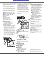
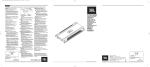
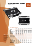
(044)361-05-06
ICQ:495-089-192
(067)469-02-12
ICQ:613-211-859
(099)048-99-03
(093)672-77-76
User's Manual
Car amplifier JBL GTO24001 1-channel
In the online store Winauto you also can buy сar amplifier JBL GTO24001 . Delivery in Kiev and throughout Ukraine
with payment upon receipt!
http://winauto.ua
Car Receivers - Facia Plates - Head Units - TV and Monitors - Car Antennas - Car Audio - Car DVRs - GPS Navigation - Trip Computers - Security
Systems - Mechanical Locking - Car Park Systems - Cameras - Optic and Light - Car Tuning - Car Heating - Marine Audio and Electronics - Car
Accessories - Car Isolation - Car Installation Components - Car Batteries - Liquid and Oil -
Car audio and car goods internet store Winauto
GTO24001
w
in
au
to
.u
a
OWNER’S MANUAL
Car audio and car goods internet store Winauto
1x
1x
24-13/16"
630mm
2-1/8"
53mm
in
au
to
.u
a
10-3/8"
263mm
w
Optional RLC
1"
25mm
A B
A
B
C
D
1-5/8"
40mm
A
Car audio and car goods internet store Winauto
GTO24001 CAR AUDIO SUBWOOFER AMPLIFIER OWNER’S MANUAL
Distribution Block
a
0-Gauge
(0 AWG,
53.5mm2)
4-Gauge
(4 AWG,
22mm2)
0-Gauge
(0 AWG,
53.5mm2)
Fuse Holder
300A
Battery
Inside Engine Compartment
Power Input Connectors
• +12V: See ”Fuse Holder“ .
• GND: Connect to the vehicle’s chassis using
4-gauge (4 AWG, 22mm2) wire. Refer to Figure 3.
w
Speaker Output Connectors
• Connect the speakers to these terminals,
observing proper polarity. Either + or –
terminal may be used. Minimum total
impedance is 2 ohms.
Fuse Holder/+12V Connection
• Replace fuse only with the same type and rating.
• Mount the fuse holder within 18" (45cm) of the
vehicle’s battery, inside the engine compartment, and connect one end of the fuse holder
to the battery’s “+” terminal using a single piece
of 0-gauge (0 AWG, 53.5mm2) wire, as shown in
Figures 1 and 2.
• For normal installation, connect two pieces of
4-gauge (4 AWG, 22mm2) wire to the other end of
the fuse holder, as in Figure 1. Route both pieces
of 4-gauge (4 AWG, 22mm2) wire through the car,
using rubber grommets in all locations where
the wire must pass through metal. Connect the
other end of the 4-gauge (4 AWG, 22mm2) wire to
the two “+” terminals on the amplifier’s power
connectors
(refer to illustrations page).
Figure 2.
to
.u
Specifications
• 1700W RMS x 1 channel @ 4 ohms and ≤1% THD + N*
• 2400W RMS x 1 channel @ 2 ohms, 14.4V supply and
<1% THD + N*
• Frequency response: 20Hz – 330Hz (–3dB)
• Maximum input signal: 6V*
• Maximum sensitivity: 200mV*
• THD + N: 0.5%
• Signal-to-noise ratio: 65dBA
(reference 1W into 4 ohms)*
• Signal-to-noise ratio: 97dBA
(reference rated power into 4 ohms)
* CEA-2006A-compliant
• For competition installations, replace the fuse
with a 300A ANL (not included). Connect a single
piece of 0-gauge (0 AWG, 53.5mm2) wire to the
other end of the fuse holder, as in Figure 2.
Route the 0-gauge (0 AWG, 53.5mm2) wire
through the car, using rubber grommets in all
locations where the wire must pass through
0-Gauge
metal. Connect the other end of the 0-gauge
(0 AWG,
2
(0 AWG, 53.5mm ) wire to the input terminal
of a
53.5mm2)
power distribution block (not included) designed
4-Gauge
2
to AWG,
accept 0-gauge
(0 AWG,
Fuse
Holder53.5mm ) wire.
(4
Connect
of 4-gauge (4 AWG, 22mm2)
22mm2) two pieces 150A
wire to the distribution block and connect the
other ends of the wire toBattery
the two “+” terminals
on the amplifier’sInside
powerEngine
connectors
(refer to
Compartment
illustrations page).
in
au
Installation Warnings and Tips
• Disconnect the negative (–) lead from your vehicle’s
battery.
• At the installation sites, locate and make a note of
all fuel lines, hydraulic brake lines, vacuum lines
and electrical wiring. Use extreme caution when
cutting or drilling in and around these areas.
• Choose a safe mounting location away from moisture.
• Make sure there is sufficient air circulation at the
mounting location for the amplifier to cool itself.
• Mount the amplifier, using the supplied hardware.
Figure 3.
Factory Bolt
Ring Connector
DBO (Dynamic Bass Optimization) Variable
Subsonic High-Pass Filter With Variable Boost (Q)
• For woofers in tuned (vented) enclosures, set
the Frequency control to a value 10Hz below the
enclosure’s resonance (tuned) frequency.
• For woofers in sealed boxes, set the control to
any value you prefer, between 30Hz and 50Hz.
• Set the Boost control according to your
preference, being careful not to apply
enough boost to damage your woofer(s).
A DBO High-Pass Filter Frequency control,
variable between 10Hz and 100Hz. See
above for appropriate settings.
B DBO Boost control provides up to
12dB of boost, slightly above the highpass filter’s frequency. See above for
appropriate settings.
Optional Remote Level Control (RLC) Connector
• Connect the Remote Level Control (RLC) here,
using the RJ-11 cable (supplied with the RLC).
Power On LED
• Illuminated when the amplifier is on.
Protect LED
• Illuminated under any of the following fault
conditions: battery over/under voltage, short
circuit in speaker wires, amplifier is too hot,
amplifier’s output circuit has failed (DC voltage
is present in the amplifier’s output).
Setting Input Level
A Turn Input Level control counterclockwise to
6V (minimim).
B With a dynamic music track playing, turn the
head unit’s volume control to the 3/4 position.
C Turn Input Level control clockwise until the
bass output is proportionate to the output of
the high-frequency speakers, according to
your preference.
D Input level is now adjusted correctly.
Setting the Crossover
A Crossover setting for subwoofers.
Note: Acceptable frequency ranges are indicated
in gray.
Remote Level Control (Optional)
The Remote Level Control, if installed, will allow
you to adjust the level of bass while seated in the
listening position.
Ground Wire
Figure 1.
Note: Remove any paint
below ring connector.
4-Gauge
(4 AWG,
22mm2)
0-Gauge
(0 AWG,
53.5mm2)
Fuse Holder
150A
Battery
Inside Engine Compartment
Distribution Block
Star Washer
• REM: Connect to the “Remote Out” lead from
the source unit or to a source of switched
12V+ (ACC).
Aux Output Connectors (RCA)
• Nonfiltered pass-through output. Connect to the
input of an additional amplifier.
Input Connectors (RCA)
• Connect to the RCA outputs from the source unit
or signal processor.
Input-Level Control
• Used to match the input level of the amplifier
to the output level of the source unit.
• See for the adjustment procedure.
Low-Pass Filter Frequency Control
• 12dB/octave low-pass filter,
variable from 32Hz to 320Hz.
for the adjustment procedure.
• See
This product is designed for mobile applications and is not
intended for connection to the mains.
A valid serial number is required for warranty coverage.
Features, specifications and appearance are subject to change
without notice.
w
in
au
to
.u
a
Car audio and car goods internet store Winauto
Declaration of Conformity
Harman International, Consumer Division
8500 Balboa Boulevard, Northridge, CA 91329 USA
www.jbl.com
© 2009 Harman International Industries, Incorporated. All rights reserved.
JBL is a trademark of Harman International Industries, Incorporated,
registered in the United States and/or other countries.
Part No. GTO24001OM 7/09
www.jbl.com
We, Harman Consumer Group, Inc.
2, route de Tours
72500 Château du Loir
France
declare in own responsibility that the product described in this owner’s
manual is in compliance with technical standards:
EN 55013:2001+A1:2003
EN 55020:2002+A1:2003
Klaus Lebherz
Harman Consumer Group, Inc.
Château du Loir, France 12/08