1
US 20070288860A1
(19) United States
(12) Patent Application Publication (10) Pub. No.: US 2007/0288860 A1
Ording et al.
(54)
(43) Pub. Date:
USER INTERFACE FOR PROVIDING
Dec. 13, 2007
Related US. Application Data
CONSOLIDATION AND ACCESS
(63)
Continuation of application No. 09/467,074, ?led on
Dec. 20, 1999.
(75) Inventors: Bas Ording, Sunnyvale, CA (US);
Steven P. Jobs, Palo Alto, CA (US);
Donald J. Lindsay, Mountain View,
CA (Us)
Publication CIaSSi?CatiOH
(51) Int. Cl.
G06F 3/048
(52)
US. Cl.
(2006.01)
............................................................ .. 715/779
Correspondence Address:
BUCHANAN, INGERSOLL & ROONEY PC
(57)
ABSTRACT
POST OFFICE BOX 1404
.
ALEXANDRIA, VA 223134404 (Us)
.
.
.
Methods and systems for prov1d1ng graphical user mterfaces
are described. To provide greater access and consolidation to
frequently used items in the graphical user interface, a
(73) AssigneeZ Apple Inc_
userbar is ‘established Which includes a plurality'of item
representations. To permit a greater number of 1tems to
reside in the userbar, a magni?cation function can be pro
(21) App1_ NQ;
11/892,153
(22) Filed:
Aug. 20, 2007
vided Which magni?es items Within the userbar When they
are proximate the cursor associated With the graphical user
interface.
[I File Edit Image Luyer Select Filter View Window (:3
'UFO Newsletter
W3
Atomic Sonic
[ 500
Clock
——i
[n ® @
630
@im
/
)
670
620
540
Patent Application Publication Dec. 13, 2007 Sheet 1 0f 6
US 2007/0288860 A1
75
'
f/
w .
fFILE EDIT VIEW SPECIAL COLOR
r65
74
MY DOCUMENTS
r50
W
55 T
DOCUMENT 1
DOCUMENT 3
57\?
qqs
DOCUMENT 2
DOCUMENT 4
T
-
T
. )X
70']
50
/
20
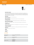
FIG. 1A (PRIOR ART)
75
~
20
\
I
F
‘FILE EDIT v1Ew SPECIAL COLOR
'
F55
74 \?: MY DOCUMENTS
55
DOCUMENT 1
'
:5 50% DE 5,
MY DISK
DOCUMENT 5
F60
Q55
DOCUMENT 3
W57
47
\
"'
I W58
10 J
42 H
1/‘
30
59 '—-—:
WIP
'
FIG. 1B (PRIOR AR T)
1111
TRASH
‘i
Patent Application Publication Dec. 13, 2007 Sheet 2 0f 6
\200
f 210
2.30
/
220
Stortl‘HWord Proc.l/ Drawing Prog.|§8preod Sheetl
FIG. 2 (PRIOR ART)
Workspace
Window
Edit
Files
Optical
Uti ities
-lice
~
Loq Out
D
D
D
D
>
Directory Browser
570
A
V
A
V
A
FIG. 3. (PRIOR ART)
US 2007/0288860 A1
Patent Application Publication Dec. 13, 2007 Sheet 3 0f 6
{401
{402
RANDOM
US 2007/0288860 A1
{403
'
{404
READ
DA TA
PROCESSOR
ACCESS
MEMORY
ONLY
MEMORY
STORAGE
DEVICE
l
|
|
l
/
l
|
I
|
ALPHA-
CURSOR
SIGNAL
NUMERIC
00N7P0L
GENERATION
INPUT DEVICE
DEVICE
DEVICE
400
Dljrg?fgg
L405
L406
L 407
FIG. 4
512
(
A
0
\
I506
\
k
j
/
\"/7\ 511
1:]
lI!
I'll
I l IIIIIII
I I I [Allllllllllll‘gll
l I l J j
l
.11!
.I!
13mm
‘l
L502
510
503
FIG. 5
|l\\\
‘1
L504
L408
Patent Application Publication Dec. 13, 2007 Sheet 4 0f 6
U0.5$.352 02
US 2007/0288860 A1
QC. 2E5Bm<
A
_\
V
‘ GE
m.
x86
0E32isU2::3i3Q:.2.5;2
_| ®E®E
Q53%9%Q2
Patent Application Publication Dec. 13, 2007 Sheet 5 0f 6
U
.
95532 6.2
8! 00%Hf
@
9
@
252‘205m
mu:
2:2a.
h.ombsw?nm
0U:32:2£5isE53%3.E6;2
5O;83 :@326“BO
. =25.
US 2007/0288860 A1
EoOs5uEc:moz
E
092=oEm4
@2u530m25c.1;0
0@253 $320
Patent Application Publication Dec. 13, 2007 Sheet 6 0f 6
I
H hi 2%7A///4/A2%///
800
FIG. 8A
H
800_
/
'
_
W
-_
w§i®§$
W.
67
FIG. 85
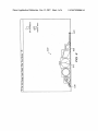
_d1 ~ d2 * 5/10.
r,
¢§\\\\\\\\N§®///
800'
FIG. 8C _
800
FIG. 80
670
US 2007/0288860 A1
V610
Dec. 13, 2007
US 2007/0288860 A1
USER INTERFACE FOR PROVIDING
CONSOLIDATION AND ACCESS
[0001] This is a continuation of application Ser. No.
09/467,074, ?led Dec. 20, 1999, the tents of Which are
incorporated by reference herein.
substantially the full display screen area When other Win
doWs are not open. The desktop is usually visible in the
background When other WindoWs are open.
[0007] Existing inside any particular WindoW, including
the desktop itself, are other information identi?ers called
“icons.” An icon is a screen identi?er associated With a
BACKGROUND
particular collection of computer information. Typically an
[0002] The present invention relates generally to graphical
icon may represent a “?le” Which is either a collection of
data or a program or program segment. An icon also may
represent the closed state of a WindoW. Icons are graphic
user interfaces for computer systems. More particularly, the
present invention relates to systems and methods for inter
facing applications and operating systems Which provide for
?exible customiZation of graphical user interfaces.
[0003] The evolution of the computer industry is unpar
alleled in its rate of groWth and complexity. Personal com
puters, for example, Which began as little more than feeble
calculators With limited memory, tape-driven input and
monochrome displays are noW able to tackle almost any data
processing task. While this meteoric increase in poWer Was
almost suf?cient to satisfy the demand of application design
ers and end users alike, the corresponding increase in
complexity created an ease-of-use problem Which the indus
try Was someWhat sloWer in solving. Thus, designers Were
faced With a neW challenge: to harness this computing poWer
in a form usable by even those With relatively little computer
training to smooth the transition of other industries into a
computer-based information paradigm.
[0004] As a result, in the early to mid-l980’s many neW
I/O philosophies, such as “user friendly”, “WYSIWYG” and
“menu driven” came to the forefront of the industry. These
concepts are particularly applicable to microcomputers, also
knoWn as personal computers, Which are intended to appeal
to a broad audience of computer users, including those Who
previously feared and mistrusted computers. An important
aspect of computers Which employ these concepts Was, and
continues to be, the interface Which alloWs the user to input
commands and data and receive results, Which is commonly
referred to as a graphical user interface (GUI).
images displayed on the computer screen and usually cor
respond to the type of information stored Within the ?le.
Icons give the user access to the particular ?le represented
by the graphic image When the icon is visible. The use of
icons and WindoWs is Well knoWn in the art.
[0008] The “?le” is the information packet that the user
Wishes to utiliZe, create or modify; each particular ?le has an
associated name identifying the ?le. Therefore, any given
?le may be located in the information management system
by knoWing a ?le name, an iconographic representation
associated With the name, or a WindoW locator name. All
information (?les) situated Within a particular WindoW are
identi?ed With that particular WindoW’s oWn identi?cation
location Within the computer information management sys
tem. Therefore, any particular ?le information can be
retrieved knoWing its particular identi?cation name and its
WindoW name. Accordingly, the resulting screen display
utilizing the FinderTM user interface may be broken doWn
into multiple WindoWs and graphic icons.
[0009] Another important element of this (and other)
conventional user interfaces is a screen cursor. The cursor
alloWs direct user control over the user interface as
described above. The FinderTM user interface is comple
mented With a “mouse” and a corresponding “pointer”
Which makes up the cursor control device. The user has
control over the mouse, Which is an electromechanical
device that translates tWo-dimensional mouse movement
into a tWo-dimensional screen position movement repre
The success of this type of interface is evident from
sented by, for example, a pointer or arroWhead. The user
the number of companies Which have emulated the desktop
contacts and directs the mouse. When the mouse is moved
freely on a table top, then the pointer on the screen Will move
in a similar and proportional manner. The mouse also
contains one or more push buttons Which can be used to
[0005]
environment. Even successful concepts, hoWever, must con
tinually be improved in order to keep pace With the rapid
groWth in this industry. The advent of multimedia, especially
CD-ROM devices, has provided vast quantities of secondary
storage Which have been used to provide video capabilities,
e.g., live animation and video clips, as regular components
of application displays. With these and other neW resources
at their disposal, application designers and users alike,
effectuate control over the cursor pointer by selecting or
deselecting speci?c icons or other display tools. It is said
that the cursor pointer is “activated” When the mouse button
is depressed and the pointer remains active until the button
is released. Pointer activation may also be initiated by
demand additional functionality and greater ease of use from
sequences of mouse button presses, such as a “double click”
the desktop environment.
interaction Which involves rapidly pressing the mouse but
[0006]
To consider the challenges associated With continu
ton press tWice in sequence.
ing GUI design, consider as an example of a GUI Which has
[0010]
evolved over time the FinderTM user interface and informa
face system for a display management system is therefore
based on WindoWs, icons and pointer movement of the
tion management system (simply “FinderTM user interface”
hereafter) Which runs on the Apple MacintoshTM computer.
The FinderTM user interface is based on the aforedescribed
display principles using “Windows” and “icons” to help
manage computer information. The main or root WindoW is
Access to information in a conventional user inter
cursor. To access a ?le, the cursor pointer is placed on the
visible icon or visible ?le name and the pointer is activated.
A closed WindoW may be represented by an icon or a
WindoW name. A WindoW opens When the pointer of the
called the “desktop” area, or more generally the primary
cursor rests on the visible icon or visible name representing
display region. The desktop, or primary display region, is
the closed state of the WindoW and the pointer is activated.
Within the open WindoW, ?les may be displayed by icon or
by name. An open WindoW, of various geometries, may be
alWays open (displayed on the screen With its contents
accessible or at least partially accessible), and takes up
Dec. 13, 2007
US 2007/0288860 A1
rectangular and Will exist Within the display area of the main
vieWing screen on the desktop. Multiple WindoWs may be
open at one time, typically With the most foreground Win
doW corresponding to the most recently opened WindoW and
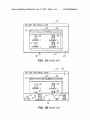
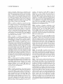
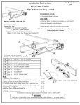
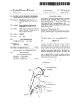
75 having a desktop area 20 With the Desk DraWer closed,
Wherein only the handle 10 of the Desk DraWer is visible. An
open WindoW 60 containing several document icons 55-58
Which are, therefore, accessible for operations by the user
the background WindoWs representing those opened previ
ously. In the organiZation scheme described, it is appreciated
via cursor 50. The WindoW 60 also includes a WindoW title
that ?les are nested Within WindoWs and WindoWs can be
nested Within other WindoWs; the main or root WindoW being
the desktop area, or primary display region.
[0011]
During a session using a WindoW-based informa
tion system, many WindoWs can be open at one time With
many displayed icons Within. WindoWs may overlap and
partially, or entirely, hide other WindoWs or icons. What
results is that the particular information the user Wants to
obtain may be hidden behind several layers of WindoWs and
may be di?icult to access; When an icon is hidden by another
WindoW it is temporarily not accessible. This has been
referred to in the industry as the “WindoW overlap” problem.
There are several instances Where WindoW overlap problems
routinely arise in the usage of conventional user interfaces.
A feW of the more troublesome scenarios are described
beloW.
[0012]
In order to complete a task, often the user must
access a single icon Within an open WindoW that exists in the
background, that is, covered or partially covered by other
WindoWs. The desired icon (“target” icon) Within the Win
?eld 65 and WindoW select region 74.
[0015] When activated, e.g., by placing cursor 50 over
handle 10, the Desk DraWer “opens” to reveal its contents.
In this case, icons 41, 42, 51 and 59 become visible. NoW
that these icons are visible, they too are available for
manipulation by the user via cursor 50. Thus, the Desk
DraWer concept provides a mechanism for placing fre
quently used icons in an out of the Way, yet easily accessible
location. The interested reader is directed to US. Pat. No.
5,657,049, entitled “Desk DraWer User Interface” for a more
in depth discussion of this technique, the disclosure of Which
is incorporated here by reference.
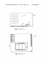
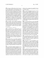
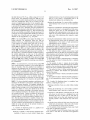
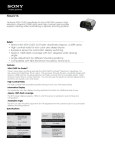
[0016] Another conventional GUI, i.e., that provided With
the WINDOWS 95 Operating System, tackles the problem
of desktop clutter by the provision of a taskbar to organiZe
concurrently running applications as shoWn in FIG. 2.
Therein, the desktop WindoW 200 includes a plurality of
icons 210 as Well as the taskbar 220. The icons 210 provide
“shortcuts” to applications or documents Which can be
invoked, e.g., by “double-clicking” on the desired icon. The
doW is no longer visible, and therefore not presently acces
taskbar 220 identi?es WindoWs Which are active including
both those Which are maximiZed and “minimized”, i.e., are
sible. The overlapping Windows or those that lay “on top of"
not currently displayed on the desktop 200. Each such active
the target WindoW must be closed or moved aWay
(“shu?led”) so that the target WindoW and target icon are
visible and thus accessible. WindoW shu?ling is time con
application is represented on the taskbar 220 by a corre
suming, confusing and often very tedious for the user. If
multiple routine icons need to be systematically accessed in
sequence then multiple WindoW shu?‘ling procedures may be
required.
[0013] Another WindoW overlap problem plaguing con
ventional user interfaces arises When the user requires tWo
icons to complete a task and each icon is Within a different
WindoW. The resulting screen display may contain several
open WindoWs from past tasks that may clutter the screen
display With unWanted information. This information may
obscure the desired WindoWs and icons. In many instances
the overlapping WindoWs are not unWanted, but hold the ?rst
of the desired icons in displayable vieW. In order to access
the second desired icon, the user may close the overlapping
WindoW that holds the ?rst icon, then gain access to the
second desired icon. Since the previously closed WindoW
holds the ?rst desired icon it must be opened again so that
the present task can be completed. Again, this process is
often time consuming and confusing for the user4espe
cially When the hidden second icon is one that is routinely
required. In this case the user is engaged in constant “Win
doW shu?ling” as described above.
[0014] Not surprisingly, these types of problems have
received a signi?cant amount of attention in recent years.
Several user interface products have been developed Which
provide different solutions to the manner in Which frequently
sponding button, Which typically has an iconic representa
tion of the application as Well as some descriptive text. As
neW applications are launched, representative buttons Will
be added to the taskbar 220, from left to right. Each existing
button Will be scaled in length to permit the taskbar to
accommodate neW buttons. To “maximize” an application
residing on the taskbar 220, the user can single click on the
representative button. Another feature sometimes seen in
this type of conventional GUI are application bars, e.g.,
appbar 230. Appbar 230 typically includes a number of
smaller buttons (relative to the length of buttons on the
taskbar When only a feW applications are resident there),
Which buttons can be depressed to launch a currently inac
tive application.
[0017] This conventional GUI, hoWever, suffers from the
draWbacks of having a rather rigidly structured layout (e.g.,
the user cannot select or organiZe the order of the buttons on
the taskbar 220) and from dif?culties in handling the rep
resentation of a large number of applications. As more
buttons are added to the taskbar 220, each individual button
becomes smaller. When, for example, betWeen 20-30 appli
cations have been launched and minimiZed, the taskbar 220
begins to add neW buttons as a second layer rather than
continuing the line of buttons illustrated in FIG. 2. To reach
the second layer, the user must toggle the taskbar 220, i.e.,
not all of the buttons are visible simultaneously on the GUI.
As the poWer of computers and number of interesting
applications, documents and other objects increases, it is
anticipated that users Will Wish to have ready access to a
used and currently active desktop objects are handled by the
GUI. For example, consider the conventional GUI depicted
in FIGS. 1(a) and 1(b). Therein, a “Desk DraWer” concept
groWing number of objects and, therefore, Will ?nd the
approach depicted in FIG. 2 to be annoying and ineffective.
is implemented to provide selectively hideable access to
[0018] Another conventional GUI Which attempts to solve
this particular problem can be found in the NeXTTM Oper
frequently used desktop objects. FIG. 1(a) depicts the screen
Dec. 13, 2007
US 2007/0288860 A1
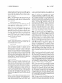
ating System. As illustrated in FIG. 3, and further described
in US. Pat. No. 5,146,556, entitled “System and Method for
speci?ed contents of the userbar, in particular minimiZed
an application “dock”300 including a column of icons on the
right side of the screen 310. The dock 300 is described as
WindoWs, to be presented at a larger siZe and in greater detail
and legibility than other objects in the userbar. This feature
permits, among other things, the individual tiles of the tool
to retain their legibility and prevents the user interaction
With the tool from being compromised by the scaled con
providing a visible mechanism for starting applications.
tents.
Managing Graphic Images” (the disclosure of Which is also
expressly incorporated here by reference), this GUI provides
Icons can be added and deleted to the application dock 300
by dragging them into a desired location proximate the
docking area, at Which time the operating system Will
integrate them into the dock 300.
[0019] Although someWhat more ?exible in terms of
alloWing the user to organiZe its content than the taskbar/
appbar of FIG. 2, the application dock 300 still suffers from
its limitations in terms of the number of applications Which
BRIEF DESCRIPTION OF THE DRAWINGS
[0024] These and other objects, features and advantages of
the present invention Will be readily understood by those
skilled in the art by reading the folloWing detailed descrip
tion in conjunction With the draWings, in Which:
[0025]
FIGS. 1(a) and 1(b) depict a ?rst, conventional user
can be docked at any one time. The icons in the dock are of
interface;
a ?xed siZe and, according to the user manual, are therefore
limited to a maximum of 13 Which can be included in the
[0026] FIG. 2 depicts a second, conventional user inter
face Which employs a taskbar and an appbar to handle
dock at any one time.
objects;
[0020] Thus, it can be seen that there remains a need in the
art to design a GUI Which provides the user With a larger
Which employs an application dock;
degree of ?exibility in terms of both the layout of the tool
Which manages these types of frequently used objects, as
Well as permitting a larger number of such objects to be
managed and simultaneously displayed.
SUMMARY
[0027]
FIG. 3 depicts a third, conventional user interface
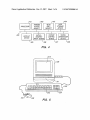
[0028] FIG. 4 is a block diagram of an exemplary system
in Which the present invention can be implemented;
[0029]
FIG. 5 is an exemplary computer system Which
may contain the functional blocks of FIG. 4 and in Which the
present invention can be implemented;
[0021] According to exemplary embodiments of the
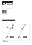
[0030]
present invention, these and other drawbacks and dif?culties
bar according to an exemplary embodiment of the present
of conventional GUIs are overcome by providing a simple,
invention;
consolidated and easily extensible facility for handling, for
example, frequently used objects. For example, user inter
[0031] FIG. 7 depicts the user interface of FIG. 6 With the
cursor disposed at another location Within the userbar region
faces according to the present invention provide a tool
(referred to herein as the “userbar”) Which consolidates
FIG. 6 illustrates a user interface including a user
on the screen; and
features including: launching and managing running appli
[0032] FIGS. 8(a)-8(d) describe an exemplary magni?ca
cations; opening and managing documents and their asso
tion effect mechanism according to an exemplary embodi
ment of the present invention.
ciated WindoWs; accessing control strip functionality; navi
gation to all types of uniform resource locators (URLs); and
status and noti?cation on running processes.
DETAILED DESCRIPTION
[0022] As mentioned above, existing tools of this type,
[0033] In the folloWing description, for purposes of expla
such as taskbars and docks, are constrained in one or more
nation and not limitation, speci?c details are set forth, such
of at least tWo Ways: having a rigidly structured layout and
being limited in the number of objects that they can repre
as particular circuits, circuit components, techniques, etc. in
order to provide a thorough understanding of the present
sent in the available screen space. With respect to layout, the
userbar according to the present invention is designed so that
the organization of the userbar is in the hands of the user. For
example, the tiles that represent the individual items in the
userbar can be reorganiZed at Will. There is virtually no
invention. HoWever, it Will be apparent to one skilled in the
art that the present invention may be practiced in other
embodiments that depart from these speci?c details. In other
structure enforced on the user, With the exception of tWo
description of the present invention.
“bookends” Which de?ne boundaries of the facility.
[0023] With respect to screen space, the userbar according
to the present invention provides a method for scaling the
entire contents of the object handling facility such that
literally upWards of ?fty objects (or more) can be accom
modated in a single, visible structure. As the objects handled
by the userbar become rather small, e.g., due to the siZe set
by the user or due to a large number of objects being added
thereto, it naturally becomes more dif?cult to distinguish
betWeen different tiles. Accordingly, exemplary embodi
ments of the present invention provide a magni?cation
effect, also referred to herein as a ?sheye effect, for broWsing
the scaled contents of the userbar. This mechanism alloWs
instances, detailed descriptions of Well-knoWn methods,
devices, and circuits are omitted so as not to obscure the
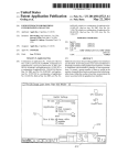
[0034] Exemplary embodiments of the present invention
can be implemented on an Apple MacintoshTM computer
system using the FinderTM user interface. HoWever, it Will be
readily appreciated by those skilled in the art that user
interfaces and elements of user interfaces according to the
present invention can be used in combination With any
system having a processor and a display. In general, such
computer systems, as illustrated in block diagram form by
FIG. 4, comprise a bus 400 for communicating information,
a processor 401 coupled With the bus for processing infor
mation and instructions, a random access memory 402
coupled With the bus 400 for storing information and
instructions for the processor 401, a read only memory 403
Dec. 13, 2007
US 2007/0288860 A1
coupled With the bus 400 for storing static information and
instructions for the processor 401, a data storage device 404
Userbar Contents
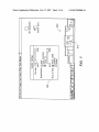
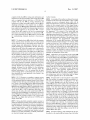
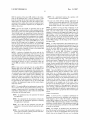
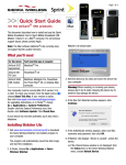
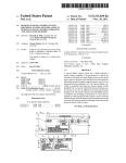
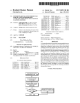
[0038] An example of the userbar according to the present
such as a magnetic disk and disk drive or CD ROM drive
invention can be seen in the user interface of FIG. 6. Other
coupled With the bus 400 for storing information and
instructions, a display device 405 coupled to the bus 400 for
displaying information to the computer user, an alphanu
examples are seen in subsequent ?gures Which Will be
further described beloW. Therein, the userbar 600 includes a
meric input device 406 including alphanumeric and function
keys coupled to the bus 400 for communicating information
and command selections to the processor 401, a cursor
control device 407 coupled to the bus for communicating
information and command selections to the processor 401,
and a signal generating device 408 coupled to the bus 400
for communicating command selections to the processor
401.
[0035] The display device 405 utiliZed With the computer
system and the present invention may be a liquid crystal
device, cathode ray tube, or other display device suitable for
creating images and alphanumeric characters (and ideo
graphic character sets) recognizable to the user. The cursor
control device 407 alloWs the computer user to dynamically
signal the tWo dimensional movement of a visible symbol
(cursor) on a display screen of the display device 405. Many
number (in this example sixteen) of tiles aligned along a
bottom portion of a user interface, the magni?cation level of
Which varies based on the position of the cursor 610 in a
manner to be described beloW in the section entitled “User
bar Appearance”. The contents of the userbar 600 may
represent a user-selected (or alternatively, an application or
operating system selected) set of “super-favorite” items, i.e.,
items that the user has determined deserve greater ease-of
access than their broader collection of favorite items, Which
could be numerous. The straightforward con?guration
mechanism of the userbar 600 according to the present
invention facilitates frequent changes to its contents, Which
contents are based on a user’s preferences and Will, there
fore, naturally vary from one user to the next. Any type of
item or object may be handled by the userbar 600, hoWever
a feW examples, including applications, document ?les and
WindoWs Will noW be described in order to illustrate hoW
implementations of the cursor control device are knoWn in
exemplary userbars according to the present invention may
represent and manipulate various items.
the art including a trackball, mouse, joystick or special keys
on the alphanumeric input device 406 capable of signaling
[0039] Applications can be presented on the userbar 600
by, for example, one of tWo methods. First, the application’s
movement of a given direction or manner of displacement.
It is to be appreciated that the cursor also may be directed
icon can be added to the userbar 600 as a permanent ?xture,
and/or activated via input from the keyboard using special
keys and key sequence commands. Alternatively, the cursor
e.g., for most frequently launched applications. Altema
tively, the application may not be a permanent ?xture of the
userbar 600, but may be added thereto because it is currently
preferred embodiment, it is to be assumed that the input
running. Such non-permanent applications may be repre
sented in the userbar 600 only While the application remains
running and may be removed automatically by the GUI
When the application is terminated. Faceless background
applications, e.g., virus protection applications, if not
cursor directing device or push button may consist any of
those described above and speci?cally is not limited to the
the userbar 600 While they are running. Similarly, applica
may be directed and/ or activated via input from a number of
specially adapted cursor directing devices, including those
uniquely developed for the disabled. In the discussions
regarding cursor movement and/or activation Within the
launched from the userbar 600, need not be represented on
mouse cursor device.
tion sub-processes, such as a Finder copy, need not appear
as a separate application tile on the userbar 600.
[0036]
[0040]
FIG. 5 illustrates an exemplary computer system
Document ?les can also be placed on the userbar
that in Which the present invention can be implemented. It
Will be appreciated that this computer system is one of many
computer systems that may can include the present inven
600. This includes, for example, editable, non-editable (i.e.,
read only) and stationary ?les. An application’s “set” ?les
tion. Therein, a keyboard 500 With keys 502 and keypad 504
userbar 600, but may only be useful to the user as part of the
userbar 600 if selecting one of these tiles Would initiate a set
change. A user may choose to place multiple copies of a
document onto the userbar 600, but the userbar 600 Will
is attached to the computer 506 along With a mouse device
508 and mouse push button(s) 510 for controlling the cursor.
The mouse device 508 and push button 510 make up a cursor
control device 407. It Will be appreciated that many other
(e.g., Location Manager sets) can also be placed on the
preferably only include a single representation of each
devices may be used as the cursor control device 407, for
instance the keyboard 500 may be substituted for the mouse
a folder is disposed on the userbar 600 and the user opens
device 508 and button(s) 510 as just discussed above. The
that folder, this can result in the ?le management system
computer 506 also typically contains a one or more media
object in a particular state. For example, if a tile representing
(e.g., Finder) opening (or navigating to) the directory rep
drives 511 (e.g., ?oppy disk, hard disk or CD ROM) and a
resented by the folder. If the user then minimiZes that ?le
display screen 512.
management system WindoW, the originating userbar object
[0037] Having described exemplary computer systems in
is then presented on the userbar 600 as a minimiZed WindoW
Which user interfaces according to the present invention can
be implemented, the discussion noW turns to a description of
(e.g., as a folder icon). LikeWise, if a document is opened
from the userbar 600 and its WindoW is subsequently mini
miZed by the user, it is preferable that a representation of the
such user interfaces. According to exemplary embodiments
of the present invention, a userbar is provided to the user
interface Which solves many of the problems described
above With respect to conventional user interface tools and
ing document’s tile, rather than adding a second tile to the
userbar 600 for that object.
facilities by providing extensibility, scalability and ?exibil
[0041] Document WindoWs, When minimiZed by the user,
ity Which are lacking in prior systems.
are placed on the userbar 600 and remain there until either
minimized WindoW replace the image used for the originat
Dec. 13, 2007
US 2007/0288860 A1
closed or maximized, Which process is described in more
example, a tile disposed in userbar 600 can change its
detail below under the section entitled “Userbar Function
appearance as it moves from one state, e.g., selected, to
another state, e.g., open or o?line. This alloWs the user to
ality”. The image appearing on the tile can be, for example,
either: 1) a dynamically scaled representation of the actual
WindoW contents, or 2) an appropriate image provided by,
for example, the application, such as the WindoW’s proxy
icon. For example, a minimiZed Finder WindoW might more
appropriately be presented as a folder icon, e.g., icon 620 in
userbar 600, as opposed to providing a scaled image of the
Finder WindoW’s content on the userbar 600.
[0042]
In addition to applications, documents and Win
doWs, many other types of items may reside on userbar 600.
For example, any type of system-supported uniform
quickly recogniZe the current state of each of the items on
the userbar 600. Currently executing applications can be
indicated by, for example, placing an LED-like indicator
graphic above or beloW the corresponding application’s tile
or icon. Applications can also supply additional tile images
to be substituted for, or composited on, the running appli
cation’s tile in the userbar 600. For example, an e-mail
application’s tile can present the number of neW messages,
superimposed over the application’s icon.
resource locator (URL) ?le types can be placed on the
[0046] According to exemplary embodiments of the
present invention, the default position of the userbar 600 is
userbar 600 including, but not limited to, ?le types having
the extensions: http, ftp, neWs, mailto, at, afp and ?le.
Additionally, developer-de?ned preference or setting mod
ules (e.g., a slider control to adjust the computer’s speaker
anchored to the bottom of the main monitor and centered
horiZontally therein. Thus, the userbar 600 maintains a
position aligned relative to the horiZontal center of the
screen, regardless of the number of items or tile placed in the
volume) can be added to the userbar 600 by the user. Adding
such preference or setting modules to the userbar 600 may
the user may or may not be permitted to relocate the userbar
be accomplished by, for example, dragging pre-de?ned
600 from its default position.
userbar 600. Depending upon the desired implementation,
objects from the Finder to the bar.
[0043] According to exemplary embodiments of the
present invention, tWo items are permanent ?xtures of the
userbar 600. These items, denoted by reference numerals
630 and 640, act as “bookends” that contain the contents of
the userbar 600 betWeen them. Those skilled in the art Will
appreciate that the selection of speci?c tiles to act as
bookends may vary from implementation to implementation
of the present invention. HoWever, in the purely illustrative
exemplary embodiments described herein tile 630, Which
represents the Finder process and its WindoW list, is provided
as the left bookend of the userbar 600. This tile 630
represents the running Finder process and, according to this
exemplary embodiment, no other tiles may be placed on the
userbar 600 to the left of this object. Similarly, a tile 640
representing the trash object acts as the right bookend of the
userbar 600 in this exemplary embodiment. This tile may
replace any other iconic representation of the trash object on
the desktop GUI. Acting as the right bookend, the user Will
[0047] In terms of the siZe of the userbar 600, according
to this purely illustrative exemplary embodiment, the user
bar 600 has a default siZe of 64x64 pixels. This default
height may change at locations associated With the cursor
position as described beloW in the section entitled “Variable
Magni?cation of Userbar Tiles”. A gap of a feW pixels may
be provided betWeen the bottom of the userbar 600 and the
bottom of the screen to alloW WindoWs that are placed, or
dragged, beloW the height of the bar to remain partially
visible. Alternatively, the userbar may be provided at the
very bottom of the display space such that no gap exists. In
fact, the userbar 600 may be located in any desired space on
the display.
[0048] The userbar 600 is, according to these exemplary
embodiments, the topmost WindoW on the screen, i.e., all
other WindoWs appear behind the userbar 600. Applications,
When creating or Zooming document WindoWs, should place
the bottom of the document WindoW above the top of the bar
not be able to place any other tiles on the userbar 600 to the
so as not to obscure any portion of the WindoW With the
right of this object.
userbar 600 Which Would otherWise overlay the neWly
[0044] In addition to the tWo exemplary, permanent ?x
tures on the userbar 600 represented in this example by tiles
630 and 640, other prede?ned content may be placed on the
userbar 600 at either the user’s discretion or in a manner
Which is prede?ned by the GUI. Candidate items for such
permanent residency on the userbar 600 include, for
example, application folders, favorites, address book, clock,
created WindoW.
[0049] Each tile can have a label associated thereWith. For
example, in FIG. 6 the label “Clock” can be seen centered
above tile 610. Those skilled in the art Will appreciate that
the label could alternatively be displayed beloW the corre
sponding tile. According to exemplary embodiments of the
present invention, labels for each tile are only visibly
Web broWser and e-mail applications.
displayed on the monitor While the cursor is proximate the
Userbar Appearance
corresponding tile. For example, as the cursor moves into a
region associated With a particular tile, the label associated
[0045] Exemplary embodiments of the present invention
provide various mechanisms Which impact the appearance
With that tile is displayed. When the cursor moves out of this
of the userbar 600 in a manner Which is intended to aid in
visible or invisible, can do so in a manner Which makes them
achieving the aforementioned objectives of providing a
simple, consolidated and easily extensible facility for han
dling frequently used objects. The userbar 600 can be
present invention, When the cursor 610 enters the userbar
region, a fade in time of Zero milliseconds is provided,
implemented as a single horizontal roW of items, or “tiles”,
each of Which represent a particular object or process. Any
state Which is supported for each object or process in the
operating system should also be supported on the userbar
600 by providing a different appearance for each state. For
region, the tile label Will vanish. Tile labels, When made
appear to fade in or fade out. In current embodiments of the
although those skilled in the art Will appreciate that this
value may be changed. In fact, the fade in and fade out
values mentioned herein may be user changeable, e.g., using
the user preferences dialog box described beloW With respect
to FIG. 7.
Dec. 13, 2007
US 2007/0288860 A1
[0050]
As the cursor 610 continues to roll across tiles on
the userbar 600, the appropriate tile label fades in While the
previous tile label fades out. Current embodiments of the
present invention provide, hoWever, provide a value of Zero
milliseconds for fading in and fading out of the tile labels as
the cursor moves across the userbar 600. If the cursor 610
leaves the userbar 600, the last label presented persists for a
short period, e.g., 250 milliseconds, then fades out. Although
this exemplary embodiment of the present invention is
described in the context of only displaying a single label at
a time, those skilled in the art Will appreciate that this feature
of the present invention may be readily adapted to varying
implementations. For example, the tile labels associated
With the current tile over Which the cursor is positioned, as
Well as the tWo tiles to either side of the current tile, could
be simultaneously displayed. Again, the number of tile
labels being displayed may be user settable.
Which the cursor is resting can be magni?ed. The level
(percentage) of magni?cation of each tile can also be varied
in any desired manner.
[0055] At a more fundamental level, hoWever, it Will be
appreciated that this magni?cation permits one or more
selected tiles in the userbar 600, i.e, the tile Which is pointed
to by the cursor 610 as Well as tiles proximate to the cursor
610, to be readily vieWed and identi?ed even While other
tiles residing in the userbar 600 are possibly more di?icult
to distinguish. This magni?cation functionality, among other
techniques associated With user interfaces according to the
present invention, permits the userbar 600 to, on the one
hand, handle many more objects than Was possible in
conventional user interfaces in a single, simultaneously
vieWable manner While, on the other hand, alloWing the user
to readily identify and manipulate individual objects resid
ing on the userbar.
[0051] According to another exemplary embodiment of
[0056]
the present invention, in order to assist the user in managing
the userbar’s contents, separator tiles can be provided. These
colored or translucent separator tiles can be placed betWeen
existing tiles to provide a visual distinction betWeen groups
of tiles. For example, the separator tiles may be provided as
a half-Width tiles (e.g., 32 pixels) and/or quarter-Width tiles
certain tiles experience increased magni?cation, While other
(e.g., 16 pixels).
Variable Magni?cation of Userbar Tiles
[0052] As mentioned above, a signi?cant bene?t of the
present invention may be found in the ability to permit a
large number of tiles to reside in a single roW of the userbar
600. Of course, the number of tiles Which can ?t in the
userbar 600 in a single roW is dependent upon the screen siZe
and the siZe of each individual tile. Since screen siZes are
?xed, the only Way to increase the number of tiles in the
userbar 600 is to reduce their siZe. HoWever, at some
relatively small siZe, the images in each tile Win not be
distinguishable by the user. Exemplary embodiments of the
present invention address this problem by providing for
variable magni?cation levels as betWeen different tiles on
the userbar 600.
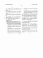
[0053] Referring again to the exemplary embodiment
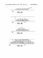
As the cursor 610 moves over the userbar 600,
tiles’ magni?cation decreases, based on their relative dis
tance to the current cursor position. Compare, for example,
FIG. 7 With FIG. 6. Although these tWo ?gures depict the
same userbar 600, i.e., With the same tiles residing therein,
the magni?cation characteristics dilfer. In FIG. 7, the cursor
610 noW rests over the tile entitled “8”. Some of the tiles
surrounding “8” are also magni?ed, While the “Clock” tile
has returned to its unmagni?ed state and is noW displayed at
a default siZe setting. The magni?cation effect can be
canceled When the cursor leaves the content region of the
userbar 600, as determined by the level of magni?cation
being applied (Which level is user-selectable as described
beloW). For example, if the default siZe of the tiles is 64
pixels, but the tile on Which the cursor is currently posi
tioned has been scaled up to 128 pixels due to the magni
?cation effect, then this effect Will not end until the cursor
leaves the 128 pixel top boundary of the userbar 600.
[0057] Also seen in FIG. 7 is an exemplary userbar
settings screen 620 Which permits the user to vary the tile
siZe, magni?cation characteristics and the shoW/hide char
acteristic of the userbar. This feature of exemplary user
interfaces according to the present invention Will be
illustrated in FIG. 6, it Will be seen that a cursor 610 rests on
described in more detail beloW.
top of one tile in the userbar 600, i.e., the tile having the
[0058]
descriptive legend “Clock” thereabove. It Will immediately
tion.
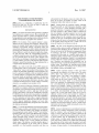
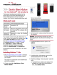
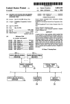
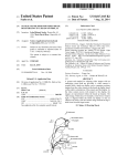
detailed example of a variable magni?cation function
according to the present invention Will noW be described.
Therein, each tile is placed along a reference baseline 800
(Which may be located in any position and With any orien
tation on the display). As seen in FIG. 8(a), each tile has the
same height h, but may have different Widths. FIG. 8(a)
shoWs the default display state of a group of tiles residing in
[0054] In this particular exemplary embodiment, not only
region, i.e., the variable magni?cation effect has not been
be recognized that the “Clock” tile on Which the cursor 610
rests has been magni?ed to be larger than the surrounding
tiles in the userbar 600. This magni?cation is attributable to
the “?sheye” effect Which can be provided to the userbar 600
according to exemplary embodiments of the present inven
is the tile upon Which cursor 610 rests magni?ed, but so are
surrounding tiles. The amount of magni?cation can vary as
With reference noW to FIGS. 8(a)-8(d), a more
userbar 600 When the cursor 610 is outside of the userbar
invoked.
betWeen tiles proximate the cursor position. In this example,
the magnitude of the magni?cation level is a function of the
[0059]
distance of each tile edge from the cursor 610. Of course
those skilled in the art Will appreciate that there are many
both or neither of these parameters may be user settable. For
different types of magni?cation techniques and algorithms
provides an example Wherein the user can select the scaling
height H via a slider. The effect Width de?nes a region
Wherein any tile that lies even partially Within W pixels to
either side of the cursor position Within the userbar region
Will be scaled. For example, as shoWn in FIG. 8(b), the
Which can be employed to provide this type of functionality.
For example, any number of tiles to either side of that over
Which the cursor is resting could experience some level of
magni?cation. Alternatively, only the individual tile over
To establish the variable magni?cation function, a
scaling height H and an effect Width W are chosen. Either,
example, the user preferences dialog box 720 in FIG. 7
US 2007/0288860 A1
darker tiles Will be scaled based on the cursor 610’s position,
While the lighter tiles on either end of the userbar 600 Will
not be scaled. The parameter W can be chosen to be a
multiple of the default tile Width, hoWever such a relation
ship is not required.
Dec. 13, 2007
or store a document by dragging it to an application or
folder, respectively, that resides on the userbar 600 as a tile.
[0064] As a navigator, the userbar 600 provides a method
for users to easily access, or navigate to, favorite “places”,
including but not limited to WindoWs. For example, accord
[0060] After determining the effect region based on W and
ing to exemplary embodiments, all system-supported uni
the cursor position, a scale amount S based on the effect
versal resource locators (URLs), as Well as local or remote
Width and change in height of the tiles is calculated accord
directories, can be placed on the userbar 600. HoWever in the
context of WindoWs, minimized WindoWs can be scaled and
added to the userbar 600. Minimized WindoWs can be
presented on the userbar 600, for example, as either thumb
nails of their content or by their WindoW proxy icon. For
example, the minimized WindoW of a Finder’s vieW of a
folder may be more appropriately shoWn as the folder icon
rather than a thumbnail of the WindoW’s content. Applica
ing to equation (1).
Tiles outside the effect region Will be shifted aWay from the
cursor position by the scale amount S, resulting in the
userbar 600’s Width increasing by up to 28.
[0061] When the cursor 610 enters the userbar region, tWo
distances (dl and d2) are calculated for each tile. More
speci?cally, for each tile the distance dl from the cursor
610’s position to the left edge of tile and the distance d2 from
tions’ icons on the userbar 600 can provide a contextual
menu of their open document WindoWs, thereby alloWing
users to select a speci?c WindoW to bring to the front.
in FIG. 8(0). If the value of either dl or d2 lies outside the
range {-W, W}, then the value is changed to be the closest
of —W and W. Scaled values dl' and d2‘ are then calculated
[0065] As a process manager, the userbar 600 provides a
method for users to identify and sWitch betWeen running
applications. For example, the userbar 600 Will permit users
to hide/unhide processes and perform other such actions
using the folloWing sine functions:
through contextual menus or modi?ed mouse clicks. An
the cursor to the right edge of the tile are calculated as seen
Each tile is then redraWn betWeen dl' and d2‘ having a size
Which is scaled equally in both Width and height from the
loWer left hand comer by a factor:
Those skilled in the art Will appreciate that the foregoing is
merely an illustrative example of a particular, yet still
exemplary, embodiment by Which a variable magni?cation
effect according to the present invention can be imple
mented. Moreover, although these exemplary embodiments
describe user interfaces Wherein the variable magni?cation
application’s status, e.g., not running, launching, running
and running but hidden, can also be indicated by the userbar
600, e.g., by changing an appearance, behavior or other
characteristic of the application’s representative tile on the
userbar 600. An application can update its status on the
userbar 600, resulting in a change in the appearance or
behavior of its representative tile. For example, a tile rep
resenting an e-mail application that is resident on the userbar
600 can be overlaid With a number representing the number
of neW messages in a user’s inbox. This number can be
updated and changed to re?ect changes in the status of the
in-box, e.g, increasing as neW messages are received in the
inbox or decreasing after the user revieWs his or her mes
sages.
[0066] In operation, according to this exemplary embodi
effect is invoked When the cursor moves into the userbar 600
region, i.e., When the cursor crosses a border of one of the
ment, all running applications Will appear on the userbar
tiles residing in the userbar 600, those skilled in the art Will
further appreciate that the magni?cation effect can also be
to the immediate right of the left bookend tile 630. If the tile
invoked earlier, e.g., When the cursor moves to Within some
predetermined distance of one of the tile borders.
Userbar Functionality
[0062] Having described examples of userbar contents and
appearance according to exemplary embodiments of the
present invention, the discussion noW turns to exemplary
techniques in Which the userbar 600 can be implemented to
provide desirable user interface functionality. According to
one exemplary embodiment of the present invention, the
600. When launched, these applications Will place their tiles
is left untouched While the application is running, then that
tile Will disappear from the userbar 600 once the application
is quit. If the user changes the position of the application tile
in the userbar 600 While the application is running, then the
tile is designated as a permanent resident of the userbar 600
and does not disappear When it has ?nished running.
[0067] Items can be added to the userbar 600 by dragging
them into the userbar’s content region. During a drag, if the
cursor 610 enters the region of the userbar 600, the userbar
600 Will expand, e.g., at the nearest point betWeen tWo
userbar 600 is not implemented as a container and, therefore,
existing tiles, to accommodate the item(s) being dragged.
it cannot “hold” ?le system objects. Therefore, an object
This permits neW items to be inserted at any position in the
placed on the userbar 600 by the user can be implemented
bar. While expanded, tile images of the items being dragged
as an alias to the corresponding ?le system, or source object.
can be visible in the bar in the positions they Would occupy
if dropped Within the bar. These can be displayed as trans
lucent “insert target tiles” to provide the user With an idea of
hoW the userbar 600 Would appear after dropping the items
onto the userbar 600 at that position.
This means that, for example, moving objects from the
userbar to the trash 640 Will not result in the source ?le being
destroyed.
[0063] The userbar 600 according to the present invention
has many functions and features including launching, navi
[0068] Having entered the userbar 600 during a drag, if the
gation and process management. The userbar 600 can also
cursor 610 continues across the userbar 600, the insert target
support drag launching and storage, e.g., the ability to open
tile(s) move, folloWing the horizontal position of the cursor
Dec. 13, 2007
US 2007/0288860 A1
610. The position of the cursor 610, relative to the center
point of the underlying tile, is used to determine at What
point the existing tile and insert target tiles sWap positions.
When item(s) are dropped, the actual tile image(s) repre
senting the item(s) replace their respective translucent insert
target tile(s). An animation sequence may be displayed to
reinforce this action.
[0069]
The user can reorder, or reposition items on the
userbar 600. As mentioned above, in this exemplary embodi
ment only tWo items, the Finder application tile 630 and the
Trash tile 640 cannot be repositioned. Instead, these tiles
remain as bookends, de?ning the boundaries of the userbar’ s
contents. Reordering items can be implemented in a straight
forWard manner by dragging an item (tile) to a neW position,
With similar graphical feedback being provided as for the
process of adding an item to the userbar 600. That is, When
removed the tile image can be changed to its translucent
insert tile image and, When reinserted into the userbar 600,
the tile Will reacquire the image associated With its current
state. Multiple items can be repositioned at the same time if
the user ?rst selects a plurality of items in the userbar 600
[0077]
On a minimized WindoW, this operation Will
cause the WindoW to be maximized
The user can sWitch betWeen running applications by
clicking on the desired application tile. This Will result
in that application, and all of its associated WindoWs,
being brought forWard in the WindoW layering order.
[0078] In addition to drag and drop con?guring of the
userbar 600, users can drag and drop ?les, and other userbar
items, onto tiles Which reside on the userbar 600. For
example, a document can be dragged and dropped onto a tile
representing a Word processing application in the userbar
600, resulting in the Word processing application being
launched and then opening the dropped document. Altema
tively, a ?le can be dropped onto a folder residing on the
userbar 600, resulting in the ?le being moved or copied to
the target folder.
[0079] As Will be appreciated by those skilled in the art, it
is useful to provide a mechanism Which permits the GUI to
distinguish betWeen an operation Wherein a user is adding an
item to the userbar 600 and an operation Wherein a user is
[0070] A selection of multiple tiles can be made by, for
dropping an item onto an existing tile Which is already
resident on the userbar 600. According to exemplary
embodiments of the present invention, a modi?er key,
example, de?ning that performing a shift-click on a tile Will
pressed anytime during the drag but prior to the drop, Will
only select that tile, With no further action occurring. If the
user maintains the shift key in a depressed state, additional
force a drop action in place of the normal insert action. This
modi?er acts as a toggle betWeen insert mode and drop mode
tiles can be selected. Subsequent dragging, initiated on one
drop.
and, if released during the drag, a drop Will result in an
default insert instead. Toggling the state of the modi?er key
Will result in the bar opening (to accept an insert) and
closing. During a modi?ed drag, eligible target tiles can be
highlighted to denote that they can receive the object type
[0071] Items can be removed from the userbar 600 by
dragging them to the trash tile 640, or to the desktop. The
the userbar 600, effectively broWsing for eligible targets.
prior to initiating a drag operation.
of the pre-selected tiles Will affect all selected tiles. If a
discontiguous selection of tiles is repositioned Within the
userbar 600, the selection Will become contiguous after the
being dragged. The user can continue to drag items across
trash tile 640 Will provide appropriate drop feedback (e.g.,
[0080]
sound and/or animation) When an item is dragged thereover.
As mentioned above, since the userbar 600 is preferably not
a container Which holds original source identi?ers, but
management solutions that are intended to alloW users to
make better use of limited screen space. For example,
instead only aliases (i.e., pointers), this operation Will only
tion, the userbar 600 does not provide direct access to all
delete the userbar representation of the item and not the
source object in the operating system. Alternatively, as Will
be appreciated by those skilled in the art, the userbar 600
open document WindoWs as only minimized WindoWs are to
be placed on the userbar. Access to a document WindoW
could also be implemented using real ?le system objects
rather than aliases.
[0072]
The userbar 600 can be implemented to permit the
user to interact With the items resident thereon through, for
example, a single mouse click. According to this exemplary
embodiment, single-clicking on tiles resident in userbar 600
Will produce the folloWing results:
The userbar 600 also provides a number of WindoW
according to exemplary embodiments of the present inven
menu associated With a tile resident on the userbar 600 can
be provided in, for example, one of tWo Ways. First, a
sub-menu can be displayed relative to each application tile,
the sub-menu listing all of that application’s open docu
ments. Second, a dedicated application tile can be added to
the userbar 600 Which tile provides a menu interface to all
open document WindoWs, grouped by their associated appli
cations.
Userbar Customization
[0073] On application tiles, this operation Will launch
the application.
[0074]
On a document tile, this operation Will open the
document With the appropriate application, launching
the application if necessary.
[0081] As shoWn in FIG. 7, exemplary embodiments of
the present invention provide techniques and mechanisms
Which permit a user to adjust the manner in Which the
userbar 600 is displayed on the screen. In this example, a
dialog box 720 is illustrated having a number of user settable
preferences available therein. These preferences permit the
[0075]
On a URL tile, this operation Will cause the
destination to be presented using the appropriate appli
user to tailor the appearance and behavior of the userbar 600
to suit his or her needs.
cation.
[0076]
On a control strip, the module’s interface (i.e. a
menu) Will be presented. Clicking outside of the inter
face Will dismiss the interface.
[0082] For example, as described above the default tile
size of the bar may be 64x64 pixels. The default value refers
to the size of a tile in its unmagni?ed state. HoWever, this
default value can be changed by the user, e.g., by adjusting
Dec. 13, 2007
US 2007/0288860 Al
Wherein activation of one of said representations in the
the slider shown in FIG. 7, e.g., Within a range of 16 to 128
pixels square. The preferences dialog box 720 may also
dock by a user causes a corresponding item to be
contain a set of controls Which permit the user to determine
launched and displayed in said display area;
When the magni?cation effect will be invoked and the
amount of magni?cation provided. In the exemplary pref
erences dialog box 720 illustrated in FIG. 7, a set of controls
is provided for this purpose including a radio button group
that permits the user to determine When the magni?cation
detecting the positioning of a cursor Within a predeter
mined distance from at least one of said representa
tions;
in response to said detection, increasing the representation
effect will be invoked and a slider that alloWs the user to set
closest to said cursor to a designated siZe While main
the maximum magni?cation level, e.g., that associated With
taining the aspect ratio of said representation, and
increasing other representations in said dock to siZes
the tile over Which the cursor 610 is currently positioned. Of
course the siZe of the magni?ed tiles should not be less than
the default siZe of the tiles and some upper limit may be
desirable for the magni?cation, e.g., 128 pixels.
[0083] The userbar 600 can also support the ability to be
hidden olfscreen. The preferences dialog box 720 can
Which are an inversely related to their distances from
said cursor, While maintaining their respective aspect
ratios; and
moving the representations Within said dock aWay from
the representations Whose siZes are increased, so that
include a control, e.g., a radio button group as shoWn in FIG.
representations in the vicinity of said increased-siZe
7, that support, for example, three states (off, on and by
hotkey) for the auto-hide feature. With auto-hide on, the
representations are not obscured.
2. The method of claim 1 Wherein at least some of said
userbar 600 Will animate (e.g., slide) doWnWards, olfscreen
representations relate to application programs, and activa
When the cursor 610 is no longer Within the region of the
tion of such an application representation causes the corre
userbar 600. Then, display space normally occupied by the
sponding application program to be launched.
userbar 600 is reclaimed and applications can be noti?ed of
this event. NeW or Zoomed documents Will then be siZed by
the noti?ed applications to make use of this additional
screen space. Moving the cursor 610 to the bottom of the
3. The method of claim 1 Wherein at least some of said
display Will reveal the userbar 600. If the option for hiding
the userbar 600 using a hotkey is enabled, the userbar 600
can then be hidden or revealed by executing a user-de?nable
representations relate to ?les that are associated With appli
cation programs, and activation of such a ?le representation
causes the associated application program to be launched
and the ?le to be opened.
4. The method of claim 3 Wherein the ?le is a document.
5. The method of claim 3 Wherein the ?le is a uniform
key combination.
resource locator.
[0084]
6. The method of claim 1, Wherein the dock further
includes representations of items that function as containers,
As mentioned above, some tiles on the userbar 600
may acquire permanent residency on the userbar 600 such
that, for example, When the graphical user interface is
initialiZed the permanent tiles are automatically displayed
Within the userbar’s display region. The designation of tiles
as permanent or non-permanent may also be controlled by
the user through the preferences dialog box 720, e.g., by
using a select/deselect permanent tiles function (not shoWn
in FIG. 7) Which permits a user to identify objects for
designation as permanent and, optionally, to select an image
for the corresponding tile to be located on the userbar 600.
[0085] The above-described exemplary embodiments are
intended to be illustrative in all respects, rather than restric
tive, of the present invention. For example, although the
foregoing, illustrative embodiments of the present invention
depict a userbar as being a roW of tiles disposed along the
bottom of a display or screen, those skilled in the art Will
appreciate that userbars according to the present invention
may be displayed anyWhere in the display space and With
any orientation therein. Userbars according to the present
invention can have any desired shape, e.g., they could be
nonlinear shapes, or could be presented as multiple roWs of
tiles. Thus the present invention is capable of many varia
tions in detailed implementation that can be derived from the
description contained herein by a person skilled in the art.
All such variations and modi?cations are considered to be
Within the scope and spirit of the present invention as
de?ned by the folloWing claims.
1. A method for displaying items in a graphical user
interface, comprising the steps of:
displaying a plurality of user-activated graphical repre
sentations of items on a dock Within a display area,
Whereby a user can drag an object in said display area and
drop it onto such a container representation in the dock.
7. The method of claim 1, further including the step of
displaying an indicator that identi?es the representation
closest to the cursor.
8. The method of claim 7 Wherein said indicator includes
a text label.
9. The method of claim 1 Wherein said dock comprises a
roW of said representations along a border of the display
area.
10. A method for displaying items in a graphical user
interface, comprising the steps of:
displaying a plurality of icons on a dock Within a display
area;
detecting the positioning of a cursor Within a predeter
mined distance from at least one of said icons;
in response to said detection, increasing the siZe of the
icon closest to said cursor to a designated siZe, and
increasing the siZes of other icons in said dock by
amounts Which are less than said designated siZe and
inversely related to their distances from said cursor;
and
moving the icons Within said dock aWay from the icons
Whose siZes are increased, so that icons in the vicinity
of said increased-siZe icons are not obscured.
11. The method of claim 10 Wherein at least some of said
icons relate to application programs.
12. The method of claim 10 Wherein at least some of said
icons relate to ?les that are associated With application
programs.
Dec. 13, 2007
US 2007/0288860 A1
13. The method of claim 12 wherein the ?le is a docu
siZes Which are an inversely related to their distances
from said cursor, While maintaining their respective
ment.
14. The method of claim 12 Wherein the ?le is a uniform
resource locator.
15. The method of claim 10, Wherein the dock further
includes container items, Whereby a user can drag an object
in said display area and drop it onto such a container item in
the dock.
16. The method of claim 10, further including the step of
displaying an indicator that identi?es the icon closest to the
cursor.
17. The method of claim 16 Wherein said indicator
includes a text label.
18. The method of claim 10 Wherein said dock comprises
a roW of said icons along a border of the display area.
19. A computer system, comprising:
a display device; and
a processor that controls said display device to display a
user interface that performs the folloWing operations:
display a plurality of user-activated graphical represen
tations of items on a dock Within a display area on
said display device, Wherein activation of one of said
representations in the dock by a user causes a cor
responding item to be launched and displayed in said
display area;
detect the positioning of a cursor Within a predeter
mined distance from at least one of said representa
tions;
in response to said detection, increase the representa
tion closest to said cursor to a designated siZe While
maintaining the aspect ratio of said representation,
and increase other representations in said dock to
aspect ratios; and
move the representations Within said dock aWay from
the representations Whose siZes are increased, so that
representations in the vicinity of said increased-siZe
representations are not obscured.
20. The computer system of claim 19 Wherein at least
some of said representations relate to application programs,
and activation of such an application representation causes
the corresponding application program to be launched.
21. The computer system of claim 19 Wherein at least
some of said representations relate to ?les that are associated
With application programs, and activation of such a ?le
representation causes the associated application program to
be launched and the ?le to be opened.
22. The computer system of claim 21 Wherein the ?le is
a document.
23. The computer system of claim 21 Wherein the ?le is
a uniform resource locator.
24. The computer system of claim 19, Wherein the dock
further includes representations of items that function as
containers, Whereby a user can drag an object in said display
area and drop it onto such a container representation in the
dock.
25. The computer system of claim 19, further including
the step of displaying an indicator that identi?es the repre
sentation closest to the cursor.
26. The computer system of claim 25 Wherein said
indicator includes a text label.
27. The computer system of claim 19 Wherein said dock
comprises a roW of said representations along a border of the
display area.