1
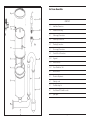
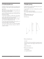
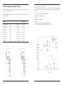
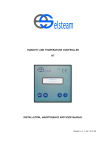
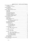
“KT” STEAM HUMIDIFYER
OPERATOR’S MANUAL
USE AND SERVICE
“KT” STEAM HUMIDIFYER
OPERATOR’S MANUAL
USE AND SERVICE
ARTI GRAFICHE M.G.
SARONNO
Air Steam Humidifier
CONTENTS
1.1
Installation Dimensions
1.2
Humidifier Positioning
2.1
Water supply Connections
2.2
Steam Pipe Connections
2.3
Plumbing Connections
3.1
Power supply Connections
3.2
Control Circuit Connections
3.2.1
Hygrostat
3.3.1
Airflow interlock
3.4.1
Room Distribution Unit
4.1
Panel Controls
5.1
Electronic Adjustments
6.1
Starting to work
7.1
Troubleshouting list
8.1
How Elsteam KT Humidifiers works
9.1
Spare parts
-1-
1.1 Installation dimensions
Humidifiers
KT3 single phase
9.1 Spare parts
1.I
Boiler upper part
1.I.M - single phase
1.I.T - triphase
2.1
Stainless steal electrodes
1.I.M - single phase
2.I.T1 - triphase K10
2.I.T2 - triphase K20/K40
2.I.T3 - triphase K60
3.I
4.I
5.I
6.I
7.I
8.I
9.I
10.I
11.I
12.I
13.I
Boiler lower part
Silicon rubber O-ring
Metal ring kit
Rubber curv for syphons
Syphon
Moplen pipe
Rubber manifold
Ispection plug
Infet water electrovalve
Complete power cable
Plastic protection
KT5 biphase
KT10 triphase
KT20 triphase
KT30 triphase
KT40 triphase
KT60 triphase
1.E Electronic card
2.E Power contactor
3.E Trasformer
4.E Power connecting cable
5.E Power fuses holder
2.E.3 single phase
2.E.10 - K10
2.E.20 - K20
2.E.40 - K40
2.E.60 - K60
3.E.3 - single phase
3.E.T - triphase
3.E.T5 - triphase K40/K60
5.E.M - single phase
5.E.T - triphase
6.E Earth pluging
7.E Trasformer fuses hobler
-2-
- 19 -
8.1 How Elsteam humidifier works
1.2 Humidifier positioning
The humidifier washes the boiler and the idraulic system completely, removing
all the limestone, to avoid air pollution coming from water which remained too
long in the boiler.
At the same time, the electronic card tests the entire system: water drain, water
feeder. It points out eventual troubles with lights.
If the water change procedure in the boiler is not correct within 5 minutes, the
machine stops the attempt automatically, switches on the failure led but it starts
the steam production regularly.
The water input for the production is normally enough to start a minimum
production. Then, the humidifier feeds the water in small quantities between long
intervals, untill the production reaches the hygrostat’s demand.
The humidifier drains completely the idraulic system every 2 hours of full production, or in case of salt concentration in the boyler too high.
The water’s drain uses patented double syphon system to avoid the use of
electrovalves and unabling to remove big bit of limestone.
The boiler has also a simple but effective valve which allaws the steam passage
to the output, but it stops the water and gives enough pressure at the boiler to
eject big pieces of limestone.
The Elsteam humidifiers are equipped with a rubber water-pipe, a key to open the
metallic case covers and a steam hose sleeve.
To open the humidifier, loose the screws on the bottom of the cover, lift and
remove the cover.
The cover must be connected to electrical ground.
All the units must be installed (walls, holding brackets, etc.) to work on vertical
position.
The working weight of the units are as follow:
KT3 - KT5 - KT10 - KT20 - KT30: 40 kgs.
KT40 - KT60: 60 kgs.
On the top of the humidifier we have
- steam output
- water feed valve of 3/4”. In the valve the filter has to be cleaned in the regular
maintenance; therefore the rubber supply pipe should be placed for easy
ispections.
- hygrostate cables passing hole.
On the bottom of the humidifier we have
- water discharge piping
- power supply cables passing hole.
- 18 -
-3-
- electrovalve filter
- syphon not cracked or not well closed
- a big piece of limestone in the boiler or in the syphon
- remove the external draining pipes, empty the syphon 7 and test the humidifier.
If the system works, the external draining pipe is not correct (too small or not
vertical enough).
4. During the steam production, the water fills the syphon 7.
check:
- the steam production (if more than supposed, turn clockwise trimmer P3)
- the steam output: syphon sizes, etc.
- the draining plumbing: not opened, etc.
WARNING: AFTER ANY TROUBLES, EMPTY THE VERTICAL SYPHON 7 !!!
2.1 Water supply connections
Feed water must come to the humidifyer from water mains through an intercept
tap of a 1/2” minimum diameter. If more humidifiers are connected to the same
mains, the pipe diameter has to be proportionally increased.
If the water quality is poor, add a secondary mechanical filter to the electrovalve
one of the machine.
The filters must be regularly cleaned - mainly in, the first working period, and with
new plumbing -. To avoid problems, use the Elsteam flexible piping, supplied with
a 3/4” swiwel connection already mounted.
WARNING: Do not feed demineralized water into humidifier!
Supply water need not be potable, but it should not contain physical particles
such as sand, mud, algae, etc. which could interfere with the operation of the
water supply valve. If the water supply system includes a softener composed by
resines cartridges, the stainless steel electrodes in the boyler could be corroded
in a short time (if this happens, the boyler will not be covered by the 2 years
guarantee).
Water pressure must be kept between 2 and 7 bars. The machine works regularly
with feed water having conductivity between, 800 and 8000 (ohm - cm), but it
could also work using water with different caracteristics, giving, however, less
performances. With acid water, you should check for an unusual corrosion, of
the electrodes.
If the feed piping is new, before connecting the humidifier electrovalve, drain the
water for a few minutes, removing all the waste matter.
Intake water temperature must not exceed 50°C.
The electronic controls of the humidifier stop automatically income water in case
of leakage inside the cabinet; however it will be usefull to inspect, every year, all
the idraulic components to avoid any damage.
-4-
- 17 -
7.1 Troubleshooting list
2.2 Steam pipe connections
1. The humidifier is not working: light 1 “machine on” is off.
check:
- line fuses
- transformer fuse
- cover microswitch
- “on” push-button
test:
- transformer
Elsteam humidifiers include a linear stainless steel steam distributor for efficient
humidification of the units inside air and a plastic flange with rubber “o-ring”. The
steam distributor must be installed with the steam holes on the top and far from
possible obstructions of the air ducts (curves, forks, changes in piping section
size, fans, filters, grids, etc.).
The distance between steam distributor and obstruction has to be kept more than
600 mm in the direction of air-flow.
Steam distributors should not be installed close to cooling batteries or humidity
regulation probes and away from the external air input. Put the distributor in the
lowest side of air duct: a minimum distance of 300 mm between the top of the
steam output and the air duct ceiling must be observed to avoid condensation
an the ceiling itself.
Install a condensation tank with an output pipe - 50 cm. away from the steam
distributor - at the bottom of the air duct which is involved in the first steam injection, to avoid damaging of the air duct due to hygrostat or air fan breakdowns.
To recover from steam recondensing in the distributor and in the steam pipes, the
distributor itself must be installed above the steam output of the humidifier. The
steam distributor in the air duct must be slightly tilted (2°); you could automatically
obtain this result mounting the Elsteam flange with the little swelling (see draw)
at the bottom.
Elsteam humidifiers are suitable for connection to air piping with a
pressure of 100 m H20. If the dynamic air pressure is higher, the performance of the Elsteam machine decreases. When the pressure is more than 200
mm H20, the humidifier drains all the water, stops to produce steam and it goes
on alarm mode.
2. The humidifier works: light 1 on, light 4 “washing cycle” is on, but the water
electrovalve is not opened.
check:
- water supply line
- electrovalve filter
- water leakage at the bottom of the machine or between the electrodes on
siphon n. 7
test:
- 12 Vdc on the electrovalve contact
- unscrew the coil of the electrovalve, open the electrovalve and clean the two
small holes in the diaphram.
3. During the washing cycle, the humidifier continues to introduce water without
the light 4 switched off.
check:
- during the washing cycle the water fills completely the syphon for a few seconds.
- if it happens, check:
- the cable between the electrodes and the electronic cards.
- if it still, check:
- 16 -
-5-
Piping between the humidifier and the steam distributor must be istalled to avoid
condensation which leads to gurgling in the room or in the air duct with a loss of
efficiency; if the condensate stops the steam pipe completely, the humidifier drains
all the water from the steam cylinder and it starts working again.
Piping must use the gravity force to drain the recondensed steam towards the
boiler:
- avoid use of pipe size less than 40 mm inside diameter
- avoid sharp bends - curve diameter must not be less than 300 mm
- avoid to siphon the pipe, leading to condensation points
- obtain - if possible - an unifrom minimum gradient (10%) towards the humidifier,
to bring recondensed steam back towards the boiler
- use steam tubing and fittings suitable for temperature up to 120° C at atmosphere pressure and thermally insulated
- the piping has to be supported by brackets mounted every 50 cm or contained
in plastic shaft.
Elsteam humidifiers don't need a separate condensation discharge tube.
If the humidifier steam output position is above the steam distributor in the air
duct, 2 solutions are suitable:
1. If the air duct can be drained from the bottom, install the steam distributor in
the air duct with teh nozzles down and open the end of the steam ditributor
removing the plastic plug: the condenseted steam goes in the drain of the
air duct.
2. If it's difficult to drain the water from the air duct, install the steam distributor
with the nozzles at the top and drain the condenseted steam from the lowest
side of the steam distributor through a small siphon soldered at the bottom of
the distributor itself. (see draw).
-6-
6.1 Start up
Verify:
- the installation of the humidifier is solid and vertical
- the earth terminal of the metallic parts is correctly connected
- the water supply is cleaned, and at a right pressure
- the drain plumbing is well sized and not siphoned
Disconnect the hygrostat, connect the screws 1 & 2 of the humidifier electronic
card to simulate the hygrostat "on", and connect the screw 4 & 5 to simulate
the airflow "on".
Switch on the power supply and the cover microswitch: the light 1 and 2 should
be on. The light 4 lights up and the water starts to fill the boiler washing the
idraulic system completely. If the washing is correct, the light 6 turns
on for a few seconds - the water fills completely the siphon (7) - and
the light 4 switches off. At this time, the light 6 switches off and the
water starts to fill the boiler for the steam production. The electrovalve
stops when the production is at its minimum (0.5 A), then the electrovalve opens for few seconds and with long intervals. The light 3 starts lighting and
the intensity is directly proportional to the production.
Switch-off the humidifier, disconnect the screws 1 & 2 of the electronic card and
connect the hygrostat: verify the correct work of the hygrostat. Disconnect the
screws 4 & 5, connect the airflow interlock and verify; if the airduct fan stops, the
humidifier stops the production.
- 15 -
5.1 Electronic adjustments
2.3 Plumbing connections - Drain connection
All the adjustments described in the following paragraph are carried out using
the trimmers shown in the schedule. The humidifiers are already calibrated in
the factory during the burn-in of the machine. These explanations of electronic
adjustments are meant anly for maintenance following failures or after electronic
spare parts replacements.
P2 and P4 alllow the use of humidistats with output caracteristics different from
those established, as standard, for the humidifiers.
The standard input signal from humidistat to Elsteam humidifiers is 0 V (with no
humidity demand) 10 V (with requested of full humidifier capacity).
If the humidistat gives different output, up to 20 Vdc (pulsed or dc), the humidifier
works without problems, However, if you need better performance, you could
adjust P2 or P4 trimmer.
If the humidifier output is more than 10 Vdc, turn the trimmer P4 counterclockwise,
proportionally to the difference between the actual output and 10 Vdc.
If the humidifier output is less than 10 Vdc, turn the trimmer P4 totally clockwise,
and the trimmer P2 clockwise proportionally to the difference between the actual
output of the hygrostat and 10 Vdc.
To resume the procedure; turn clockwisse the trimmers to increase the output of the hygrostat, or, turn the trimmers counterclockwise to decrease the
output of the hygrostat. In particular, P2 increases the output, P4 decreases
the output.
P3:
This trimmer converts the steam production in a voltage to be compared with
teh demand of the hygrostat.
It's calibrated in the factory. Do not touch!!
P5:
This trimmer adjusts the timing between the water supplies.
The water enters in the boiler in small quantity between large time intervals to
allow the electronic card to control the water quality, ...
P6:
This trimmer is important only when the hygrostat output is not usual. Few kind of
humidistats don't give "0 Volt" when they are meant to stop the steam production
(humidistat asks humidification when the output is between 3 and 10 V, and
dehumidification when the output is between 0 and 3 V).
In this case, set the humidistat to the minimum (20% UR) and turn the trimmer P6
clockwise untill the humidifier stops steam production and then set the humidistat
to the maximum (90%) verifyng that the humidifier lights the led no. 2.
The drain system must be capable of handling ten liters discharge in few seconds,
without opposing counterpressure to the humidifier drain.
The Elsteam humidifier is able to remove the limestone concentrated in the boiler
only if the external drain plumbing is totally free:
- pipe internal diameter not less than 40 mm
- pipe must be vertical, without sharp bends
- the drain of the humidifier must be separate from any other drain. The boiler
is directly connected to the drain system through a syphon: if the drain creates
a vacuum depression, it sucks the water from the humidifier, with an efficiency
loss or a lack of production.
In any case, Elsteam suggests to install a collecting vessel, preferably opened
to the atmosphere, of, al least, 10 liters. If the drain system is made of material
which conducts electricity, it should be earthed.
WARNING: FOR ALL OTHER HYGROSTAT, leave the trimmer P6 fully conterclockwise!!!
- 14 -
-7-
3.1 Power supply connections - Wiring
Elsteam humidifiers are equipped with line-fuses and they must be removed in
case of electrical maintenance.
WARNING: Before switching on the humidifier, connect all metallic parts of the
system to earth!!!
Mod.
KT3 monofase
KT5 bifase
KT10 trifase
KT20 trifase
KT30 trifase
KT40 trifase
KT60 trifase
KT10 trifase
KT20 trifase
Fuses
220V
380V
380V
380V
380V
380V
360V
220V
220V
2 x 6 mmq
2 x 6 mmq
3 x 6 mmq
3 x 10 mmq
3 x 10 mmq
3 x 16 mmq
3 x 25 mmq
3 x 10 mmq
3 x 16 mmq
-8-
2 x 20 A
3 x 20 A
3 x 20 A
3 x 32 A
3 x 32 A
3 x 50 A
3 x 63 A
3 x 32 A
3 x 50 A
Indicator light 6: red "water's leak"
If on, it indicates a leak of water in the machine. In this case, the humidifier
stops the production and it lights the alarm 6 avoiding possible damages in
the room.
During the normal functioning of the machine:
With no demand of hygrostat:
- light 1 on.
With demand of hygrostat:
- light 1 on
- light 2 on, proportionally to the hygrostat demand.
- light 3 on, proportionally to the humidifier production.
- 13 -
4.1 Panel Controls
3.2 Control circuit connections
Elsteam humidifiers are provided with a control front panel containing light
indicators which normally signal the unit's correct functioning and also allows,
in case of failure the possibility to determine the principal causes in the machine
itself and/or related to the connected system.
A complete understanding of the various possible light signals allows, in most
cases, to quickly determine the cause of nay malfunction reducing maintenance
time and costs.
For unknown alarms, please contact Elsteam.
Indicator light 1: green "machine on"
When on, it indicates the controls are supplied. When it turn off, this indicates the
loss of a power supply phase or a mulfunction of the power sypply internal to the
humidifier (see 7.1 Troubleshooting list).
Indicator light 2: green "humidistat's demand"
If on, the humidistat is calling for humidity.
It gets more or less luminous proportionally to the humidity demand of the
hygrostat.
Indicator light 3: green "steam production"
If on, the humidifier produces steam. The light intensity is directly proportional
to the steam production.
Indicator light 4: red "Washing cycle"
If on, it indicates either the water within the humidifier is being flushed, or a
regular cleaning of the electrodes has been performed or, also, because of an
excessive concentration of salt and calcium in the water.
If this indicator light remains on for a long period of time (more than 5 minutes)
and, at the same time, vapor is not generated even with the humidistat calling
for it, the light indicates a mulfunction in a flushing cycle or other anomaly in
the system itself.
After the problem has been soved, it's necessary to turn the system off and on
again to start-up the production.
Indicator light 5: red " steam production too high"
If on, it indicates the humidifier, although measuring a steam production higher
than normal, is not able to wash the boyler and start up the production again.
In this case, the machine stops working and it lights the alarm 5.
Elsteam humidifiers are foreseen to operate in conjuction with practically all kind
of humidistat and to satisfy the major requirements of the installer without the
use of any other optionals.
- 12 -
-9-
3.2.1 Hygrostats
Both humidistats, an-off and modulating type, can be utilized. The proportional
type allows all the possibilities of the humidifier to be taken completely advantage,
obtaining excellent control of the ambient relative humidity without fluctuations
from the desired level. The precision and stability of the humidity depends on
two major parameters:
- precision of the hygrostat used
- inertia of the humidification system
This system inertia is inversely proportional to the capacity of the humidifier which
is related to the needs of the ambient itself. If the humidifier maximum output is
not too low, but it is sized correctly, the precision of the setpoint depends only
from the humidistat.
Elsteam humidifier can be connected directly with:
Hygrostat on-off
This kind of hygrostat has a simple output contact which switches on when the
hygtostat demands humidity.
Wiring connections should be as shown in fig.
At the screw 1 the 12 Vdc voltage - compared with the 0 Volt of screw 3 - is
protected by the fuse F1 - (100 mA).
When the hygrostat demands humidity, the 12 Vdc are supplied to the electronic
card. The contact 3 of the electronic card is unscrew.
Humidistats with continuos or pulsing energized output - on-off
or proportionals -
3.3.1 Airflow interlock
If the humidifier will be installed in a central system, an interlock should be used
between the central fan and the humidifier to stop its operation in case of duct
ceases airflow.
When the system demands humidity, the humidistats gives an output voltage. In
this case, connect the hygrostats to the humidifier electronic card, following fig.
If the humidifier output is more than 20 V, reduce the card input, using P4 (see
5.1 Electronic adjustments)
FAN REMOTE
CONTROL SWITCH
Humidistats with resistive outputs
The humidostats gives a variable resistance related to the humidity.
In this case the connection between humidifier and hygrostat are made with a
three conductor cable. The minimum resistance which should be seen at the input
of the humidifier, is 50 ohms. Wiring connections should be as shown in fig.
- 10 -
The ideal control is composed by two serial contacts - both closed when there is
airflow -; the first, an auxiliary contact of the fan, relays the second, a mechanical
type, which opens when there is an insufficient airflow.
3.4.1 Room distribution unit
To distribute directly the steam in the room, without using the air duct, use the
stainless steel Elsteam room distribution unit.
Observe all the instruction regarding the steam distrubution from the air duct.
The room distribution unit must be installed in the way the steam jet doesn't come
in contact with people, electrical equipments, ceiling, surfaces or lamps.
Avoid to install the steam distributor over machines or material which can be
damaged in case of lack of condensated steam or in case of other failures.
The outlet nozzles should be installed at an height between 180 cm from ground
level and 50 cm from the ceiling.
The steam jet should not reach any object before the steam is completely
reabsorbed (2 metres).
- 11 -