1
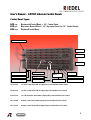
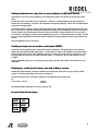
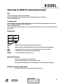
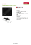
Control Panels (E-Series)
Users’ Manual
interstage
Phistersvej 31, 2900 Hellerup, Danmark
Telefon 3946 0000, fax 3946 0040
www.interstage.dk
- pro audio with a smile
User’s Manual – ARTIST Intercom Control Panels
Control Panel Types:
RCP-xyz
RCP
ECP-xyz
ECP
DCP-xyz
DCP
Rackmount C ontrol P anel = 19”- Control Panel
E xpanison C ontrol P anel = 19”-Expansion Panel for 19”- Control Panels
D esktop C ontrol P anel
Device Description
ECP-1016E
RCP-1012E
RCP-1028E
Gooseneck Microphone
Key LED Display
Headset Connection
Display/Keys
Mic On LED
Level Control
Answer Key
“REPLY“
Loudspeaker
Master Volume Display
Function Keys
Master Volume Control
RCP-1012E
19“/1RU Control Panel with 12 Displays/Keys and individual Level Controls
RCP-1028E
19“/2RU Control Panel with 28 Display/Keys and individual Level Controls
ECP-1016E
19“/1RU Expansion Panel with 16 Displays/Keys and individual Level Controls
DCP-1008E
Desktop Control Panel with 8 Displays/Keys and individual Level Controls
DCP-1016E
Desktop Control Panel with 16 Displays/Keys and individual Level Controls
2
General :
Your ARTIST Control Panel comes equipped with a high quality electret gooseneck microphone. This helps to stifle
undesired noise. Speak in the direction of the microphone with the distance to the microphone as close as possible.
This guarantees optimal understandability and reduces possible feedback.
Adjust the overall volume of your control panel with the Master Volume Control. The volume level is displayed with
a yellow LED in the row of LEDs to the right of the Master Volume control.
In headset mode the color of the master volume display changes from yellow to green. The gooseneck microphone
and the internal loudspeaker are inactive and their functions are switched to the headset connection (4-pin XLR).
You should only use headsets with electret microphones. The power for the headset microphone is delivered by the
control panel. Therefore, be careful that the headset connection is not closed with metal objects.
Display/Keys, Key LED Displays and Level Controls
Your control panel is equipped with Display/Keys. An LED bar is located above every key for the signalization of
the key’s status. Each key uses two contacts which are located under the left and right ends of the keys. These
contacts are only used for special functions and during normal use the key may be pressed on either side.
Additionally, the E-Series control panels have a level control next to each display/key.
The display text shows the destination; press this text if you wish to speak. The destination is programmable
through the Windows configuration software “Director.”
A key’s LED signalization bar shows the current state of the Display/Key. Each key state has a different key
“Marker.”
ARTIST intercom systems have the ability to regulate individual cross points in the matrix. One can set the individual
volume for every destination along with the global volume setting for the control panel. The volume is displayed on
each LED signalization bar in a different color than the rest of the LEDs. The volume LED shows you the actual
volume of incoming audio from this destination.
On a key programmed with a “Call to Panel“ command the volume LED is displayed yellow when the key is
inactive. The rest of the signalization LEDs are also inactive.
“REPLY KEY“
A key with the display <REPLY> answers the previous callers, regardless if they are programmed to another key on
the panel. Every incoming call (except for conferences) are also displayed in the reply key. The key shows the
name of the calling party for approximately 10 seconds after the call (unless specified otherwise in the
programming software). Afterwards the key display returns to “REPLY”. Regardless of what shows in the key’s
display, the last caller is stored so that the pressing the reply key returns the call.
The last four callers are saved in memory. Double clicking on the level control next to the reply key allows you to
scroll through them and select the desired destination by pressing the level control again for longer than 1 second.
3
Types of Calls and their
their Signalization
Description
Call Type
Outgoing Signalization
Incoming Signalization
REPLY
LED Bar
Volume LED
LED Bar
Volume LED
At destination
“Call to Panel”
inactive
--
Off
Yellow
--
--
--
“Call to Panel”
active
Point to Point
Green
Red
Green
Yellow
Yes
“Call to Group”
inactive
--
Off
Off
--
--
--
“Call to Group”
active
Point to
Several Points
Green
Green
Green
Yellow
“Call to
Conference”
inactive
--
Off
Yellow
On Destination Key
--
--
Green
Yellow
Yes
--
“Call to
Conference”
active
Conference
Green
Red
“Listen to
Panel“ inactive
--
Off
Green
--
--
--
“Listen to
Panel“ active
Listen
Yellow
Green
--
--
--
Route audio
inactive
--
Off
Red
--
--
--
Route audio
active
Route
Yellow
Red
On Conference Key
Yes
--The volume control-- knob regulates the
level at the output
Key Modes:
The key modes for each display key can be separately assigned in the configuration software. The three
possibilities are:
Momentary:
The key is active as long as it is pressed.
Latching:
A key press actives the key, the next key press turns it off.
Auto:
If the key is pressed for a short period of time it functions like a “Latching” key
If the key is pressed for a longer period of time it functions like a “Momentary” key
Mic On LED:
This LED blinks red if the control panel microphone is open.
4
Switching between the standard page and the shift page:
The control panels have additional keys available on a shift page. Any expansion panels connected to a control
panel also have a shift page.
Press the function key labeled “SHIFT“ to change to the shift page. A yellow LED next to the “Shift” key means that
the second page is being displayed.
Press the “Shift” key again to return to the standard page.
Headset Mode:
Press the function key labeled “HS” in order to switch the control panel to headset mode. The LED next to the “HS”
key and the master volume display are green when the headset mode is active. The volume of the loudspeaker
and headset are saved in the control panel separately.
The gooseneck microphone and the loudspeaker are inactive and are switched over to the headset connection (4pin male XLR) when the panel is in headset mode. Please use only headsets with electret microphones. The power
for the headset microphone is provided by the panel. Avoid the closing of the headset connection pins with any
metal objects.
Setting individual
individual cross point volumes:
The ARTIST intercom system is equipped with individual level control for each cross point. In addition to setting the
overall volume for a control panel with the master volume control you may also regulate each destination
separately.
Turn the level control next to a display key to the left to reduce the incoming audio from that destination. Turn the
knob to the right to increase the volume. The volume LED correspondingly moves to the left or right. Please note
that the volume change is finer than the change in the LED displays. The LEDs first move after several steps of the
knob.
Resetting all volume levels to the norm:
Double clicking on the master volume control sets all cross point levels back to the norm set in the configuration
software.
Resetting individual volume levels to the norm:
To reset a single cross point level back to the norm, hold down the “NORM” function key while pressing the
display/key of the desired cross point.
Muting an audio source:
To mute an audio source press the level control next to its display key for approximately one second. The volume
display above the key turns red and jumps to the far left. This functions independently of whether or not audio is
active or not at the time of the muting. The call signaling above the keys remains unaffected.
Press the level control again for approximately one second to unmute the cross point. The volume and volume
display will return to the last setting before being muted
An alternative way to unmute the cross point is to simply press the display key. In this case the programmed audio
connection will be created AND the level control will return to the previous level.
Please note that ARTIST differentiates between conferences and group calls. You could, for example, mute all of
the active conferences on your panel and still be reachable through a group call.
5
Adding destinations to a key that are not configured to the panel (Scroll):
This function is only active if is programmed by the configuration software and allowed for specific keys of the
panel.
Double click on the level control next to a display key. If there is a scroll list assigned to the panel but it is not
allowed to scroll on that key, “SCRL N/A” (Not Available) is temporarily displayed. If there is no scroll list assigned
to the panel, nothing happens.
If scrolling is allowed on the key, the key enters the scroll mode (also displayed in the signalization bar above the
key). You may choose between adding panel destinations (including 4 wire destinations), groups and conferences.
Turn the control to scroll between these categories and press the knob for approximately one second to choose
your selection. This brings you into the list of available panels, groups or conferences that may be added. Turn the
knob to scroll through the list and select the desired destination by again pressing the knob for approximately one
second.
The new destination in now on the panel.
Sending an beep tone to another control panel (BEEP):
Press the function key labeled “Beep” along with the desired destination. The signalization bar above the key
displays the beep marker (all LEDs blink yellow). A loud signal tone is hear at the destination panel that changes
between a high and low pitch. If the destination panel has a “call to panel” to the source programmed on a key,
the signalization bar above the key displays the beep marker. A beep tone to groups and conferences is not
available.
Please note that the beep tone is created in the beeped panel. Therefore, this function is not function for 4 wire
destinations.
Displaying a control panel’s name, port and software version:
Pressing the option (OPT) key causes the standard keys to display the option menu as long as the key is being
pressed. Here the specific settings of the panel are displayed.
The port where the panel is connected is displayed, along with the panel‘s display name.
Ex :
Net 1 Node 2 Port 2.3
Camera
Panel 31
The other information displayed is for service purposes only.
Layout of the Function keys:
SHIFT
HS
OPT.
BEEP
NORM
6
Resetting the control panel:
Pressing the function keys “NORM,” “OPT,” and “SHIFT” together resets the control panel.
Pin Assignments of Rear Connectors and Installation of the Control Panel:
Please refer to the ARTIST M Installation Guide for installation instructions as well as the pin assignments for all
connectors on the control panel.
ARTIST E-Series Control Panel Users’ Manual V2 from 29.08.2001. Copyright by RIEDEL.
7
Short
Short Guide for ARTIST M Control Panels (E(E-Series):
Talk:
Press the display/key of the desired destination.
Speak in the direction of the microphone and keep the distance to the mic minimal.
The mic-on LED blinks red.
Answering a call:
Press the “Reply” key or the call key of the person who called (visible in the signalization bar above the
key) and speak in the direction of the microphone.
The mic-on LED blinks red.
Note: Conferences are only signaled on the corresponding conference key and cannot be answered with
the reply key
Function Keys:
SHIFT
HS
OPT.
BEEP
NORM
SHIFT
switches between the standard page and the shift page
HS
switches between headset mode and the gooseneck microphone plus loudspeaker
OPT.
displays panel name, panel number, port and software version of the matrix
BEEP
+ destination key sends beep town to that destination
NORM
+ key returns that key to the norm level
Master Volume Control
Sets the overall volume of the control panel
Press for approximately one second to mute the panel
The volumes of the loudspeaker and the headset are saved in the panel separately
Double click on master volume control
Returns all cross points on the panel back to the norm level
interstage
Phistersvej 31, 2900 Hellerup, Danmark
Telefon 3946 0000, fax 3946 0040
www.interstage.dk
- pro audio with a smile
8