1
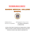
TENDER DOCUMENTS
FOR
CONSTRUCTION OF L 2 & L 3 TRAUMA CENTRES
AND SUPPLY AND INSTALLATION OF MEDICAL
EQUIPMENT IN THE STATE OF BIHAR
Notice no. TCIL/05/ 527/301/2011/ACD/ PACKAGE-2
Dated 01.12.2011
,
(VOLUME- II)- Revised
[SPECIAL CONDITIONS OF CONTRACT (SCC)
&
TECHNICAL SPECIFICATION]
PACKAGE - 2
Telecommunications Consultants India Ltd.
TCIL Bhawan, Greater Kailash-I
New Delhi – 110048
Phone : 91-11-26202020 / Fax No. : 91-11-26242266/26241776
www.tcil-india.com
INDEX
S.NO.
DESCRIPTION
1
SPECIAL CONDITIONS OF CONTRACT(SCC)
2
PARTICULAR SPECIFICATIONS
3
TECHNICAL SPECIFICATIONS
4
LIST OF APPROVED MAKES
Signature & Seal of Contractor
Signature & Seal of TCIL
PAGE
3-6
7
8-150
150-154
2
SPECIAL CONDITIONS OF CONTRACT(SCC)
PART I (GENERAL /CIVIL WORKS)
1.0
INTRODUCTION
The Bihar State Health Society (BSHS), Govt of Bihar, intends to establish 9 Trauma
Centres for Bihar State Health Society in Different District in Bihar. BSHS has
entrusted the work to TCIL Ltd, as Project management consultant. The work broadly
involves construction of Trauma centres building and other facilities like medical
equipments etc.
9 Trauma Centre’s are as underLEVEL II
1.
2.
3.
4.
Distt Hospital (Level – II), Purnia
Darbhanga Medical College(Level – II), Darbhanga
SK Medical College (Level – II), Muzaffarpur
AN Magadh Medical College Hospital (Level – II), Gaya
LEVEL III
5.
6.
7.
8.
9.
Trauma Centre (Level – III) at Civil Hospital, Kishanganj
Civil Hospital (Level – III), Gopalganj
Civil Hospital (Level – III), Jhanjarpur
SH – Sasaram, Distt (Level – III), Rohtas
Civil Hospital (Level – II), Madhepura
The work of 9 Trauma Centres is to be executed in TWO PACKAGES according to
the geographical location in the state.
PACKAGE I
Package I Contains 4 No’s of Trauma Centres in which 1 No Trauma centre (LVL II)
is located in Gaya & Other 3 No Trauma centres (LVL III) are located in Gopalganj,
Sasaram (Rohtas) & Madhepura in Bihar.
PACKAGE II
Package II Contains 5 No’s of Trauma Centres in which 3 Nos Trauma centres (LVL
II) are located in Muzaffarpur , Purnia , Darbhanga & Other 2 No Trauma centres
(LVL III) are located in Kishanganj & Jhanjarpur in Bihar.
2.0
GENERAL
2.1
The work in general shall be carried out as per the latest CPWD / BSR 2011
specifications with upto date correction slips, unless otherwise specified in the
nomenclature of the individual item or as per specifications provided with this tender.
Any item not covered under these specifications shall be carried out as per approved
specifications. In case any item is not covered in any of these documents, the same
shall be carried out as per the latest BIS Code in practice or as per approval of
Engineer in Charge of TCIL.
2.1
Where any portion of special conditions of contract is repugnant to or at variance with
any provision of the with Instructions to Tenderer and General Conditions of contract
and/or the other documents forming part of the contract then unless a different
intention appears the provision of the Special Conditions of Contract shall be deemed
Signature & Seal of Contractor
Signature & Seal of TCIL
3
to override the provisions of the general conditions of contract and / or the other
documents forming part of the contract only to the extent such repugnant/variations in
the special conditions of contract as are not possible of being reconciled with the
provision with Instructions to Tenderer or General Conditions of contract and/or the
other documents forming part of the contract.
2.2
All electrical work shall be carried out as per CPWD specification for Electrical Works
Part-1 Internal Works 2005, Part – II External Work 1995 & BSR 2011. The
installation shall comply with the requirement of India Electricity Rules 1956 as
amended up to date.
3
NATURE OF CONTRACT
3.1
The Contract shall be on percentage rate for all the items for the finished work as per the
Contract Documents.
3.2
The rates quoted by the Contractor shall be deemed to cover for all the minor details /
requirement of construction, which may not have been specifically shown on the
drawings or given in particular specifications, BOQ, but are required as per
established engineering practice.
4
SET OF CONTRACT DOCUMENTS
Tender document shall be read as under:
“The following documents will complete a set of tender documents:
Volume-I
General Conditions of Contract
Instruction to Tenderers
Volume-II
Notice Inviting Tenders
Special Conditions of Contract
Technical Specifications
List of Approved makes
Volume-III
Tender drawings
Volume-IV
Schedule of Rate / Bill of Quantities
5
ACCESS TO SITE
The proposed sites are located in different district/location in Bihar. All the sites are
well connected to the road/rail network. The contractor shall make sure that while
carrying out his responsibilities in connection with this project he will not disrupt traffic
movement along public road or any other approach to the site.
6
DEFINITIONS
Definitions as per General Conditions of Contract (GCC) shall be amended or the
following definitions appended as under
Signature & Seal of Contractor
Signature & Seal of TCIL
4
6.1
The word “Site” in various clauses of General Conditions of Contract (GCC) and other
documents of this Tender shall mean either part or all of “Trauma Centers for Bihar
State Health Society (BSHS) at Bihar”.
6.2
Wherever in General Conditions of Contract, approval of TCIL / Executing Agency is
mentioned, it shall also include the approval from the Owner / Owner’s representative
also.
7
DRAWINGS
7.1
The drawings duly signed by Architect / Consultants are diagrammatic but shall be
followed as closely as actual construction permits. Any deviation made shall be with
prior approval of and in conformity with the directions of the Engineer-in-Charge of
TCIL.
7.2
Architectural drawings shall take precedence over structural drawings and structural
drawings, in turn, shall take precedence over engineering services drawings if any
conflict arises regarding dimensions.
7.3
The contractor shall verify all dimensions at site and bring discrepancies, if any, to the
notice of the Engineer-in-Charge of TCIL before commencing any construction work.
Decision of the Engineer-in-Charge of TCIL will be final and binding on the contractor.
8
SCOPE OF WORK
8.1
The scope of work comprises execution of various items as per BOQ along with
General Conditions of Contract (GCC), Instruction to Tenderers (ITT), Special
Conditions of Contract (SCC), Particular Specifications, and Drawings etc.
8.2
The contractor shall draw up an implementation schedule in consultation with
Engineer-in-Charge of TCIL and BSHS authorities.
8.3
The contractor shall seek and obtain necessary prior permission from BSHS /TCIL
authorities before commencement of work in any area in accordance with the
implementation schedule. Agreement to an implementation schedule does not
provide the contractor permission to commence work in any area without seeking
immediately prior necessary permission to work in that area.
8.4
The contractor shall notify the Engineer-in-Charge of TCIL regarding disruption of
work if and when so happens. Any claim for delay in works on account of such
disruptions or otherwise will not be admissible.
8.5
The contractor shall coordinate with all other sub-contractors or vendors selected by
the client for other works in relation to this job and extend all support to the other
vendors as far as practicable.
8.6
The contractor shall make his own arrangement for storage of materials outside the
site of work. However, if any space is available within the site of work the contractor
shall seek and obtain necessary permission from the BSHS authorities regarding the
same. Nevertheless, security of the material shall be the contractor’s responsibility.
8.7
The contractor shall, at all times, maintain at site one clean set of all drawings issued
to him for reference of the client, consultant or any of their representative.
8.8
Manufacturer’s drawings, catalogues, pamphlets, equipment characteristics data,
performance charts and other documents submitted for approval shall be in four sets.
Each item in each set shall be properly labeled, indicating the specific services for
which material or equipment is to be used, giving reference to the governing section
and clause number and clearly identifying in ink the items and the operating
characteristics. Data of general nature shall not be accepted.
Signature & Seal of Contractor
Signature & Seal of TCIL
5
8.9
The contractor shall maintain a site order book at the site office. All instructions received
from the Engineer-in-Charge of TCIL relating to the work shall be retained in the file.
8.10
The contractor shall establish an effective quality control system at the site and
implement the same to enforce quality control on all items of the work and the project at
all stages.
8.11
The contractor shall take all precautions and preventive measures against fire hazards
at the site and shall assume full responsibility for the same.
8.12
All cutting and drilling of walls or other elements of the building for the proper
entry/installation of inserts, boxes, equipment, etc. shall be carried out using electrically
operated tools only. Manual drilling, cutting, chiseling, etc. shall not be permitted.
8.13
The contractor shall provide luminous painted warning / caution notice boards with
flickering light arrangements around the area of working place on all sides as
applicable where the work is in progress. Any cut-out on floor shall be duly cordoned
off with ribbonned barricades for safety of workers as well as for passersby. Safety to
contractor’s personnel as well as all visitors in and around the area of work shall be
the contractor’s responsibility.
8.14
Before taking up the work of excavation, the contractor shall provide proper
barricading of the trenches as per approved design and as per specifications so as to
avoid access of unauthorized traffic (pedestrians and vehicular) to the place of work.
8.15
The contractor shall not disturb/damage or pull down any hedge, tree, building etc
within the site or his area of operation without the written permission of the Engineerin-Charge of TCIL or concerned local authorities.
8.16
The contractor shall at all the times during the progress of work take all requisite
precautions and use his best endeavors for preventing any riotous or unlawful
behavior by or among the workers and other employees at the work and shall
preserve peace and protection of the inhabitants and the security of property in the
neighborhood of the work.
9
SITE DOCUMENTS
The following site documents shall be maintained by the contractor at site
a)
Copy of contract documents and drawings
b)
Computerized bill format
c)
Site Order Book
d)
Material testing registers/ Quality Inspection Reports
e)
Measurement books on computerized format
f)
Progress bar chart
g)
Sample approval register
h)
Visitors register
i)
Any other detail and specific requirement as deemed necessary
j)
Hindrance Register
k)
Work Diary
l)
Stage passing Register
In case the above are not provided at site within 10 days of placement of LOI, TCIL
shall procure the same at the risk and cost of the contractor and the expenditure so
incurred shall be recovered from the contractors.
10. VIDEO CONFRENCING:
Signature & Seal of Contractor
Signature & Seal of TCIL
6
The contractor shall make provisions of video conferencing at project site. For
monitoring progress by Corporate office, TCIL or other offices as directed by
Engineer-in –charge, TCIL.
PARTICULAR SPECIFICATIONS
CIVIL WORKS
1.
General: The work shall be carried out strictly in accordance with particular
specifications and drawings. The drawings, specifications BOQ etc. shall be taken
complementary and also supplementary to each other and shall form part of this
contract. Any work or material shown on drawings and not specifically included in
BOQ/specification or vice versa shall be executed and deemed to be included in the
scope of work for lump sum rate. However, the steel for reinforcement work shall be
TMT-BARS of Fe-415.
2.
In case there are no specifications for items shown on the drawings or where items
are not exclusively described, the general specifications of CPWD shall be followed
for which nothing extra shall be paid. In case, no details are available even in CPWD
specification, then decision of Engineer-In-charge is final & binding on the contractor.
3.
Scope of works : The scope of work for buildings under this contract includes for full &
final and entire completion of all works including all internal and external services in
all respects described in particular specification Part-I and as shown on drawings
forming part of the contract.
4.
Although all the details of construction have been covered in these documents, any
item or details of construction not specifically covered but obviously implied and
essential to consider Civil works and all internal and external services complete and
functional, shall be deemed to have been covered in the lump sum quoted. The cost
of external development works pertaining to a particular contract shall also be carried
out on a final lump sum price based on the rates quoted for each item. The tenderer
may however, consider a minimum level of specifications conforming to IS code or
National Building Code to cover any missing details.
5.
Sample of Materials: The Contractor shall produce samples of all materials and shall
obtain approval of these in writing from Architect/ Project Engineer before he places
bulk order for the materials for incorporation in the works. The samples must be
produced atleast six week before they are to be incorporated in sample dwelling
units. Materials to be incorporated in the work shall conform to latest relevant ISI. The
items should be ISI marked where manufactured.
6.
Slopes : Adequate slope shall be provided in areas where there is likelihood of
excess of water such as toilets, balconies, verandah, kitchens, terraces, top of
chajjas, window cills, plinth protections etc. though these may not be expressly shown
in drawings.
7.
Curing: Exposed surfaces of all cement works viz. cement concrete, brick work,
flooring, plastering, pointing and the like shall be cured by keeping the surface
adequately and continuously wet as directed by Architect and Project Engineer for at
least seven days where ordinary portland cement has been used. Approved curing
compound may be used in lieu of moist curing with the permission of Architect and
Project Engineer. Such compound shall be applied to all exposed surface of cement
works as soon as possible after the initial setting of cement. This shall be without
extra cost.
Signature & Seal of Contractor
Signature & Seal of TCIL
7
TECHNICAL SPECIFICATIONS
CIVIL WORKS- NON-SCHEDULED ITEMS
1.
CHICKEN WIRE MESH
Chicken Wire Mesh shall be of galvanized mild steel wire cloth conforming to IS 15681970. Wire Cloth shall be regularly woven wire with a number of equally spaced parallel
wire in both warp and weft direction to produce uniformly openings. The wire cloth shall
be properly selvedge by one or more wires in each edge.
2. STAINLESS STEEL RAILING
1.
All Pipes to be Stainless as per SS 304 Grade with tube thickness of 1.6 mm having
tolerance level as per ASTM A554
2. All components in railing including baluster, pipes, caps etc. to be in Gritt Satin finish
3. Balusters
a. The balusters to have a standard height of 856 mm
b. All components used in the baluster to be manufactured using SS 304 grade
material turned and finished on CNC and other automatic Machines.
c. The base plate of the Baluster to be solid Stainless Steel of size 103 mm dia and
6 mm in thickness.
d. All connectors to be fixed to the Baluster using Allen Bolts. The baluster to have
Zero welding except on the bottom plate.
e. Balusters to be fixed using Stainless Steel M8 Fasteners with SS 304 grade
Stainless Steel Caps
f. The Baluster neck to be modular and can be tilted as per the handrail. The neck
plate to be 2 mm thick in Stainless Steel 304.
g. Handrails to be connected to the neck plate using Stainless Steel CSK M5*10
mm Screw only
4. Balusters to be installed with a centre to centre distance of 1 mt. However this
distance can vary as per site conditions
3. POWDER COATED ANODISED ALUMINIUM FRAME
Powder Coated Anodised aluminium frame for windows, ventilators only with one or
more rebates and shutters party fixed type without sash bars and partly with glazed
shutters sliding type without sash bars, aluminium sections weighting 1.30 kg//m for
frames and 0.55 Kg/m for shutters respectively, 10.00 Kg/Sqm (4mm thick) glass
panes including necessary joining cleats glazing clips, rubber packing, anodised
aluminuium snap beading, CP Brass/stainless screws anodised aluminium fitting
such as tower bolts 200/150mm handles 125/100mm for doors windows respectively
and aluminium anodised sliding bolt 300/250mm/ long floor door stopper 150mm over
all length of cover plate all as per schedule of fitting complete all as specified.
4. ACID PROOF TILES
FLOOR APPLICATION
Substrate Preparation
1. The ground should be compacted properly by ramming and applying water on it
as per the standard practice to create a firm base. Ensure that there is no
settlement of base.
2. For Medium Traffic Floor, make 3” thick PCC (plain cement concrete) in 1:4:8.
Laying Method
Signature & Seal of Contractor
Signature & Seal of TCIL
8
a. Prepare base mortar by mixing sand and cement in 1:4 proportions.
b. Lay the mortar on the substrate prepared as mentioned above in required line
and level. It should be noted that in any case the bed mortar thickness should
not be more than 1” thickness.
c. Mark the centerline and fix the tiles on all the corners and center in the required
level. Preferably, start fixing tiles parallel to longer span.
d. Prepare thick cement paste by mixing water & cement. Apply this paste on the
backside of the tile to fix kit.
e. Lay the tiles on this firm base and ram lightly with the help of rubber hammer OR
trowel from top. See that the tile top surface is laid in required line and level with
proper joint gap.
f. Utmost care should be taken while fixing other tiles in terms of matching lines
and keeping exact joint width between tiles. (For maintaining joint width spacers
are recommended of required joint thickness).
g. Fill the joint gaps after 24 hours when the tiles are properly set and cured with
any well-known joint filler. Prepare the consistent paste as per the method
instructed by the joint filler manufacturer. Fill the joint with the help of rubber
trowel. Before grouting all the joints should be free from any dust and impurities.
h. For filling the joints, keep the filler paste on the tiles and fill the gaps by
spreading it in the space between the tiles with the help of rubber trowel in such
a way that the entire area of joint gaps are filled with the joint filler paste. Apply
light pressure of finger in such a way that it creates ‘U’ shape between two
consecutive tiles and works as a small channel to pass water through it.
i. Remove the excess joint filler from the setting time as recommended by the
supplier with the help of rubber trowel.
j. Clean the tile surface with the help of a wet sponge or clean cloth immediately
before setting time of joint filters. Ensure that the joint filler is protected properly
after the mild acid wash as recommended by the joint filler supplier, by
immediately removing the excess acid from the floored area
5.
ANTI STATIC AND ELECTROCONDUCTIVE VINYL FLOORING
Anti-static and electroconductive – Vinyl flooring permanently static conductive pressed
homogeneous vinyl flooring tested as per EN 649. The vinyl flooring should be classified
as per EN 685 as commercial: 43 & Industrial: 43 with a wear layer of 2mm abrasion
thickness loss as per EN 660: Part 1 group ≤0.15mm & volume loss EN660: Part 2
≤4.0mm3. Electrical resistance as per ESD-Approval. SP-method 2472 EN 1081 is R
≤108Ohms & R1 5 X10⁴ ≤ R ≤106Ohms, R2 5 X10⁴ ≤ R ≤106Ohms. Sound reduction as
per EN ISO 717/2 should be Approx. + 4db, Clean room test as per ASTM F51/00
should be Class A. Light fastness as per EN ISO 105-B02 should be ≥ level 6.The slip
resistance as per DIN 51130 EN 13893 should be R97 ≥ 0.3.
Wall Guard - Vinyl Homogeneous
The wear layer covering as per EN 429 should be 1.3mm and surface treatment should
be PU- shield. The total thickness as EN 428 is 1.3mm. The dimensional stability as per
EN 434 is ≤0.40% & Wetroom should be approved by test as per GBR Class VT.
Reaction to fire as per EN 13501-1 is class Ns2 d0, BS 476:part 7is class 1, As/NZS
3837 is Class B, UNI 8457 is class 1 & ASM E84 is class B. The light fastness as per EN
ISO 105-B02 ≥ 6.The chemical resistance as per EN 423 is good resistance. The clean
room test as per ASTM F26/65 is satisfactory & ASTM F51/00 is Class A.
6. ALUMINIUM WORK
A) ALUMINIUM DOORS, WINDOWS AND VENTILATORS:
Aluminium work for doors, windows, ventilators and partitions with extruded built up
standard tubular and other sections of approved make conforming to IS: 733 and IS :
1285, fixed with rawl plugs and screws or with fixing clips, or with expansion hold
fastners including necessary filling up of gaps at junctions, at top, bottom and sides with
Signature & Seal of Contractor
Signature & Seal of TCIL
9
required PVC/neoprene felt etc. Aluminium sections shall be smooth, rust free, straight,
mitered and jointed mechanically wherever required including cleat angle. Aluminium
snap beading for glazing / paneling, C.P. brass / stainless steel screws, all complete as
per architectural drawings and the directions of Engineer-in-charge. (Glazing and
panelling to be paid for separately.
Powder coated aluminium (minimum thickness of powder coating 50 micron).
All Sections of Aluminium work being used in the work will be Powder coated minimum
thickness of powder coating 50 micron
Codes and Standards:
The Codes and standards generally applicable to the work of this section are listed
herein under:
IS: 733 Wrought aluminium and aluminium alloy bars, rods and sections (for general
engineering purpose).
IS: 1285 Wrought aluminium and aluminium alloy extruded round tube and hollow
sections (for general engineering purpose).
IS: 1362 Dimension for screw thread for general purpose.
IS: 1761 Transparent sheet glass for glazing and framing purposes.
IS: 1948 Aluminium doors, window and ventilators.
IS: 1949 Aluminium windows for industrial buildings.
The following clauses are intended to amplify the requirements of the references/
documents listed above and the contractor shall comply with these clauses.
SAMPLES AND SHOP DRAWINGS
All aluminium doors, windows and ventilators shall be furnished by an approved
manufacturer and shall be conforming to IS:1948. Before placing their order, the
contractor shall submit shop drawings and samples for the approval of the Engineer. If
required, the contractor shall also submit the necessary engineering calculations. Shop
drawings shall clearly show all work including mechanical systems, the arrangement of
components, the sequence and details of fabrications, assembly and erection. These
drawings shall also give full size details, all dimensions and thickness anchoring devices
and accessories.
7. FLUSH SHUTTERS FOR DOORS & CUPBOARDS
Flush shutter for doors & cupboards shutters shall be solid core types with block board
core as indicated in Bill of Quantity and shall conform to IS-2202 and ISI marked with
blockboard (conforming to the requirements as per IS-1659 -1969 with frame of 1st class
Hardwood and well matched commercial
3 ply veneering with vertical grains or cross
bands and both faces decorative lamination 1mm thick.
8. FLOAT GLASS
Float Glass Sheet of nominal thickness 4mm (weight not less than 10 kg/sqm) and 5mm
(weight not less than 13.5Kg/Sq.M. Sheet glass shall be flat, transparent and clear as
judged by the naked eye. It may, however, possess a light line when viewed edgewise. It
shall be free from any cracks and other defects. Float Glass make “SAINT GOBAIN” or
other make equivalent to “SAINT GOBAIN” may be used as per approval of Engineer-incharge, TCIL.
9.
ULTRATECH SURFACE TEXTURE FINISH
Signature & Seal of Contractor
Signature & Seal of TCIL
10
10. EARTH FOR FILLING
The earth used for filling shall be free from salts, organic or other deterious matter.
Highly expensive soils like black cotton soil shall not be used, unless so specified. All
clods of earth exceeding 50mm shall be broken or removed. Earth obtained from borrow
pits and surplus earth from excavation, if any, shall be directed by used for filling and
double handling avoided.
Signature & Seal of Contractor
Signature & Seal of TCIL
11
TECHNICAL SPECIFICATIONS
CIVIL WORKS- NON-SCHEDULED ITEMS
2.
CHICKEN WIRE MESH
Chicken Wire Mesh shall be of galvanized mild steel wire cloth conforming to IS 15681970. Wire Cloth shall be regularly woven wire with a number of equally spaced parallel
wire in both warp and weft direction to produce uniformly openings. The wire cloth shall
be properly selvedge by one or more wires in each edge.
2. STAINLESS STEEL RAILING
5.
All Pipes to be Stainless as per SS 304 Grade with tube thickness of 1.6 mm having
tolerance level as per ASTM A554
6. All components in railing including baluster, pipes, caps etc. to be in Gritt Satin finish
7. Balusters
a. The balusters to have a standard height of 856 mm
b. All components used in the baluster to be manufactured using SS 304 grade
material turned and finished on CNC and other automatic Machines.
c. The base plate of the Baluster to be solid Stainless Steel of size 103 mm dia and
6 mm in thickness.
d. All connectors to be fixed to the Baluster using Allen Bolts. The baluster to have
Zero welding except on the bottom plate.
e. Balusters to be fixed using Stainless Steel M8 Fasteners with SS 304 grade
Stainless Steel Caps
f. The Baluster neck to be modular and can be tilted as per the handrail. The neck
plate to be 2 mm thick in Stainless Steel 304.
g. Handrails to be connected to the neck plate using Stainless Steel CSK M5*10
mm Screw only
8. Balusters to be installed with a centre to centre distance of 1 mt. However this
distance can vary as per site conditions
3. POWDER COATED ANODISED ALUMINIUM FRAME
Powder Coated Anodised aluminium frame for windows, ventilators only with one or
more rebates and shutters party fixed type without sash bars and partly with glazed
shutters sliding type without sash bars, aluminium sections weighting 1.30 kg//m for
frames and 0.55 Kg/m for shutters respectively, 10.00 Kg/Sqm (4mm thick) glass
panes including necessary joining cleats glazing clips, rubber packing, anodised
aluminuium snap beading, CP Brass/stainless screws anodised aluminium fitting
such as tower bolts 200/150mm handles 125/100mm for doors windows respectively
and aluminium anodised sliding bolt 300/250mm/ long floor door stopper 150mm over
all length of cover plate all as per schedule of fitting complete all as specified.
4. ACID PROOF TILES
FLOOR APPLICATION
Substrate Preparation
3. The ground should be compacted properly by ramming and applying water on it
as per the standard practice to create a firm base. Ensure that there is no
settlement of base.
4. For Medium Traffic Floor, make 3” thick PCC (plain cement concrete) in 1:4:8.
Laying Method
k. Prepare base mortar by mixing sand and cement in 1:4 proportions.
l. Lay the mortar on the substrate prepared as mentioned above in required line
and level. It should be noted that in any case the bed mortar thickness should
not be more than 1” thickness.
Signature & Seal of Contractor
Signature & Seal of TCIL
12
m. Mark the centerline and fix the tiles on all the corners and center in the required
level. Preferably, start fixing tiles parallel to longer span.
n. Prepare thick cement paste by mixing water & cement. Apply this paste on the
backside of the tile to fix kit.
o. Lay the tiles on this firm base and ram lightly with the help of rubber hammer OR
trowel from top. See that the tile top surface is laid in required line and level with
proper joint gap.
p. Utmost care should be taken while fixing other tiles in terms of matching lines
and keeping exact joint width between tiles. (For maintaining joint width spacers
are recommended of required joint thickness).
q. Fill the joint gaps after 24 hours when the tiles are properly set and cured with
any well-known joint filler. Prepare the consistent paste as per the method
instructed by the joint filler manufacturer. Fill the joint with the help of rubber
trowel. Before grouting all the joints should be free from any dust and impurities.
r. For filling the joints, keep the filler paste on the tiles and fill the gaps by
spreading it in the space between the tiles with the help of rubber trowel in such
a way that the entire area of joint gaps are filled with the joint filler paste. Apply
light pressure of finger in such a way that it creates ‘U’ shape between two
consecutive tiles and works as a small channel to pass water through it.
s. Remove the excess joint filler from the setting time as recommended by the
supplier with the help of rubber trowel.
t. Clean the tile surface with the help of a wet sponge or clean cloth immediately
before setting time of joint filters. Ensure that the joint filler is protected properly
after the mild acid wash as recommended by the joint filler supplier, by
immediately removing the excess acid from the floored area
5.
ANTI STATIC AND ELECTROCONDUCTIVE VINYL FLOORING
Anti-static and electroconductive – Vinyl flooring permanently static conductive pressed
homogeneous vinyl flooring tested as per EN 649. The vinyl flooring should be classified
as per EN 685 as commercial: 43 & Industrial: 43 with a wear layer of 2mm abrasion
thickness loss as per EN 660: Part 1 group ≤0.15mm & volume loss EN660: Part 2
3
≤4.0mm . Electrical resistance as per ESD-Approval. SP-method 2472 EN 1081 is R
8
4
6
4
6
≤10 Ohms & R1 5 X10 ≤ R ≤10 Ohms, R2 5 X10 ≤ R ≤10 Ohms. Sound reduction as
per EN ISO 717/2 should be Approx. + 4db, Clean room test as per ASTM F51/00
should be Class A. Light fastness as per EN ISO 105-B02 should be ≥ level 6.The slip
resistance as per DIN 51130 EN 13893 should be R97 ≥ 0.3.
Wall Guard - Vinyl Homogeneous
The wear layer covering as per EN 429 should be 1.3mm and surface treatment should
be PU- shield. The total thickness as EN 428 is 1.3mm. The dimensional stability as per
EN 434 is ≤0.40% & Wetroom should be approved by test as per GBR Class VT.
Reaction to fire as per EN 13501-1 is class Ns2 d0, BS 476:part 7is class 1, As/NZS
3837 is Class B, UNI 8457 is class 1 & ASM E84 is class B. The light fastness as per EN
ISO 105-B02 ≥ 6.The chemical resistance as per EN 423 is good resistance. The clean
room test as per ASTM F26/65 is satisfactory & ASTM F51/00 is Class A.
6. ALUMINIUM WORK
B) ALUMINIUM DOORS, WINDOWS AND VENTILATORS:
Aluminium work for doors, windows, ventilators and partitions with extruded built up
standard tubular and other sections of approved make conforming to IS: 733 and IS :
1285, fixed with rawl plugs and screws or with fixing clips, or with expansion hold
fastners including necessary filling up of gaps at junctions, at top, bottom and sides with
required PVC/neoprene felt etc. Aluminium sections shall be smooth, rust free, straight,
mitered and jointed mechanically wherever required including cleat angle. Aluminium
snap beading for glazing / paneling, C.P. brass / stainless steel screws, all complete as
Signature & Seal of Contractor
Signature & Seal of TCIL
13
per architectural drawings and the directions of Engineer-in-charge. (Glazing and
panelling to be paid for separately.
Powder coated aluminium (minimum thickness of powder coating 50 micron).
All Sections of Aluminium work being used in the work will be Powder coated minimum
thickness of powder coating 50 micron
Codes and Standards:
The Codes and standards generally applicable to the work of this section are listed
herein under:
IS: 733 Wrought aluminium and aluminium alloy bars, rods and sections (for general
engineering purpose).
IS: 1285 Wrought aluminium and aluminium alloy extruded round tube and hollow
sections (for general engineering purpose).
IS: 1362 Dimension for screw thread for general purpose.
IS: 1761 Transparent sheet glass for glazing and framing purposes.
IS: 1948 Aluminium doors, window and ventilators.
IS: 1949 Aluminium windows for industrial buildings.
The following clauses are intended to amplify the requirements of the references/
documents listed above and the contractor shall comply with these clauses.
SAMPLES AND SHOP DRAWINGS
All aluminium doors, windows and ventilators shall be furnished by an approved
manufacturer and shall be conforming to IS:1948. Before placing their order, the
contractor shall submit shop drawings and samples for the approval of the Engineer. If
required, the contractor shall also submit the necessary engineering calculations. Shop
drawings shall clearly show all work including mechanical systems, the arrangement of
components, the sequence and details of fabrications, assembly and erection. These
drawings shall also give full size details, all dimensions and thickness anchoring devices
and accessories.
7. FLUSH SHUTTERS FOR DOORS & CUPBOARDS
Flush shutter for doors & cupboards shutters shall be solid core types with block board
core as indicated in Bill of Quantity and shall conform to IS-2202 and ISI marked with
st
blockboard (conforming to the requirements as per IS-1659 -1969 with frame of 1 class
Hardwood and well matched commercial
3 ply veneering with vertical grains or cross
bands and both faces decorative lamination 1mm thick.
8. FLOAT GLASS
Float Glass Sheet of nominal thickness 4mm (weight not less than 10 kg/sqm) and 5mm
(weight not less than 13.5Kg/Sq.M. Sheet glass shall be flat, transparent and clear as
judged by the naked eye. It may, however, possess a light line when viewed edgewise. It
shall be free from any cracks and other defects. Float Glass make “SAINT GOBAIN” or
other make equivalent to “SAINT GOBAIN” may be used as per approval of Engineer-incharge, TCIL.
9.
ULTRATECH SURFACE TEXTURE FINISH
Signature & Seal of Contractor
Signature & Seal of TCIL
14
10. EARTH FOR FILLING
The earth used for filling shall be free from salts, organic or other deterious matter.
Highly expensive soils like black cotton soil shall not be used, unless so specified. All
clods of earth exceeding 50mm shall be broken or removed. Earth obtained from borrow
pits and surplus earth from excavation, if any, shall be directed by used for filling and
double handling avoided.
Signature & Seal of Contractor
Signature & Seal of TCIL
15
TECHNICAL SPECIFICATIONS
PLUMBING WORKS- NON-SCHEDULED ITEMS
A)
SANITARY FIXTURES :
1.0
SCOPE OF WORK :
1.1
Work under this section shall consist of furnishing all material and labour
necessary and required to completely install all sanitary fixtures, chromium
plated fittings and accessories as required by the drawings specified
hereinafter and given in the Schedule of Quantities based on DSR items and
as per the specifications given in the CPWD. The items that are given as per
NSR/MR(Non-Scheduled Rate / Market Rate) item shall be provided as per
the technical specification given hereinafter.
1.2
Without restricting to the generality of the foregoing the sanitary fixtures &
C.P. fittings shall include the following:
a)
b)
c)
d)
e)
Sanitary fixtures
Chromium plated fittings
Stainless steel sinks
Accessories e.g toilet paper holders, coat hook, dispenser etc.
Mirror
1.3
Whether specifically mentioned or not all fixtures and appliances shall be
provided with all fixing devices, nuts, bolts, screws, hangers as required.
1.4
All exposed pipes within toilets and near fixtures shall be chromium plated
brass or copper unless otherwise specified.
2.0
GENERAL REQUIREMENTS:
2.1
All materials shall be new and of best quality confirming to specification and
subject to the approval of the Architect/Consultants. Wherever particular
makes are mentioned, the choice of selection shall remain with the
Owner/Architect.
2.2
Sanitary fixtures shall be of the best quality approved by the
Owner/Architect. Wherever particular makes are mentioned, the choice of
selection shall remain with the Owner/Architect.
2.3
All Appliances, fixtures and fittings shall be provided with all such
accessories as are required to complete the item in working condition
whether specifically mentioned or not in the Schedule of Quantities,
specifications, drawings. Accessories shall include proper fixing
arrangement, brackets, nuts, bolts, screws and required connection pieces.
2.4
Fixing screws shall be half round head chromium plated brass screws with
C.P. washers where necessary.
2.5
Porcelain sanitary ware shall be glazed vitreous china of first quality free
from warps, cracks and glazing defects confirming to I.S. 2556.
Signature & Seal of Contractor
Signature & Seal of TCIL
16
2.6
Sinks for pantry or kitchen shall be stainless steel or as specified in the
schedule of quantities.
2.7
Chromium plated fittings shall be cast brass chromium plated of the best
quality approved by the Owner/Architects.
2.8
All Appliances, fittings and fixtures shall be fixed in a neat workmanlike
manner true to level and heights shown on the drawings and in accordance
with the manufacturers recommendations. Care shall be taken to fix all inlet
and outlet pipes at correct positions. Faulty locations shall be made good
and any damage to the finished floor, Filing Plaster, Paint, insulation or
terrace shall be made good by the Contractor at his own cost.
2.9
Sanitary appliances, subject to the type of appliance and specific
requirements, shall be fixed in accordance with the relevant standards and
the following :
a)
Contractor shall, during the entire period of installation and afterwards
protect the appliances by providing suitable cover or any other
protection so as to absolutely prevent any damage to the appliances
until handing over. (The original protective wrapping shall be left in
position for as long as possible).
b)
The appliance shall be fixed in a manner such that it will facilitate
subsequent removal if necessary.
c)
All appliances shall be securely fixed. Manufacturers’ brackets and
fixing methods shall be used wherever possible. Compatible rustproofed fixings shall be used. Fixing shall be done in a manner that
minimizes noise transmission.
d)
Pipe connections shall be made with demountable unions. Pipe work
shall not be fixed in a manner that it supports or partially supports an
appliance.
e)
Appliances shall be fixed so that water falls to the outlet.
f)
Appliances shall be fixed true to level firmly fixed to anchor or supports
provided by the manufacturer and additional anchors or supports where
necessary.
2.10
Sizes of Sanitary fixtures given in the Specifications or in the Schedule of
Quantities are for identification with reference to the catalogues of makes
considered. Dimensions of similar models of other makes may vary within +
10% and the same shall be provided and no claim for extra payment shall be
entertained nor shall any payment be deducted on this account.
3.0
EUROPEAN WATER CLOSET:
a)
WC shall be single or double siphonic wash down type floor/ wall
mounted set, as shown in the drawings, flushed by means of a flushing
cistern.
Signature & Seal of Contractor
Signature & Seal of TCIL
17
b)
Each W.C. set shall be provided with a solid plastic seat of colour given
in the schedule of quantities, rubber buffers and chromium plated
hinges. Plastic seat shall be so fixed that it remains absolutely
stationary in vertical position without falling down on the W.C.
c)
Flush pipe/bend shall be connected to the Water Closet by means of
suitable rubber adapter.
d)
Wall hung/mounted Water Closet if provided shall be supported by C.I.
chair.
4.0
Oval / Counter top WASH HAND BASIN :
4.1.1
Wash basins shall be coloured or white glazed vitreous china of best quality,
size, shape and type specified in the Schedule of Quantities.
4.1.2
Each basin shall be provided with painted MS angle or CI brackets and clips
and the basin securely fixed to wall. Placing of basins over the brackets
without secure fixing shall not be accepted. The MS angle shall be provided
with two coats of red oxide primer and two coats of synthetic enamel paint of
make, brand and colour as approved by the Architect/Consultants.
4.1.3
Each basin shall be provided with 32 mm dia C.P. waste of standard pattern
with pop-up waste or rubber plug and chain as specified in the Schedule of
Quantities, 32 mm dia C.P. brass bottle trap and angle valve with C.P.pipe to
wall and flange as given in the schedule of quantities.
4.1.4
Each basin shall be provided with single hole mixing fitting or as specified in
the Schedule of Quantities.
4.1.5
Basins shall be fixed at proper heights as shown on drawings. If height is not
specified, the rim level shall be 80 cms or as directed by
Architect/Consultants.
5.0
HAND DRIER (IF PROVIDED IN THE DWGS/BOQ):
5.1
The hand drier shall be no touch operating type with solid state time delay to
allow user to keep hand in any position.
5.2
The hand drier shall be fully hygienic, rated for continuous repeat use (CRU).
5.3
The rating of hand drier shall be such that time required to dry a pair of
hands up to wrists is approximately 30 seconds.
5.4
The hand drier shall be of wall mounting type suitable for 230V, single
phase, 50 Hz, AC power supply.
6.0
TOILETS FOR DISABLED (IF PROVIDED IN THE DWGS):
6.1
Where specified in washroom facilities designed to accommodate physically
handicapped, accessories should be provided as directed by the Project
Manager.
Signature & Seal of Contractor
Signature & Seal of TCIL
18
6.2
Stainless steel grab bars of required size suitable for concealed or exposed
mounting and non-slip gripping surface shall be provided in all washrooms to
be used by physically handicapped as directed by the Project Manager.
7.0
ACCESSORIES:
7.1
All C.P. bib taps and Angle valves shall be quarter turn-type washerless
fittings. The angle valve shall be provided with stainless steel mesh filter.
7.2
Contractor shall install all chromium plated stainless steel and powder
coated accessories as shown on the drawings or directed by
Architect/Consultants and given in the Schedule of Quantities.
7.3
All C.P. accessories shall be fixed with C.P. brass half round head screws
and cut washers in wall with rawl plugs or nylon sleeves and shall include
cutting and making good as required or directed by Architect/Consultants.
7.4
Joints/ gaps between all sanitary appliances/fixtures and the floor/ walls shall
be caulked with an approved mildew resistant sealant, having anti-fungal
properties, of colour and shade to match that of the appliance/ fixture and
the floor/ wall to the extent possible.
8.0
TESTING :
All appliances, fixtures and fittings shall be tested before and after
installation. Water seals of all appliances shall be tested. The Contractor
shall block the ends of waste and ventilation pipes and shall conduct an air
test with a pressure of 38mm water gauge for minimum of 3 minutes in
accordance with BS:5572.
B)
SOIL, WASTE, VENT & RAIN WATER PIPES/BASEMENT
DRAINAGE / PLANTER DRAINAGE:
1.0
SCOPE OF WORK :
1.5
1.1
Work under this section shall consist of furnishing all labour,
materials, equipments and appliances necessary and required to completely
install all soil, waste, vent, Rain water pipes, drainage sump riser and fittings
as required by the drawings and given in the Schedule of Quantities based
on DSR items and as per the specifications given in the CPWD. The items
that are given as per NSR/MR(Non-Scheduled Rate / Market Rate) item
shall be provided as per the technical specification given hereinafter.
1.2
Without restricting to the generality of the foregoing, the soil, waste, vent pipe
rain water system shall include the following :a)
Horizontal and Vertical C.I. soil, waste and vent pipes, and fittings, Drip
seal joint, clamps and connection to fixtures.
b)
Floor and Urinal traps, Floor Drain, Cleanout plugs, G.I. inlet fittings and
CP brass/stainless steel grating.
Signature & Seal of Contractor
Signature & Seal of TCIL
19
2.0
2.1
c)
Waste pipe connection from all fixtures e.g wash basins, sinks, urinals,
kitchen equipments and plant room equipment.
d)
uPVC/CI Rain water pipes/CI(LA) Drainage/Sewage Sump Pump Riser.
SOIL, WASTE, VENT & RAIN WATER PIPES AND FITTINGS:
CENTRIFUGAL CAST (SPUN) IRON PIPE
Soil, waste, vent and anti-siphonage pipes, fittings and accessories shall be
centrifugal cast (spun) iron pipes conforming to IS: 3989-1984 or as given in
Schedule of quantities and as per CPWD Specifications.
3.0
TRAPS :
3.1
Floor Trap:
Floor trap shall be cast iron ‘P’ Trap with or without vent horn (deep seal with
an effective seal of 50 mm). In case of Sunken slab in the Toilets, the trap and
waste pipes shall be set in cement concrete blocks of size 300mm x 300mm
and of required depth, firmly supported on the structural floor. The blocks shall
be in 1 :2 :4 mix (1 cement : 2 coarse : 4 stone aggregate 20mm nominal size)
and extended to 40mm below finished floor level. Contractor shall provide all
necessary shuttering and centering for the blocks at no extra cost.). In case of
flat slab instead sunken slab in the Toilets, Contractor shall provide all
sleeves, openings, hangers, inserts during the construction for fixing the floor
traps and etc.
3.2
Urinal Trap:
Urinal traps shall be cast iron P or S traps with or without vent horn and set in
cement concrete block specified under Clause 7.1 Floor Trap without extra
charge.
3.3
Floor Trap Inlet/GI Inlet Fitting:
Traps and connections shall ensure free and silent flow of discharging water.
Where specified, Contractor shall provide a special type cast iron or G.I. inlet
hopper without or with one or two or three inlet sockets to receive the waste
pipe. Joint between G.I. waste pipe and hopper inlet socket shall be Drip seal
joint. Hopper shall be connected to a CI ‘P’ or ‘S’ trap with at least 50mm seal
(hopper and traps shall be paid for separately). Floor trap inlet hoppers and
the traps shall be set in cement concrete blocks/and supports as specified
under clause 7.1 Floor trap above without extra charge.
4.0
CP/S.S. GRATING :
Floor and Urinal Traps, Floor drain shall be provided with 80-125 mm square
or round C.P./stainless steel grating with rim of approved design and shape.
Minimum thickness shall be 4 mm or as specified in the Schedule of
Quantities.
Signature & Seal of Contractor
Signature & Seal of TCIL
20
5.0
CI (LA&B) PIPE AND FITTING:
5.1
Sump Pump discharge Pipe/Rain Water horizontal header/soil waste header
running at Basement ceiling/Rain Water Pipe running underground shall be
centrifugally cast [spun] iron pressure pipe {class LA&B] conforming to IS
1536:2001 or as given in Schedule of quantities and as per CPWD
Specifications.
5.2
Fitting for CI (LA) & B Pipe shall confirm to IS : 1538 – 1967 where possible
junction from branch pipe shall be made by a ‘Y’ Tee.
6.0
CLEAN OUT PLUGS :
6.1
Contractor shall provide cast brass clean out plugs as required. Clean out
plugs shall be threaded and provided with key holes for opening. Clean out
plugs shall be fixed to the pipe by a GI socket and lead caulked joint.
7.0
7.1
WASTE PIPE FROM APPLIANCES :
Waste pipe from appliances e.g. washbasins, sinks and urinals etc. shall be of
Galvanised-iron (GI) heavy duty (class ‘c’) conforming to IS : 1239 Part I or as
given in the Schedule of Quantities/dwgs..
7.2
All pipes shall be fixed in gradient towards the outfalls of drains. Pipes inside a
toilet room shall be in chase unless otherwise shown on drawings. Where
required pipes may be run at ceiling level in suitable gradient and supported
on structural clamps as directed by the Architect/Consultants. Spacing for the
clamps shall be 3000mm for vertical runs and 2400mm for horizontal runs.
7.3
Pipes shall be galvanized steel tubes conforming to IS : 1239 (Heavy Class)
and quality certificates shall be furnished. Pipes shall be provided with all
required malleable fittings conforming to IS : 1879 e.g. tees, couplings, bends,
elbows, unions, reducers, nipples, plugs etc. All GI waste pipes shall be
terminated at the point of connection with the appliance with an outlet of
suitable diameter. Pipes in chase shall be painted with two coats of black
bitumestic paint and exposed pipes with one coat of red oxide primer and two
or more coats of synthetic enamel paint or as given in the Schedule of
Quantities.
8.0
TECHNICAL SPECIFICATION OF WC PAN CONNECTOR:
8.1
The WC pan connector shall be flexible/soft and shall be made of single body
construction with integral fins, made from EVA (Ethgl vingl Acetate). The pan
connector must confirm to BS 5627: 1984. The pan connector must be
supplied with one seal made of TPE (Thermo plastic Elastomeric). The pan
connector must be supplied with factory fitted spring loaded seal guard.
8.2
The connector shall not be allowed to come in contact with mineral oil,
grease, putty or any compound containing mineral oil or grease.
8.3
The pan connector must be stared away from direct sun light and flames.
Signature & Seal of Contractor
Signature & Seal of TCIL
21
9.0
uPVC SOIL / WASTE, RAIN WATER PIPES & FITTINGS:
9.1.1 Rain water pipe shall be uPVC SWR Type A conforming to IS : 13592-1992.
Jointing with
seal ring conforming to IS : 5382 or as given in Schedule of quantities and as
per CPWD Specifications.
9.1.2
Dimension of SWR Pipe Fittings shall be as per DIN 19531 and DIN 19534
and conforms to IS : 14735-1999.
C)
WATER SUPPLY SYSTEM :
1.0
SCOPE OF WORK
1.1
Work under this section consists of furnishing all labour, materials equipment
and appliances necessary and required to completely install for water supply
system (Cold Water Supply + Hot Water Supply) as required by the drawings,
specified hereinafter and given in the Schedule of Quantities or as given in
Schedule of quantities and as per CPWD Specifications.
.
1.2
Without restricting to the generality of the foregoing, the water supply system
shall include the following :a)
Water supply works inside the building etc. including connection to
vertical stack / main line.
b)
c)
d)
Pipe protection and painting.
Connections to all fixtures etc.
Ball valve/butterfly valve/Non Return valve.
2.0
GENERAL REQUIREMENTS :
2.1
All materials shall be new and of the best quality conforming to
specifications. All works executed shall be to the satisfaction of the Project
Manager.
2.2
Pipes and fittings shall be fixed truly vertical, horizontal or in slopes as
required in a neat workmanlike manner.
2.3
Short or long bends shall be used on all main pipe lines as far as possible.
Use of elbows shall be restricted for short connections. As far as possible all
bend shall be formed by means of a hydraulic pipe bending machine for pipe
up to 65 mm dia.
2.4
Pipes shall be laid in a manner as to provide as far as possible easy
accessibility for repair and maintenance and shall not cause obstruction in
shafts, passage etc.
2.5
Valves and other appurtenances shall be so located as to provide easy
accessibility for operations, maintenance and repairs.
Signature & Seal of Contractor
Signature & Seal of TCIL
22
2.6
Pipe shall be securely fixed to wall and ceiling by suitable clamps at intervals
specified.
3.0
CPVC PIPES & FITTINGS
All pipes inside the buildings and where specified, outside the building shall be
CPVC (Chlorinated Polyvinyl Chloride) pipes and fittings of Class specified
and jointing shall be followed as per manufacturer recommendation or as
given in Schedule of quantities and as per CPWD Specifications.
.
GI PIPES, FITTINGS AND VALVES :
4.0
4.1
All pipes where specified, inside/outside the building shall be galvanized steel
tubes conforming to IS: 1239 of Class specified, Installation & Jointing shall be
followed as per manufacturer recommendation or as given in Schedule of
quantities and as per CPWD Specifications.
5.0
BALL VALVES:
All ball valves shall be heavy duty of approved make. Valves shall have
suitable for test pressure of 25 Kg/Sqcm. Ball valves shall conform to the
following specifications.
6.0
Size
Construction
Ends
15 to 50 mm
Bronz body S.S. Working Part
stainless steel balls, spindle, t
eflon seating and gland
packing
Screwed
BUTTERFLY VALVE:
All butterfly valves shall be heavy duty cast steel/iron of approved make. The
valves shall be suitable for 15-20 Kg/Sqcm test pressure & shall conform to
the following specifications Butterfly valve shall be of best quality conforming
to IS: 13095:
6.1.1
Size
Construction
Ends
65 mm and above
Cast steel/iron
Flanged
NON-RETURN VALVES:
All non-return valves shall be provided as shown in the drawings conforming
to relevant Indian Standards and in accordance with the following
specifications.
Signature & Seal of Contractor
Signature & Seal of TCIL
23
Size
Construction
Ends
Upto 50 mm.
Gun metal
Screwed
65 mm and above
cast steel/iron
Flanged
Non-return valves shall be of approved make.
7.0
STERILIZATION OF INSTALLATION:
7.1
The water supply installation shall be sterilized as per standards and as
follows :a)
Tanks and pipes shall be filled and flushed out.
b)
All bib cocks (taps) shall be closed.
c)
Tanks and pipes shall be re-filled while adding a sterilizing admixture
containing 50 parts chlorine to one million parts water.
d)
When the installation is filled all bib cocks (taps) shall be opened
progressively and each allowed to run until the water smells of chlorine.
e)
The installation shall be topped up and more sterilizer added.
f)
The installation shall then be left for three hours and shall then be tested
for residual chlorine, if none is found, the installation shall be drained and
the process repeated.
g)
The installation shall be finally drained and flushed with potable water
before use.
D)
EXTERNAL SEWERAGE & STORM WATER DRAINAGE :
1.0
Scope of Work:
1.1
Without restricting to the generality of the foregoing, the drainage system shall
interalia include:
a) Sewerage/Storm water drainage system including, earth works for
excavation, disposal, backfilling and compaction, pipe lines, manholes,
catch basins and connections to Rain water Harvesting or connected as
indicated by the Architect/Consultants.
b) Overflow from Rain Water Harvesting Pit shall be discharged to existing
Storm Water drain either by gravity or by submersible drainage pump.
c) All pipes, fittings, excavation, concreting, brick masonry Installation &
Jointing shall be followed as per manufacturer recommendation or as
given in Schedule of quantities and as per CPWD Specifications.
Signature & Seal of Contractor
Signature & Seal of TCIL
24
E)
PUMPS & WATER TREATMENT SYSTEM:
1.0
Raw/Domestic Water Supply Pumps
1.1
Water supply pumps shall be suitable for clean filtered water. Pumps shall be
single/multi
stage, monobloc vertical/horizontal, centrifugal pumps with C.I body and
bronze impeller, stainless steel shaft, mechanical seal and coupled to a TEFC
electric motor. Each pump should be operate to a curve required by the
operating conditions.
All parts in contact with water shall be corrosion resistant stainless steel DINNr.1.4401.
Each pump shall be provided with a totally enclosed fan cooled induction
motor of suitable H.P. The motors shall be suitable for 415 volts, 3 phase, 50
cycles A.C. power supply and shall conform to IS 325 operating at 2900 RPM
nominal speed.
Each pumping set shall be provided with 100-mm dia/150 mm dia gunmetal
“Bourdon” type pressure gauge with gunmetal ball valve and connected
piping.
Pump or the whole set shall be stable on rubber vibration eliminating pads
appropriate for each pump as recommended by the manufacturer and
accepted by the Project Managers.
1.2
Headers & Accessories :
The suction and discharge manifolds shall be stainless steel fabricated of
Hot Dipped Galvanized MS. Both manifolds shall be designed to attach to
the system piping at either end of the manifold. Delivery manifold shall
include a pressure gauge. The discharge manifold shall include a socket to
install a pressure transducer with a 4-20mA output. The pressure
transducer shall be factory installed and wired.
Isolation valves shall be installed on the suction and discharge of each
pump. A check valve shall be installed on the discharge of each pump
(optional on the suction side for suction lift applications). Base frame
should also be made of galvanized sheet.
4.0
SUBMERSIBLE PUMPS:
2.1 Submersible pumps for sewage/drainage shall be single stage, single entry
pump. Pump shall be with dynamically balanced impeller connected to a
common shaft to the motor. The vane for sewage pump will be open type,
while for drainage pump, etc. It will be of semi open type.
2.2
Stuffing box shall be provided with mechanical seals.
2.3
Each pump shall be provided with water cooled squirrel cage induction
motor suitable for 415 volts, 3 phase, 50 cycles A.C. power supply.
Signature & Seal of Contractor
Signature & Seal of TCIL
25
3.0
2.4
Each pump shall be provided with liquid level controller for operating the
pump between predetermined levels.
2.5
The pumping set shall be for stationary application and shall be provided
with pump connector in it. The delivery pipe shall be joined to the pump
through a rubber diaphragm, and bend and guide pipe for easy
installation, without disturbing delivery pipe the pump unit shall have a
back pull out design. A rust proof chain shall be provided for each pump.
2.6
Pump shall be provided with all accessories and devices necessary and
required for the pump to make a complete working system.
CHEMICAL DOSING PUMP :
3.1 Chemical dosing system comprising of metering pump, 100 lts. Capacity
HDPE solution tank with level gauge and lid on top.
3.2 Motor driven metering pump with mechanically activated diaphragm with
oil lubricated gear mechanism. The output of the plug should be adjustable
operation from 10-100%. Pump construction shall be corrosion resistant
polypropylene or similar material dosing pump.
3.3 Each pump shall be provided with an injector assembly with suction and
delivery piping complete in all respects.
4.0
LEVEL CONTROLLERS:
4.1 Level controllers shall be electronic low voltage type using required number
of stainless steel type probes, shrouded in PVC sheath or encapsulated in
a stainless steel pipe.
5.0
MULTIGRADE SAND FILTER /ACTIVATED CARBON FILTER :
5.1
Filter shall be designed in accordance with the code of unfired pressure
vessel conforming to I.S. 2825.
5.2
Filter shall be multigrade sand filter/activated carbon filter may be altered to
suite contractor’s own design of the most efficient performance.
5.3
Filters shall be vertical type of required diameter. The shell and dished ends
shall be fabricated from M.S. sheet. Tank suitable to with stand a working
pressure given in Bill of Quantities.
5.4
Each filter shall have at least one pressure tight manhole cover for
inspection and repairs.
Signature & Seal of Contractor
Signature & Seal of TCIL
26
5.5
Each filter shall be provided with screwed or flanged connections for inlet,
outlet individual drain connections and all face piping, diaphragm valves and
all other connections necessary and required.
5.6
Face piping shall be MS / GI. (Heavy Duty).
6.0
PIPE & FLANGE JOINTING
6.1
The piping system and components shall be capable of with standing 150 %
of the working pressure including water hammer effects.
6.2
Flanged joints shall be used for connections to vessels, equipment, flanged
valves and also on suitable straight lengths of pipeline of strategic points to
facilitate erection and subsequent maintenance work.
6.3
Flange thickness shall be as per table below IS : 6392 – 1971. Table – 17/18.
250 mm dia
200 mm dia
150 mm dia
125 mm dia
100 mm dia
80 mm dia
65 mm dia
:
:
:
:
:
:
:
26
24
22
22
20
20
18
mm ;
mm ;
mm ;
mm ;
mm ;
mm ;
mm .
6.4
Pipe Protection :
6.4.1
All pipes above ground and in exposed locations shall be painted with epoxy
paint/anti corrosive paint.
6.5
Welding:
6.5.1
Joints between M.S. Pipes and fittings shall be made with the pipes and
fittings having “V” groove and welded with electrical resistance welding in an
approved manner.
6.5.2
Weld Electrodes shall be of approved make, of grade and type as suitable for
the job and meeting the approval of the engineer.
6.5.3
Joints shall be given a first weld in full width without burrs on the full dia of the
pipe. Welding shall be carried out vertically from the surface to be welded.
Weld fluxes shall not be so plastic such as to fall or drip down.
6.5.4
After application of first coat the weld shall be ground and then another layer
of welding shall take place. The weld shall also be cleaned by grinding.
6.5.5
All pipe cutting shall be by oxy acetylene gas welding only. The cut surface
shall be cleaned and ground by a electric grinder before further welding.
Signature & Seal of Contractor
Signature & Seal of TCIL
27
6.5.6
Pipe cutting or welding in inaccessible areas shall be avoided. Pipes shall not
welded in trenches unless the bottom edge of the pipe does not have clear
space for working with electrode.
6.5.7
For supports, angle pieces shall be cut by oxy acetylene gas and cleaned by
electric grinder. All cutting for bolt inserts shall be by electric drill.
7.0
GI PIPES AND FITTINGS :
7.1
All pipes inside the buildings and where specified, outside the building
shall be galvanized steel tubes conforming to IS: 1239 of Class
specified. When Class is not specified they shall be Heavy Class.
8.0
INSTALLATION AND OPERATING INSTRUCTIONS:
The contractor shall provide detailed operating and installation instructions.
Each set of books shall be prepared especially for the type of equipment
delivered and all operating instructions shall refer only to that particular
equipment. The contractor shall provide a minimum of two bound sets of
installation drawings.
9.0
TECHNICAL DATA SHEET :
Contractor to furnish complete technical data & detail on the format
Contractor furnish the performance curves, dimension detail, installation
detail, pump & motor detail catalogue while submitting the tender.
12.0
ELECTRICAL INSTALLATIONS:
12.1
GENERAL:
This section covers the general requirements for electrical work to be
installed under this specification.
The Contractor shall supply and install all electric wiring, switchgear etc.,
necessary for the complete, safe and satisfactory operation of the plant
covered by the Specification. All electrical wiring and cables shall be
properly tagged to the satisfaction of the Owner.
All equipment provided shall be designed for use in conditions up to 50 oC
ambient air temperature and 100% relative humidity.
All equipment, materials, workmanship and fittings shall comply with the
appropriate Indian Standard Specifications or Code of Practice as listed in
the relevant paragraphs of this Section, or applicable international
standards.
12.2
ELECTRICAL SUPPLY :
The electricity supply shall be 415/240 Volts, 50 Hz, 3 phase, 4 wire. All
equipment shall be designed to operated with a + 10% voltage tolerance
without a loss of rated output.
All cables, equipments shall be so connected as to ensure that the load on
phases are balanced and as per specification given in CPWD-Electrical
works
Signature & Seal of Contractor
Signature & Seal of TCIL
28
ANNEXURE- A : APPLICABLE CODES, STANDARDS AND
PUBLICATIONS
1.0
All material, equipment, supply, erection, testing and commissioning shall
comply with the requirements of Indian Standards and code of practices.
All equipment and material being supplied by the Contractor shall meet the
requirements of IS. Tariff advisory committee’s regulation (fire insurance),
electrical inspectorate and Indian Electricity rules and other
Codes/Publications as given below.
A) General :
SP : 6 (1)
Structural steel sections
IS : 27
Pig lead
IS : 325
Three phase induction motors
IS : 554
Dimensions for pipe threads where pressure tight joints are
required on the threads.
IS : 694
PVC insulated cables for working voltages up to and including
1100 V.
IS : 779
Specification for water meters (domestic type)
IS : 782
Specification for caulking lead
IS : 800
Code of Practice for general construction in steel
IS : 1068
Electroplated coatings of nickel plus chromium and copper plus
nickel plus chromium
IS : 1172
Code of basic requirements for water supply drainage and
sanitation
IS : 1367 (Part- 1)
Technical supply conditions for threaded steel fasteners : Part 1
introduction and general information.
IS : 1367 (Part- 2)
Technical supply conditions for threaded steel fasteners : Part 2
product grades and tolerances.
IS : 1554 (Part- 1)
PVC insulated (heavy duty) electric cables : Part 1 for working
voltages up to and including 1100V.
IS : 1554 (Part- 2)
PVC insulated (heavy duty) electric cables : Part 2 for working
voltages from 3.3 kV up to and including 11 kV.
IS : 1726
Specification for cast iron manhole covers and frames
IS : 1742
Code of practice for building drainage.
IS : 2064
Selection, installation and maintenance of sanitary appliances -
Signature & Seal of Contractor
Signature & Seal of TCIL
29
Code of practice.
IS : 2065
Code of practice for water supply in buildings.
IS : 2104
Specification for water meter boxes (domestic type)
IS : 2373
Specification for water meters (bulk type)
IS : 2379
Colour code for identification of pipe lines
IS : 2527
Code of practice for fixing rainwater gutters and down pipes for
roof drainage.
IS : 2629
Recommended practice for hot dip galvanizing on iron and steel
IS : 3114
Code of practice for laying of cast iron pipes
IS : 4111 (Part 1)
Code of practice for ancillary structures in sewerage system :
Part 1 manholes
IS : 4127
Code of practice for laying glazed stoneware pipes.
IS : 4853
Recommended practice for radiographic inspection of fusion
welded butt joints in steel pipes
IS : 5329
Code of practice for sanitary pipe work above ground for
buildings.
IS : 5455
Cast iron steps for manholes.
IS : 6159
Recommended practice for design and fabrication of material
prior to galvanizing
IS : 7558
Code of practice for domestic hot water installations
IS : 8321
Glossary of terms applicable to plumbing work
IS : 9668
Code of practice for provision and maintenance of water
supplies and fire fighting.
IS : 9842
Preformed fibrous pipe insulation
IS : 9912
Coal tar based coating materials and suitable primers for
protecting iron and steel pipe lines.
IS : 10221
Code of practice for coating and wrapping of underground mild
steel pipelines
IS : 10234
Recommendations for general pipeline welding.
IS : 10446
Glossary of terms relating to water supply and sanitation.
IS : 11149
Rubber Gaskets
IS : 11790
Code of practice for preparation of butt-welding ends for pipes,
Signature & Seal of Contractor
Signature & Seal of TCIL
30
valves, flanges and fittings.
B)
IS : 12183 (Part1)
Code of practice for plumbing in multistoreyed buildings : Part 1
Water supply
IS : 12251
Code of practice for drainage of building basements
IS : 5572
Code of practice for sanitary pipe work
IS : 6700
Specification for design, installation, testing and maintenance of
services supplying water for domestic use within buildings and
their curtilages.
IS : 8301
Code of practice for building drainage
BSEN : 274
Sanitary hardware, waste fittings for basins, bidets and baths.
General technical specifications.
PIPES AND FITTINGS :
IS : 458
Specification for precast concrete pipes (with and without
reinforcement)
IS : 651
Salt glazed stone-ware pipes and fittings
IS : 1239 (Part 1)
Mild steel tubes, tubulars and other wrought steel fittings Part 1
Mild Steel tubes
IS : 1239 (Part 2)
Mild steel tubes, tubulars and other wrought steel fittings : Part
2 Mild steel tubulars and other wrought steel pipe fittings.
IS : 1536
Centrifugally cast (spun) iron pressure pipes for water, gas and
sewage
IS : 1537
Vertically cast iron pressure pipes for water, gas and sewage.
IS : 1538
Cast iron fittings for pressure pipes for water, gas and sewage
IS : 1729
Sand cast iron spigot and socket soil, waste and ventilating
pipes, fittings and accessories.
IS : 1879
Malleable cast iron pipe fittings
IS : 1978
Line pipe
IS : 1979
High test line pipe
IS : 2501
Copper tubes for general engineering purposes
IS : 2643 (Part 1)
Dimensions for pipe threads for fastening purposes : Part 1
Basic profile and dimensions.
IS : 2643 (Part 2)
Dimensions for pipe threads for fastening purposes : Part 2
Tolerances
Signature & Seal of Contractor
Signature & Seal of TCIL
31
C)
D)
IS : 2643 (Part 3)
Dimensions for pipe threads for fastening purposes : Part 3
Limits of sizes.
IS : 3468
Pipe nuts
IS : 3589
Seamless or electrically welded steel pipes for water, gas and
sewage (168.3 mm to 2032 mm outside diameter)
IS : 3989
Centrifugally cast (spun) iron spigot and socket soil, waste and
ventilating pipes, fittings and accessories.
IS : 4346
Specifications for washers for use with fittings for water
services.
IS : 4711
Methods for sampling steel pipes, tubes and fittings
IS : 6392
Steel pipe flanges
IS : 6418
Cast iron and malleable cast iron flanges for general
engineering purposes.
IS : 7181
Specification for horizontally cast iron double flanged pipe for
water, gas and sewage.
VALVES :
IS : 778
Specification for copper alloy gate, globe and check valves for
water works purposes
IS : 780
Specification for sluice valves for water works purposes (50
mm to 300 mm size)
IS : 1703
Specification copper alloy float valves (horizontal plunger type)
for water supply fittings
IS : 2906
Specification for sluice valves for water works purposes (350
mm to 1200 mm size)
IS : 3950
Specification for surface boxes for sluice valves
IS : 5312 (Part 1)
Specification for swing check type reflux (non return) valves :
Part 1 Single door pattern
IS : 5312 (Part 2)
Specification for swing check type reflux (non return) valves :
Part 2 Multi door pattern
IS : 12992 (Part 1)
Safety relief valves, spring loaded : Part 1 – Design
IS : 13095
Butterfly valves for general purposes.
WATER QUALITY TOLERANCE :
IS : 3025
(Part 1 to 44)
Signature & Seal of Contractor
Signature & Seal of TCIL
Method of sampling and test (physical and chemical) for water
and waste water
32
E)
IS : 4764
Tolerance limits for sewage effluents discharged into inland
surface waters
IS : 10500
Drinking water
PUMPS AND VESSELS :
IS : 1520
Specification for horizontal centrifugal pumps for clear cold fresh
water
IS : 2002
Steel plates for pressure vessels for intermediate and high
temperature service including boilers
IS : 2825
Code for unfired pressure vessels
IS : 4682 (Part
1)
Code of practice for lining of vessels and equipment for chemical
processes Part 1 : Rubber lining
IS : 5600
Specification for sewage and drainage pumps
IS : 8034
Specification for submersible pump sets for clear, cold, fresh
water
IS : 8418
Specification for horizontal centrifugal self priming pumps
ANNEXURE – B: PIPE COLOUR CODE
S.No.
Pipe lines
Ground
Colour
1st Colour
Band
2nd Colour
Band
Signal red
1.
Filtered water (all cold
water lines after filter)
Sea green
French blue
2.
Drinking water (normal
temperature)
Sea green
Light orange
3.
Drinking water (chilled
temperature)
Sea green
Light orange
4.
Domestic hot water
Sea green
Light grey
5.
Drainage
6.
LPG
7.
Fire Lines
Black
Canary
yellow
Red
This colour code is as per I.S. 2379-1983.
Signature & Seal of Contractor
Signature & Seal of TCIL
33
Signal red
ANNEXURE – C: LISTING DEVIATIONS OF TENDER
Although deviations are generally not acceptable, but in case it becomes pertinent
as per Manufacturer/Contractor, then he is requested to specifically give the details
of deviations, if any on this sheet and continuation thereof in the below mentioned
format only.
Deviation mentioned at any other place shall not be considered.
S.No.
Item Description
As per Tender
Signature & Seal of Contractor
Signature & Seal of TCIL
Deviation by Tenderer
34
F)
QUALITY ASSURANCE AND QUALITY CONTROL :
1.0
The work shall conform to high standards of design and workmanship,
shall be structurally sound and aesthetically pleasing quality standards
prescribed shall form the backbone for the quality assurance and quality
control system.
2.0
At the site level the Contractor shall arrange the materials, their
stacking/storage in appropriate manner to ensure the quality. Contractor
shall provide equipment and manpower to test continuously the quality of
materials, assemblies etc. as directed by the Engineer-in-Charge. The test
shall be conducted continuously and the result of tests maintained. In
addition the Contractor shall keep appropriate tools and equipment for
checking alignments, levels, slopes and evenness of surface.
3.0
The Engineer- in-Charge shall be free to carry out tests as may be
considered necessary by him at his sole discretion, from time to time, in
addition to those specified in this document. The Contractor shall provide
the samples and labour for collecting the samples nothing extra shall be
payable to the Contractor for samples or for the collection of the samples.
4.0
The test shall be conducted at the site laboratory that may be established
by Engineer-in-Charge or at any other standard Laboratory selected by
Engineer- in-Charge.
5.0
The contractor shall transport the samples to the laboratory for which
nothing extra shall be payable. In the event of Contractor failing to arrange
transportation of the samples in proper time Engineer-in-Charge shall have
them transported and recover two times the actual cost from the
Contractor’s bills.
6.0
Testing charges shall be borne by the Engineer-in-Charge.
7.0
Testing may be witnessed by the Contractor or his authorized
representative. Whether witnessed by the Contractor or not, the test results
shall be binding on the Contractor.
Signature & Seal of Contractor
Signature & Seal of TCIL
35
TECHNICAL SPECIFICATIONS
INTERNAL ELECTRICAL WORKS
A - WIRING
1 - GENERAL
Technical Specifications in this section cover the Internal Wiring Installations comprising of:
Wiring for lights and convenience socket outlets etc. in concealed/surface
conduit/raceways.
Wiring for telephone outlets.
Sub main wiring.
Conduiting for Low Voltage System
2 - STANDARDS AND CODES
Latest upto date Indian Standard (IS) and Code of Practice will apply to the equipment and
the work covered by the scope of this contract. In addition the relevant clauses of the Indian
Electricity Act 1910 and Indian Electricity Rules 1956 as amended upto date shall also apply.
Wherever appropriate Indian Standards are not available, relevant British and / or IEC
Standard shall be applicable.
3 - CONDUITS
3.1 STEEL CONDUITS (If Required) :
These shall be of mild steel 16 gauge upto 32mm and 14 gauge for sizes above 32mm,
electric resistance welded (ERW), electric threaded type having perfectly circular tubing.
Conduits shall be precession welded ERW and shall be fabricated from tested steel strips of
thickness as per IS by high frequency induction weld process. Weld shall be smooth and of
consistent of high quality to ensure crack proof bending. The conduits shall be black enamel
painted inside and outside in its manufactured form. Wherever so specified, the conduit shall
be galvanized. All conduits used in this work shall be ISI embossed.
3.2 MS CONDUITS (If Required) :
The electrical wiring shall be done in recessed MS Conduits, unless mentioned otherwise.
No conduit less than 25mm in diameter shall be used, unless otherwise specifically ask by
Engineer-In-Charge.
3.3 PVC CONDUITS :
Wiring shall be carried out in recessed /surface PVC conduits. The PVC conduits conform to
latest and shall be ISI embossed. The conduits shall be heavy gauge (minimum 2 mm wall
thickness) and the interiors of the conduits shall be free from all obstructions. All joints in
conduits shall be sealed / cemented with approved solvent cement. Damage conduits/fittings
shall not be used. Cut ends of conduits shall not have sharp edges.
3.4 BENDS :
As far as possible, the conduit system shall be so laid out that it shall obviate use of tees,
elbows and sharp bends. No length of conduit shall have more than the equivalent of two
quarter bends from inlet to outlet.
Signature & Seal of Contractor
Signature & Seal of TCIL
36
3.5 CONDUIT ACCESSORIES :
3.5.1 STANDARD ACCESSORIES :
The conduit wiring system shall be complete in all respects, including their accessories.
Bends, couplers etc. shall be solid type in recessed type of works and may be solid or
inspection type as required, in surface type of works. The accessories shall conform in all
respects to the relevant IS. Samples shall be got approved by Engineer-In-Charge before
use.
3.5.2 FABRICATED ACCESSORIES :
Wherever required, outlet/junction boxes of required sizes shall be fabricated from 1.6 mm
thick MS sheets excepting ceiling fan outlet boxes which shall be fabricated from minimum 3
mm thick sheets. The outlet boxes shall be of approved quality, finish and manufacture.
Suitable means of fixing connectors etc., if required, shall be provided in the boxes. The
boxes shall be protected from rust by zinc phosphate primer process. Boxes shall be finished
with minimum 2 coats of enamel paint of approved colour. A screwed brass stud shall be
provided in all boxes as earthing terminal.
4 – WIRES :
Wiring shall be carried out with FRLS insulated 660/1100 volt grade unsheathed single core
wires with electrolytic annealed stranded copper (unless otherwise stated) conductors
conforming to latest IS Code. All wire rolls shall be ISI marked. All wires shall bear
manufacturer's label and shall be brought to site in new and original packages.
Manufacturer's certificate, certifying that wires brought to site are of their manufacture shall be
furnished as required.
5 - COAXIAL CABLES :
The coaxial cables shall be of video band type with operation up to 300 MHz capability. Aging
resistance shall comply with latest code i.e. maximum 5% increase in attenuation at 200 MHz
measured by artificial aging (14 days at 80o C) cables shall meet all exceed following
specifications
Center core Dia
Diaelectric Dia
Dielectric
Outer Conductor Dia
Outer Dia
Bending radius
Impedance
DC Resistance
Screening factor
Attenuation
50 MHz
100 MHz
200 MHz
300 MHz
6
0.8 mm
4.8 mm
PE
5.4 mm
7.0 mm
more than 30 mm
75 ohms
50 ohms/KM
more than 50
6.5
9
13
16
- LAYING OF CONDUITS :
Conduits shall be laid either recessed in walls and ceilings or on surface on walls and
ceilings or partly recessed and partly on surface, as required.
Same rate shall apply for recessed and surface Conduiting in this contract.
Stranded copper conductor insulated wire of size as per schedule of quantities shall be
provided in entire
Conduiting for loop earthing.
Signature & Seal of Contractor
Signature & Seal of TCIL
37
GI wire of suitable size to serve as a fish wire shall be left in all conduit runs to facilitate
drawing of wires after completion of Conduiting.
6.2 SURFACE CONDUITING :
Wherever so desired, conduit shall be laid in surface over finished concrete and/or
plastered brickwork. Suitable spacer saddles of approved make and finish shall be fixed
to the finished structural surface along the conduit route at intervals not exceeding 600
mm. Holes in concrete or brick work for fixing the saddles shall be made neatly by electric
drills using masonry drill bits. Conduits shall be fixed on the saddles by means of good
quality heavy duty MS clamps screwed to the saddles by counter sunk screws. Neat
appearance and good workmanship of surface Conduiting work is of particular
importance. The entire conduit work shall be in absolute line and plumb.
6.3 FIXING OF CONDUIT FITTINGS AND ACCESSORIES :
For concealed Conduiting work, the fittings and accessories shall be completely
embedded in walls/ceilings leaving top surface flush with finished wall/ceiling surface in a
workman like manner.
Loop earthing wire shall be connected to a screwed earth stead inside outlet boxes to
make an effective contact with the metal body.
6.4 PAINTING AND COLOUR CODING OF CONDUITS :
Before laying, conduits shall be painted specially at such places where paint has been
damaged due to vice or wrench grip or any other reason.
If so specified, surface conduits shall be provided with 20 mm wide and 100 mm long
colour coding strips as below
Use
Low voltage
Telephone
Earthing system
Control system lighting
Code colour
Grey
Black
Green
Purple
6.5 PROTECTION OF CONDUITS :
To safeguard against filling up with mortar/plaster etc. all the outlet and switch boxes shall
be provided with temporary covers and plugs which shall be replaced by sheet/plate
covers as required. All screwed and socket joints shall be made fully water tight with
white lead paste.
6.6 CLEANING OF CONDUIT RUNS :
The entire conduit system including outlets and boxes shall be thoroughly cleaned after
completion of erection and before drawing in of cables.
6.7 PROTECTION AGAINST DAMPNESS :
All outlets in conduit system shall be properly drain and ventilated to minimize chances of
condensation/sweating.
6.8 EXPANSION JOINTS :
When crossing through expansion joints in buildings, the conduit sections across the joint
shall be through approved quality heavy duty metal flexible conduits of the same size as
Signature & Seal of Contractor
Signature & Seal of TCIL
38
the rigid conduit. The expansion joint crossing shall be done as approved by Engineer-InCharge.
6.9 LOOP EARTHING :
Loop earthing shall be provided by means of insulated stranded copper conductor wires
of sizes as per Schedule of Quantity laid alongwith wiring inside conduits for all wiring
outlets and sub-mains. Earthing terminals shall be provided inside all switch boxes, outlet
boxes and draw boxes etc.
7 - LAYING AND DRAWING OF WIRES :
7.1 BUNCHING OF WIRES :
Wires carrying current shall be so bunched in conduits that the outgoing and return wires
are drawn into the same conduit. Wires originating from two different phases shall not be
run in the same conduit.
7.2 DRAWING OF WIRES :
The drawing of wires shall be done with due regard to the following precautions:No wire shall be drawn into any conduit, until all work of any nature, that may cause injury
to wire is completed. Burrs in cut conduits shall be smoothen before erection of conduits.
Care shall be taken in pulling the wires so that no damage occurs to the insulation of the
wire. Approved type bushes shall be provided at conduit terminations.
Before the wires are drawn into the conduits, conduits shall be thoroughly cleaned of
moisture, dust, dirt or any other obstruction by forcing compressed air through the
conduits if necessary.
While drawing insulated wires into the conduits, care shall be taken to avoid scratches
and kinks which cause breakage of conductors.
There shall be no sharp bends.
The Contractor shall, after wiring is completed, provide a blank metal/sunmica plate on all
switch / outlet / junction boxes for security and to ensure that wires are not stolen till
switches / outlets etc. are fixed at no extra cost the contractor shall be responsible to
ensure that wires and loop earthing conductors are not broken and stolen. In the event of
the wire been partly / fully stolen, the contractor shall replace the entire wiring alongwith
loop earthing at no extra cost. No joint of any nature whatsoever shall be permitted in
wiring and loop earthing.
7.3 TERMINATION /JOINTING OF WIRES :
Sub-circuit wiring shall be carried out in looping system. Joints shall be made only at
distribution board terminals, switches/buzzers and at ceiling roses/connectors/lamp
holders terminals for lights/fans/socket outlets. No joints shall be made inside conduits or
junction/draw/inspection boxes.
Switches controlling lights, fans or socket outlets shall be connected in the phase wire of
the final sub circuit only. Switches shall never be connected in the neutral wire.
Wiring conductors shall be continuous from outlet to outlet. Joints where unavoidable,
due to any special reason shall be made by approved connectors. Specific prior
permission from Engineer-In-Charge in writing shall be obtained before making such joint.
Signature & Seal of Contractor
Signature & Seal of TCIL
39
Insulation shall be shaved off for a length of 15 mm at the end of wire like sharpening of a
pencil and it shall not be removed by cutting it square or wringing.
Strands of wires shall not be cut for connecting terminals. All strands of wires shall be
twisted round at the end before connection.
Conductors having nominal cross sectional area exceeding 1.5 sq. mm shall always be
provided with crimping sockets. Tinning of the strands shall be done wherever crimping
sockets are not available as per instructions of the Engineer-In-Charge
All wiring shall be labeled with appropriate plastic ferrules for identification.
At all bolted terminals, brass flat washer of large area and approved steel spring washers
shall be used.
Brass nuts and bolts shall be used for all connections.
The pressure applied to tighten terminal screws shall be just adequate, neither too much
nor too less.
Switches controlling lights, fans, socket outlets etc. shall be connected to the phase wire
of circuits only.
Only certified valid license holder wiremen shall be employed to do wiring / jointing work.
7.4 LOAD BALANCING :
The Contractor shall plan the load balancing of circuits in 3 phase installation and get the
same approved by the Engineer-In-Charge before commencement of the work.
7.5 COLOUR CODE OF CONDUCTORS :
Colour code shall be maintained for the entire wiring installation - red, yellow, blue for
three phases, black for neutral and green for earth.
8 - SWITCHES AND FIXTURES :
8.1 SWITCHES :
All 6 and 16 amps switches shall be of the modular enclosed type flush mounted 220
Volt AC of the best quality and standard or as approved by MEP/Architect/Engineer-InCharge. The switch moving and fixed contacts shall be of silver nickel and silver graphite
alloy and contact tips coated with silver. The housing of switches shall be made from high
impact resistant, flame retarding and ultra violet stabilized engineering plastic material.
8.2 FLUSH PLATES :
Switches, receptacles and telephone system outlets in wall shall be provided with molded
cover plates of shape, size and colour approved by the Engineer-In-Charge made from
high impact resistant, flame retarding and ultra violet stabilized engineering plastic
material, and secured to the box with counter sunk round head chromium plated brass
screws. Where two or more switches are installed together, they shall be provided with
one common switch cover plate as described above with notches to accommodate all
switches either in one, two or three rows.
One and two gang switch cover plate, telephone outlet cover plate, 6 and 16 amps
switched/unswitched plates shall have the same shape and size. Three and four gang
switch cover plates shall have the same shape and size. Six and eight gang switch cover
plates shall have the same shape and size. Nine and twelve switch cover plates shall
Signature & Seal of Contractor
Signature & Seal of TCIL
40
have the same shape and size. Wherever five switches, seven switches, ten switches
and eleven switches are to be fixed the next higher size of gang switch cover plate to be
used and extra openings shall be provided with blank-off.
8.3 EXTERNALLY OPERATED SWITCHES :
Externally operated switches, shall be of general purpose type, 250 volts of the proper
size and rating and shall be provided in weather proof enclosures, complete with weather
proof gasketed covers. The MCB’s for all externally operated switches shall be separate
and of proper rating.
8.4 WALL SOCKET OUTLETS :
All 6/16 Amps wall socket outlets unless otherwise mentioned on the drawings shall be
switched, five/six round pin and fitted with automatic linear safety shutters to ensure
safety from prying fingers. Un-switched 6/16 amp wall socket outlets where called for in
the drawings shall be of five/six round pin type. The socket outlets shall be made from
high impact resistant, flame retarding and ultra violet stabilized engineering plastic
material.
The switch and sockets shall be located in the same plate. The plates for 6 amp
switched/un-switched plugs and telephone outlets shall be of the same size and shape.
All the switched and un-switched outlets shall be of the best standard.
An earth wire shall be provided along the cables feeding socket outlets for electrical
appliances. The earth wire shall be connected to the earthing terminal screw inside the
box. The earth terminal of the socket shall be connected to the earth terminal provided
inside the box.
8.5 LIGHTING FIXTURES :
The light fixtures and fittings shall be assembled and installed complete and ready for
service, in accordance with details, drawings, manufacturer's instructions and to the
satisfaction of the Engineer-In-Charge.
Wires brought out from junction boxes shall be encased in GI flexible pipes for connecting
to fixtures concealed in suspended ceiling. The flexible pipes shall be provided with a
check nut at the fixture end.
Pendant fixtures specified with overall lengths are subject to change and shall be
checked with conditions of the job and installed as directed.
All suspended fixtures shall be mounted rigid and fixed in position in accordance with
drawings, instructions and to the approval of the Engineer-In-Charge.
Fixtures shall be suspended true to alignment, plumb, level and capable of resisting all
lateral and vertical forces and shall be fixed as required.
All suspended light fixtures etc. shall be provided with concealed suspension
arrangement in the concrete slab/roof members. It is the duty of the Contractor to make
these provisions at the appropriate stage of construction.
All switch and outlet boxes shall be bonded to earth with insulated stranded copper wire
as specified.
Wires shall be connected to all fixtures through connector blocks.
Signature & Seal of Contractor
Signature & Seal of TCIL
41
Flexible pipes, wherever used, shall be of make and quality approved by the Engineer-InCharge.
9 - MEASUREMENT AND PAYMENT OF WIRING :
Wiring for lights, fans, convenience socket outlets and telephone outlets etc. shall be
measured and paid for on POINT BASIS as itemized schedule of quantities and as
elaborated as below unless otherwise stated.
9.1 PRIMARY AND SECONDARY LIGHT POINT WIRING :
In respect of group control of lights (more than one light controlled by one switch or
MCB), wiring upto the first light in the group shall be measured and paid for as a primary
light point. Wiring for other lights looped in one group for switch controlled as also MCB
controlled lights shall be measured and paid for as secondary light points. Primary light
points for switch controlled lights shall include the cost of control switch whereas primary
light points controlled by MCBs shall not include the switch cost. The cost of MCB
controlling such lights shall not be included in the primary light point rate since the MCB
shall be paid for in the item of DB.
The point wiring basis shall assume average wiring length and average conduiting length
per point based on parameters stipulated in Para 9.2 below. The average wiring length
and average conducting length forming the basis of point wiring payment, shall take the
electrical layouts of the entire project into consideration. Tenderers are advised to seek
clarifications, if they so desire, on this aspect before submitting their tenders. No claim for
extra payment on account of electrical layouts in part or whole of the project requiring
larger average wiring and conduiting length per point, whether specifically shown in
tender drawings or not, shall be entertained after the award of contract.
9.2 PARAMETERS :
Wiring shall be carried out as per following parameters in recessed/ surface conduit
system.
Only looping system of wiring shall be adopted throughout. No joints excepting at wiring
terminals shall be permitted.
All accessories shall be flush type unless otherwise stated.
Lights, fans and 6 amp socket outlets shall be wired as per the item given in the Bill of
Quantities.
Power circuits shall normally have maximum two/one 16 amps socket outlet unless
otherwise stated. Separate circuit shall be run for each Geyser, Window/Split air
conditioners and similar appliances.
Wiring rates shall include painting of conduits and other accessories as required.
Wiring rates shall include cleaning of dust, splashes of colour wash or paint from all
fixtures, fans, and fittings etc. at the time of taking over of the installation.
Wiring rates shall include blanking of outlet boxes to prevent damage/pilferage of wires.
Wiring rates shall include circuit wiring from DB to first control switch & shall be done as
per Bill of Quantities.
Signature & Seal of Contractor
Signature & Seal of TCIL
42
9.3 DEFINITIONS :
9.3.1 WIRING FOR LIGHTS :
PRIMARY LIGHT POINTS :
Wiring for primary light points, as defined in Para 9.1 above, shall commence at the
Distribution Board terminals and shall terminate at the ceiling rose/connector in ceiling
box/lamp holder via the control switch (for switch controlled lights). Rates for primary light
point wiring shall be deemed to be inclusive of the cost of entire material and labour
require for completion of primary light point thus defined including:
Recessed / surface conduting system with all accessories, junction/draw/inspection
boxes, bushes, check nuts etc. complete as required.
Wiring with stranded copper conductor PVC insulated 660/1000 volt grade wires including
terminations etc. complete as required.
Control switch with switch box and cover plate of specified type including fixing screws,
earth terminal etc. complete as required. Cost of this switch is applicable only for switch
controlled points. This cost shall not be applicable for DB controlled points.
Loop earthing with insulated copper wire.
SECONDARY LIGHT POINTS :
Secondary light points, as defined in Para 9.1 above, shall cover the cost of
interconnection wiring between group controlled light fittings and shall be deemed to be
inclusive of the cost of entire materials and labour required for completion of the
secondary light point thus defined including
Recessed / surface conduiting system with all accessories, junction/draw/inspection
boxes, bushes, check nuts etc. complete as required.
Wiring with stranded copper conductor PVC insulated 660/1000 volt grade wires including
terminations etc. complete as required.
Loop earthing with insulated copper wire.
9.3.2 WIRING FOR CEILING FANS :
Wiring for ceiling fan points shall be same as for primary light points.
9.3.3 WIRING FOR EXHAUST FANS :
Wiring for exhaust fan points shall be same as for primary light points and shall in addition
include the cost of providing a 3/5 pin 6 amp socket outlet near the fan alongwith plug top
and a 6 amp control switch at convenient location near the room entry.
9.3.4 WIRING FOR CALL BELL POINTS :
Wiring for call bell points shall be the same as for primary light points. A call bell switch
which include in lieu of the control switch at a convenient location as required.
9.3.5 WIRING FOR TELEPHONE OUTLETS :
Wiring for telephone outlets points shall include the entire wiring and conduiting from the
telephone tag block to the telephone outlet including the telephone outlet complete as
required and as itemized in the Schedule of Quantities
Signature & Seal of Contractor
Signature & Seal of TCIL
43
9.3.6 WIRING FOR TV OUTLETS(if Required) :
Wiring for TV outlet points shall include the entire wiring and conduiting from the Splitter
Box to the TV outlet including the TV outlet complete as required and as itemized in the
Schedule of Quantities.
9.3.7 WIRING FOR CONVENIENCE SOCKET OUTLETS :
3/5 pin 6 amps and 3/6 pin 16 amps single phase switched convenience socket outlets
shall be provided in the building as indicated in the layout drawings.
9.3.8 SUB MAINS WIRING :
Sub mains wiring shall be measured from outer end of the boxes. Extra Loop length shall
be left at each end as required.
10 - ROUTINE AND COMPLETION TESTS :
10.1 INSTALLATION COMPLETION TESTS :
At the completion of the work, the entire installation shall be subject to the following tests:
1.
2.
3.
4.
Wiring continuity test
Insulation resistance test
Earth continuity test
Earth resistivity test
Besides the above, any other test specified by the local authority shall also be carried out.
All tested and calibrated instruments for testing, labour, materials and incidentals
necessary to conduct the above tests shall be provided by the contractor at his own cost.
10.2 WIRING CONTINUITY TEST :
All wiring systems shall be tested for continuity of circuits, short circuits, and earthing after
wiring is completed and before installation is energized.
10.3 INSULATION RESISTANCE TEST :
The insulation resistance shall be measured between earth and the whole system
conductors, or any section thereof with all protection in place and all switches closed and
except in concentric wiring all lamps in position of both poles of the installation otherwise
electrically connected together, a direct current pressure of not less than twice the
working pressure provided that it does not exceed 1100 volts for medium voltage circuits.
Where the supply is derived from AC three phase system, the neutral pole of which is
connected to earth, either direct or through added resistance, pressure shall be deemed
to be that which is maintained between the phase conductor and the neutral. The
insulation resistance measured as above shall not be less than 50 mega ohms divided by
the number of points provided on the circuit the whole installation shall not have an
insulation resistance lower than one mega ohm.
The insulation resistance shall also be measured between all conductors connected to
one phase conductor of the supply and shall be carried out after removing all metallic
connections between he two poles of the installation and in those circumstances the
insulation shall not be less than that specified above.
Signature & Seal of Contractor
Signature & Seal of TCIL
44
The insulation resistance between the frame work of housing of power appliances and all
live parts of each appliance shall not be less than that specified in the relevant Standard
specification or where there is no such specification, shall not be less than half a Mega
ohm or when PVC insulated cables are used for wiring 12.5 Mega ohms divided by the
number of outlets. Where a whole installation is being tested a lower value than that given
by the above formula subject to a minimum of 1 Mega ohms is acceptable.
10.4 TESTING OF EARTH CONTINUITY PATH :
The earth continuity conductor including metal conduits and metallic envelopes of cable in
all cases shall be tested for electric continuity and the electrical resistance of the same
alongwith the earthing lead but excluding any added resistance of earth leakage circuit
breaker measured from the connection with the earth electrode to any point in the earth
continuity conductor in the completed installation shall not exceed one ohm.
10.5 TESTING OF POLARITY OF NON-LINKED SINGLE POLE SWITCHES :
In a two wire installation a test shall be made to verify that all non-linked single pole
switches have been connected to the same conductor throughout, and such conductor
shall be labeled or marked for connection to an outer or phase conductor or to the nonearthed conductor of the supply. In the three of four wire installation, a test shall be made
to verify that every non-linked single pole switch is fitted to one of the outer or phase
conductor of the supply. The entire electrical installation shall be subject to the final
acceptance of the Engineer-In-Charge as well as the local authorities.
10.6 EARTH RESISTIVITY TEST :
Earth resistivity test shall be carried out in accordance with latest IS Code of Practice for
earthing.
10.7 PERFORMANCE :
Should the above tests not comply with the limits and requirements as above the
contractor shall rectify the faults until the required results are obtained. The contractor
shall be responsible for providing the necessary instruments and subsidiary earths for
carrying out the tests. The above tests are to be carried out by the contractor without any
extra charge.
10.8 TESTS AND TEST REPORTS :
The Contractor shall furnish test reports and preliminary drawings for the equipment to
the Engineer-In-Charge for approval before commencing supply of the equipment. The
Contractor should intimate with the tender the equipment intended to be supplied with its
technical particulars. Any test certificates etc., required by the local Inspectors or any
other Authorities would be supplied by the Contractor without any extra charge. All test
reports shall be approved by the Engineer-In-Charge prior to energizing of installation.
B - MEDIUM VOLTAGE DISTRIBUTION BOARDS :
1 – GENERAL :
This section covers specification of DBs.
2 - STANDARDS AND CODES :
The latest and amended upto date Indian Standard Specifications and Codes of Practice
will apply to the equipment and the work covered by the scope of this contract. In addition
the relevant clauses of the Indian Electricity Act 1910 and Indian Electricity Rules 1956 as
Signature & Seal of Contractor
Signature & Seal of TCIL
45
amended upto date shall also apply. Wherever appropriate Indian Standards are not
available, relevant British and/or IEC Standards shall be applicable.
3 - MINIATURE CIRCUIT BREAKERS :
The MCB's shall be of the completely moulded design suitable for operation at 240/415
Volts 50 Hz system.
The MCB's shall have a rupturing capacity of 10 KA at 0.6 p.f.
The MCB's shall have inverse time delayed thermal overload and instantaneous magnetic
short circuit protection. The MCB time current characteristic shall coordinate with XLPE
cable characteristic.
Type test certificates from independent authorities shall be submitted with the tender.
4 - FINAL DISTRIBUTION BOARDS :
Final distribution boards shall be prewired type flush mounting, totally enclosed, Double
door, dust and vermin proof with built in loose wire box and shall comprise of miniature
circuit breakers, earth leakage circuit breakers, neutral link etc as detailed in the schedule
of quantities.
The distribution equipment forming a part of the Distribution Boards shall comply with the
relevant Standards and Codes of the Bureau of Indian.
The board shall be fabricated from 16 gauge CRCA sheet steel and shall have a hinged
lockable spring loaded cover. All cutouts and covers shall be provided with synthetic
rubber gaskets. The entire construction shall give an IP 43 (double door and four tier
arrangement) degree of protection.
The bus-bar shall be of electrical grade copper having a maximum current density of 1.6
ampere per square mm and PVC insulated throughout the length. The minimum spacing
between phases shall be 25 mm and between phase and earth 19 mm
Separate neutral link for each phase shall be provided.
Separate earth link for each phase shall be provided.
All the internal connections shall be with either solid copper PVC insulated or copper
conductor PVC insulated wires of adequate rating.
The equipment shall be mounted on a frame work for easy removal and maintenance.
The sheet steel work shall undergo a rigorous rust proofing process, two coats of filler
oxide primer and final powder coated paint finish.
All the circuits shall have an independent neutral insulated wire, one per circuit, and shall
be numbered and marked as required by the Engineer-In-Charge.
A sample of the completed board is to be got approved by the Engineer-In-Charge before
commencement of supply and erection.
Before commissioning, the distribution boards shall be megger tested for insulation and
earth continuity.
5 - SHEET STEEL TREATMENT AND PAINTING :
Sheet Steel materials used in the construction of these units should have undergone a
rigorous rust proofing process comprising of alkaline degreasing, descaling in dilute
Signature & Seal of Contractor
Signature & Seal of TCIL
46
sulphuric acid and a recognized phosphating process. The steel work shall then receive
two costs of oxide filler primer before final painting. Castings shall be scrupulously
cleaned and fettled before receiving a similar oxide primer coat.
All sheet steel shall after metal treatment be given powder coated finish painted with two
coats of approved shade on the outside and white on the inside. Each coat of paint shall
be properly stoved and the paint thickness shall not be less than 50 microns.
6 - NAME PLATES AND LABELS :
Suitable engraved white on black name plates and identification labels of metal for all
Switch Boards and Circuits shall be provided. These shall indicate the feeder number and
feeder designation.
C - TELEPHONE WIRING SYSTEM :
1 - SCOPE
This section relates to specification for the supply, installation, testing & commissioning of
works included telephone system.
The scope of work included in this section is as follows:
a)
Supply, installation and laying of telephone cables/ wires.
b)
Providing & installing medium duty MS conduit.
c)
Providing & installing G.I./MS moulded boxes including plug in type telephone
outlets.
2 – CONDUITING :
All concealed /surface installation including the conduit run above the false ceiling space
shall be black enameled MS Conduit (as specified in BOQ). The specification for materials & installation shall be same as described in electrical section. All relevant clauses
are applicable for telephone system as well. The conduit for telephone system shall be
installed minimum 20 cm away from the power conduit. Care shall be taken so that no
telephone conduit is run in parallel to Electrical conduit in close proximity. Wherever
telephone conduits cross power conduits, they shall be at right angle, to each other. All
telephone conduits shall be earthed.
3 - TELEPHONE DISTRIBUTION BOARDS (TAG BLOCK) :
Telephone distribution network shall be provided with Main Telephone Distribution board
for building located in Basement level. At each floor, Telephone distribution board tag
block shall be provided in telephone shaft/cupboard. Telephone tag block shall be double
jumpering type.
Tag block shall be mounted in MS box fabricated from 1.63mm thick sheet steel. Box
shall undergo a rigorous metal treatment process i.e. degreasing, pickling, phosphating,
pasivating in deoxalate solution, dry with compressed air in dust free atmosphere facility,
and disconnection module shall be in multiple of 10 pairs. Disconnection unit shall be
mounted on back mounting frame. Protection against over voltage through protection
magazine shall be provided from rear of Disconnection Module.
Telephone distribution box shall have back mounting frame, disconnection module, lock &
key arrangement. Contractor shall also provide one pair of wiring tools, test cord,
Signature & Seal of Contractor
Signature & Seal of TCIL
47
disconnection plug, wiring base. Cost of these items shall deemed to be included in
quoted rates.
Main telephone distribution board shall be provided with protecting magazine with GD
tubes for protection from over voltage. MTDB shall be complete with back mounting
frame. Disconnection module, lock & key arrangement. MTDB box shall be fabricated
from 2mm thick sheet steel.
D - MOULDED CASE CIRCUIT BREAKERS :
1 - GENERAL
Moulded case circuit breakers shall be incorporated in the switch board wherever
specified. MCCB shall conform to IEC:947-II or IS:13947-II in all respects. MCCB shall
be suitable for three phase 415 volts AC. Suitable discrimination shall be provided
between upstream and down stream breakers in the range of 10-20 milli seconds. All
MCCBs will have earth fault module (if specifically asked) and front operated. All four pole
MCCB shall be suitable for three phase four wire system, with the neutral clearly
identified and capable of first make last break feature.
2 - CONSTRUCTION
The MCCB cover and case shall be made of high strength heat-resistant and flame
retardant thermosetting insulating material, operating handle shall be quick make/quick
break. The operating handle shall have suitable `ON' `OFF' and `TRIPPED' mechanical
indicators notable from outside. All MCCBs shall have a common operating handle for
simultaneous operation and tripping of all the three phases. The MCCB should be
suitable for disconnection and isolation with marking on front name plate.
Suitable arc extinguishing device shall be provided for each contact. Tripping unit shall
be thermal-magnetic type provided on each pole and connected by a common trip bar
such that tripping of any one pole operates all three poles to open simultaneously.
Thermal magnetic tripping device shall have IDMT characteristics for sustained over load
and short circuits. All MCCBs above 250 Amps will also have short circuit magnetic
pickup level adjustment.
3 - MCCBs
All MCCBs shall have variable thermal overload releases which can be adjusted at site.
Contact tips shall be made of suitable arc resistant, sintered alloy for long electrical life.
Terminals shall be of liberal design with adequate clearances. All MCCBs of higher
ratings above 250 Amps shall be provided with separate extended arcing contacts.
4 - INTERLOCKING
Moulded case circuit breakers shall be provided with the following interlocking devices for
interlocking the door of a switch board.
a) Handle interlock to prevent unnecessary manipulations of the breaker.
b) Door interlock to prevent the door being opened when the breaker is in ON or OFF
position.
c) Defeat-interlocking device to open the door even if the breaker is in ON position.
Signature & Seal of Contractor
Signature & Seal of TCIL
48
5 - BREAKING CAPACITY
The moulded case circuit breaker shall have a rated service. Short circuit breaking
capacity of not less than 25 KA rms at 415 volts AC. Wherever required, higher breaking
capacity breakers to meet the system short circuit fault shall be used.
6 - ACCESSORIES
All the accessories like shunt, under voltage contact blocks shall be of snap fitting
possible at site.
7 - TESTING
a) Original test certificate of the MCCB shall be furnished.
b) Pre-commissioning tests on the switch board panel incorporating the MCCB shall be
done as per standard specifications.
Signature & Seal of Contractor
Signature & Seal of TCIL
49
TECHNICAL SPECIFICATIONS
EXTERNAL ELECTRICAL WORKS
A - MV CABLES
1 - STANDARDS OF CODES
This chapter covers the specifications for supply and laying of Medium Voltage XLPE
cables.
All equipments, components, materials and entire work shall be carried out in conformity
with applicable and relevant Bureau of Indian Standards and Codes of Practice, as
amended upto date. In addition, relevant clauses of the Indian Electricity Act 1910 and
Indian Electricity Rules 1956 as amended upto date shall also apply. Wherever
appropriate Indian Standards are not available, relevant British and /or IEC Standards
shall be applicable.
2 - CABLES
Medium voltage cables shall be aluminium conductor FR XLPE insulated, PVC sheathed
armoured conforming to latest IS. Cables shall be rated for 1100 Volts.
All Conductor cables shall be as per BOQ.
Conductors shall be insulated with high quality FR XLPE base compound. A common
covering (bedding) shall be applied over the laid up cores by extruded sheath of
unvulcanised compound. Armouring shall be applied below outer sheath of PVC
sheathing. The outer sheath shall bear the manufacturer’s name and trade mark at every
meter length. Cores shall be provided with following colour scheme of PVC insulation.
1 Core
2 Cores
3 Cores
3 ½ /4 Core
:
:
:
:
Red/Black/Yellow/Blue
Red and Black
Red, Yellow and Blue
Red, Yellow, Blue and Black
3 - STORING, HANDLING, LAYING, JOINTING AND TERMINATION
3.1 STORING
All the cables shall be supplied in drums. On receipt of cables at site. It should be
ensured that both ends of the cables are properly sealed to prevent ingress/absorption of
moisture lay the insulation. The cables shall be inspected and stored in drums with
flanges of the cable drum in vertical position. Whenever cable drums have to be moved
over short distances, they should be rolled in the direction of the arrow, marked on the
drum and while removing cables from the drums the drum shall be properly mounted on
jacks or on a cable wheel or any other suitable means making sure the spindle, jack etc.
are strong enough to take the weight of the drum.
3.2 LAYING
Cables shall be laid as per the specifications given below:
Signature & Seal of Contractor
Signature & Seal of TCIL
50
3.3 DUCT SYSTEM
Wherever specified such as road crossing, entry to building or in paved area etc. cables
shall be laid in under ground ducts. The duct system shall consists of a required number
of stone ware pipes, GI, CI or spun reinforced concrete pipe with simplex joints and all the
jointing work shall be done according to the CPWD building specifications or as per the
instructions of the Engineer-In-Charge as the case may be. The size of the pipe shall not
be less than 100mm in diameter for a single cable and shall not be less than 150mm for
more than one cable and so on. The pipe shall be laid directly in ground without making
any special bed but wherever asbestos cement pipes are used, the pipes shall be
encased in concrete of 75mm thick. The ducts shall be properly anchored to prevent any
movement. The top surface of the cable ducts shall not be less than 60 cm. below the
ground level. The ducts shall be laid a gradient of at least 1:300. The duct shall be
provided manholes of adequate size at regular intervals for drawing the cables. The
manhole cover and frame shall be of cast iron and machine finished to ensure a perfect
joint. The manhole covers shall be installed flush with the ground or paved surfaces. The
duct entry to the manholes shall be made leak proof with lead-wool joints. The ducts
shall be properly plugged at the ends to prevent entry of water, rodents, etc. Suitable
duct markers shall be placed along the run of the cable ducts. The duct markers shall at
least be 15 cm. square embedded in concrete, indicating duct. Suitable cable supports
made of angle iron shall be provided in the manholes for supporting the cables. Proper
identification tags shall be provided for each cable in the manholes.
3.4 CABLES IN OUTDOOR TRENCHES:
Cable shall be laid in outdoor trenches wherever called for. The depth of the trenches
shall not be less than 75cm from the final ground level. The width of the trenches shall
not be less than 45 cm. However, where more than one cable is laid, an axial distance of
not less than 15 cm. shall be allowed between the cables. The trenches shall be
excavated in reasonably straight line with vertical side walls and with uniform depth.
Wherever there is a change in direction suitable curvature shall be provided complying
with the requirements. Suitable shoring and propping may be done to avoid caving in of
trench walls. The bottom of the trench shall be level and free from stone brick bats etc.
The trench shall then be provided with a layer of clean, dry sand cushion of not less than
8 cm. in depth.
The cable shall be pulled over rollers in the trench steadily and uniformly without jerks
and strains. The entire cable length shall as far as possible be paved of in one stretch.
However where this is not possible the remainder of the cable may be removed by
"Flaking" i.e. by making one long loop in the reverse direction. After the cable has been
uncoiled and laid into the trench over the rollers, the cable shall be lifted slightly over the
rollers beginning from one end by helpers standing about 10 meters. apart and drawn
straight. The cable should then be taken off the rollers by additional helpers lifting the
cable and then laid in a reasonably straight line.
For short cut runs and sizes upto 50 sq.mm of cables upto 1.1 KV grade any other
suitable method of direct handling and laying can be adopted with the prior approval of
the Engineer-in-charge.
When the cable has been properly straightened, the cores are tested for continuity and
insulation resistance and the cable length then measured. The ends of all cables shall be
sealed immediately. In case of PVC cables suitable moisture seal tape shall be used for
this purpose.
Cable laid in trenches in a single tier formation shall have a covering of clean, dry sand of
not less 17 cms above the base cushion of sand before the protective cover is laid. In the
case of vertical multi tier formation after the first cable has been laid, a sand cushion of 30
cms shall be provided over the initial bed before the second tier is laid. If additional tiers
are formed, each of the subsequent tiers also shall have a sand cushion of 30 cms as
Signature & Seal of Contractor
Signature & Seal of TCIL
51
stated above. The top most cable shall have final sand covering not less than 17 cms
before the protective cover is laid.
Unless otherwise specified, the cables shall be protected by the second class bricks of
not less 20 cms x 10 cms x 10 cms (nominal size) protection covers placed on top of the
sand (bricks to be laid breadth wise) for the full length of the cable. Where more than one
cable is to be laid in the same trench, this protective covering shall cover all the cables
and project at 5 cm. over the sides of the end cables. The trenches shall be taken back
filled with excavated earth free from stones or other sharp edge debris and shall be
rammed and watered, if necessary, in successive layers not exceeding 30 cm, unless
otherwise specified.
3.5 ROUTE MARKER
Cable route marker marked "Cable" shall be provided alongwith the route of the cable and
location of loops. The route markers shall be of tapered concrete slab of 60 x 60cm at
bottom and 50 x 50cm at top having a thickness of 10cm. Cable marker shall be
mounted parallel to and 50cm away from the edge of the trench.
3.6 CABLES IN INDOOR TRENCHES
Cables shall be laid in indoor trenches wherever specified. The trench shall be made of
brick masonry with smooth cement mortar finish with suitable removable covers (i.e.
precasted slabs or chequered plates). The dimensions of the trenches shall be
determined depending upon the maximum number of cables that is expected to be
accommodated and can be conveniently laid. Cables shall be arranged in tier formation
in trenches and if necessary, cables may be fixed with clamps. Suitable clamps, hooks
and saddles shall be used for securing the cables in position. Spacing between the
cables shall not be less than 15 cm centre to centre. Wherever specified, trenches shall
be filled with fine sand and covered with RCC or steel chequered trench covers.
B - EARTHING
1 - GENERAL
This section covers the general arrangement of the earthing, i.e. all non-current carrying
metal parts of the electrical installation shall be earthed as per latest IS code and general
specifications for electrical works (part-1, internal) of CPWD specifications. All metal
conduits, trunkings, cable sheaths, switchgear, distribution boards, meters, light fixtures,
fans and all other metal parts forming part of the work shall be bonded together and
connected by two separate and distinct conductors to earth electrodes. Earthing shall
also be in conformity with the provisions of Rule 32, 61, 62, 67 and 88 of IER 1956. The
earth electrode shall not be situated less than 1.5 meters.
2 - EARTHING SYSTEMS
It shall comprise of earth electrodes, earth strips, earth continuity conductor and all
earthing conductors shall be of high conductivity copper, GI or aluminium and shall be
protected against mechanical damage and corrosion. The size of earth conductors shall
not be less than half that of the largest current carrying conductor. The connection of
earth continuity conductors of earth bus and earth electrodes shall be strong and sound
and shall be rigidly fixed to the walls, cable trenches, cable trays or conduits and cable by
using suitable clamps made of non ferrous metals.
3 - EARTHING ELECTRODES
Earthing electrodes shall be designed as per the requirement of latest IS codes. The
number and size of earth electrodes shall be calculated so that under fault conditions no
Signature & Seal of Contractor
Signature & Seal of TCIL
52
electrode is loaded above its maximum permissible current density. The resistance of
earth electrode shall be as low as possible, the maximum allowable value being one ohm.
Earthing electrodes of either plate type or pipe type may be adopted. The choice of plate
or pipe electrode shall be decided according to the anticipated fault level of the network
and local soil conditions. Generally, plate electrodes shall be used for substations and
large medium voltage network and pipe electrodes for small medium voltage network and
installations.
3.1 LOCATION OF EARTH ELECTRODES
Normally on earth electrode shall not be situated less than 1.5 mtr from any building.
Care shall be taken that the excavation for earth electrode may not effect the column
footings or foundation of the buildings. In such cases electrodes may be further away
from the building.
The location of the earth electrode will be such where the soil has reasonable chance of
remaining moist. As far as possible, entrances, pavements and road ways, are to be
definitely avoided for locating earth electrode.
3.2 WATER ARRANGEMENT
Method of watering arrangement shall comply with CPWD General Specifications.
3.3 PLATE ELECTRODE
Plate electrodes shall be made of GI plate of 6 mm thick and 60x60 cm. size. The plate
shall be buried vertically in ground at depth of not less than 3.5 meters to the top of the
plate, the plate being encased in charcoal to a thickness of 15 cm. all round. It is
preferable to bury the electrode to a depth where sub-soil water is present. Earth leads to
the electrode shall be laid in a GI pipe and connected to the plate electrode with GI bolts,
nuts and washers. A GI pipe of not less than 19 mm Dia shall be placed vertically over
the plate and terminated in a funnel at 5 cm. above ground. The funnel shall be provided
with a wire mesh. The funnel shall be enclosed in masonry chamber of 100 x 50 cm.
dimensions. The chamber shall be provided with CI frame cover of 100 x 50 cm size.
The earth station shall also be provided with a suitable permanent identification label/tag.
Note: If copper plate is used it shall be of 3mm thickness.
3.4 Pipe electrode shall comprise of a 2.5 Meter. long 40 mm Dia GI pipe buried vertically in
a pit of 35 x 35 cm size and filled with alternate layers of charcoal, salt and river sand and
connected at the top to a GI pipe of 19 mm, 1 Meter. long with a funnel at the other end, 5
cm above the ground. The earth lead shall be properly fixed to the pipe electrode with
brass bolts, nuts and washers. The funnel and earth lead connections shall be enclosed
in a masonry chamber of 30 x 30 x 30 cm. dimensions. The chamber shall be provided
with a CI frame and CI cover. Proper permanent identification tag/label shall be provided
for each electrode.
4 - INSTALLATION
All joints shall be reverted and sweated. Joints in the earth bar shall be bolted and the
joints faces tinned. Where the diameter of the bolt for connecting earth bar to apparatus
exceeds one quarter of the width of the earth bar, the connection to the bolt shall be
made with a wider piece of flange of copper jointed to earth bar. These shall be tinned at
the point of connection and special care taken to ensure a permanent low resistance
contact to iron or steel. All steel bolts, nuts, washers, etc shall be cadmium plated. Main
earth bars shall be spaced sufficiently away from the surface to which they are fixed, such
as walls or the side of trenches to allow for easy connections. Copper earth bars shall
not be fixed by ferrous fittings. The earthing shall be suitably protected from mechanical
injury by galvanized iron within ground shall be buried at least 60 cm deep. The earthing
lead shall be securely bolted and soldered to the plate or pipe as the case may be. In the
Signature & Seal of Contractor
Signature & Seal of TCIL
53
case of the plate, the lead shall be connected by means of cable socket with two bolts
and nuts. All washers shall be of the same materials as the plate or pipe. All iron bolts,
nuts and washers shall be galvanized.
4.1 METHOD OF INSTALLATION OF WATERING ARRANGEMENT
In the case of plate earth electrode a watering pipe of 20 mm Dia of medium class GI pipe
shall be provided and attached to the electrode. A funnel with mesh shall be provided on
the top for watering the pit. In case of pipe earth electrode a 40 mm x 20 mm reducer
shall be used for accessing the funnel. The watering funnel attachment shall be housed
in masonary enclosure of not less than 30 cm x 30 cm x 30 cm. A cast iron cover having
locking arrangement shall be suitably embedded in the masonary enclosure.
5 - PRECAUTIONS
Earthing system shall be mechanically robust and the joints shall be capable of retaining
low resistance even after passages of fault currents.
Joints shall be soldered, tinned and double riveted. All the joints shall be mechanically
and electrically continuous and effective. Joints shall be provided against corrosion.
The earthing lead from electrode onwards shall be suitably protected from mechanical
injury by a 15 mm Dia GI pipe in case of wire and by 40 mm Dia medium class GI pipe in
case of strips. Portion of this protection pipe within the ground shall be buried at least 30
cm deep (to be increased to 60 cm in case of road crossing and pavements). The portion
within the building shall be recessed in walls and floor to adequate depth.
6 - TESTING
On the completion of the entire installation, the following tests shall be conducted and no
earth electrode shall have ohmic resistance of more than 2 ohm and in rocky soil not
more than 3 ohms.
a) Earth resistance of electrodes
b) Impedance of earth continuity conductors as per IEE regulations.
c) Effectiveness of earthing as per IEE regulations.
All meters, instruments and labour required for the tests shall be provided by the
contractor. The test results shall be submitted in triplicate to the Architects for approval.
C - MEDIUM VOLTAGE PANELS:
1 - GENERAL
Medium voltage power control centres (generally termed as switchboard panels) shall be
in sheet steel clad cubicle pattern, free floor standing, totally enclosed,
compartmentalized design having multitier arrangement of the incomers and feeders as
per details given in the schedule of quantities. All panels shall conform to the
requirements of the latest addition of IS and shall be suitable for 415 V, 3 phase AC
supply or 230 V single phase AC supply as required.
2 - CONSTRUCTIONAL FEATURES
The Switch Boards shall be totally enclosed, sheet steel cubicle pattern, extensible on
either side, dead front, floor mounting type (wall mounting if specifically asked for in BOQ)
and shall have a bus bar chamber at the top and the cable entry from the bottom. (For
Signature & Seal of Contractor
Signature & Seal of TCIL
54
panel requiring top cable entries if any, refer to BOQ). The cable terminations should be
in side the feeder compartment only.
The Switch Boards shall be completely dust and vermin proof. Synthetic rubber gaskets
between all adjacent units and beneath all covers shall be provided to render the joints
dust and vermin proof to provide a degree of ingress protection of IP 43. All doors and
covers shall also be fully gasketed with synthetic rubber. All the live parts shall be
properly shrouded with FRP sheets.
The Switch Board shall be fabricated with CRCA Sheet Steel of thickness not less than
2.0mm and shall be folded and braced as necessary to provide a rigid support for all
components. The doors and covers shall be constructed from CRCA sheet steel of
thickness not less than 1.6 mm. Joints of any kind in sheet metal shall be seam welded
and all welding slag ground off and welding pits wiped smooth with plumber metal. Base
channel shall be fabricated from ISMC 75 and door shall be provided at the bottom with
arrangement for fixing bolts in the foundation.
All panels and door covers shall be properly fitted and square with the frame. The cutouts
in the panel shall be correctly positioned.
Lifting lugs of adequate strength shall be provided on each transport section of the
panels.
Fixing screws shall enter holes tapped into an adequate thickness of metal or provided
with hank nuts. Self threading screws shall not be used in the construction of the Switch
Boards.
3 - SWITCHBOARD DIMENSIONAL LIMITATIONS
A base channel 75 mm x 5 mm thick shall be provided at the bottom.
The overall height of the Switch Board shall be limited to 2200 mm
The height of the operating handle, push buttons etc shall be restricted between 300 mm
and 1900 mm from finished floor level.
4 - BUS BARS
The bus bars shall be suitable for 4 wire, 415 volts, 50 Hz, system. The main bus bar
shall be made of high conductivity electrolytic grade AL 91E Aluminium. The bus bars
shall have uniform cross section throughout the panel. The bus bars shall be capable of
carrying the rated current at 415 volts continuously. The bus bar will run in a separate
bus bar chamber using bus insulators made of non-deteriorating, vermin proof, non
hygroscopic materials such as epoxy fiber, reinforced polyester or moulding compound
(min. 25mm clearance between phase to phase & phase to neutral bus bars shall be
provided). The interval between the two insulators will be designed after considering the
following:
a)
b)
c)
d)
Strength and safe load rating of the insulator,
The vibrating force generated during a fault,
A Factor of safety of 1.25
A set of insulators at both ends of the bus.
Bus bars shall be sized considering maximum current density of 1 Amps/ cross section
Sq.mm area. The size of the bus bar calculations must be approved by the consultants.
The bus bars shall be designed to withstand a temperature rise of 45oC above the
ambient. To limit the temperature rise in the bus bar chamber a set of louvers can be
provided at strategical places considering the air circulation.
All the bus bars shall be insulated with PVC heat shrinking sleeves throughout (except at
joints) the length of the panel. The electro-galvanized high tensile steel nuts, bolts, plain
Signature & Seal of Contractor
Signature & Seal of TCIL
55
or spring washers of suitable size will be used in connecting the various sections of the
bus bars.
5 - SWITCH BOARD INTERCONNECTIONS
All connections between the bus bars/Breakers terminations shall be through solid
Aluminium strips of adequate size to carry full rated current which shall be PVC/fiber
glass insulated.
For switch unit ratings upto 63A PVC insulated copper conductor wires of adequate size
to carry full load current can be used. The terminations of all such interconnections shall
be properly crimped.
6 - CABLE TERMINATIONS
Knockout holes of appropriate size and number shall be provided in the Switch Board in
conformity with the location of incoming and outgoing conduits/cables. All cable entries
shall be from bottom until & unless specifically asked for in the BOQ.
The cable terminations of the circuit breakers shall be brought out to terminal cable
sockets suitably located in the panel.
All outgoing links for FSU\MCB feeders shall be in the feeder compartment only.
The Switch Boards shall be complete with tinned brass cable sockets, tinned brass
compression glands, gland plates, supporting clamps and brackets etc for termination of
1100 volt grade aluminium conductor PVC cables.
7 - EARTHING
The panels shall be provided with an aluminium earth bus of suitable size running through
out the length of the switchboard. Suitable earthling eyes/bolts (at min. two points) shall
be provided on the main earthing bus to connect the same to the earth grid at the site.
Sufficient number of star washers shall be provided at the joints to achieve earth
continuity between the panels and the sheet metal parts.
8 - INTERLOCKING
The panels shall be provided with the following interlocking arrangement.
The door of the switch-fuse compartments is so interlocked with the switch drive or
handle that the door can be opened only if the switch is in `OFF' position. De-interlocking
arrangement shall also be provided for occasional inspection.
It shall not be possible for the breaker to be withdrawn when in `ON' position.
It shall not be possible for the breakers to be switched on unless it is either in fully
inserted positions or for testing purposes in fully isolated position.
The breaker shall be capable of being raked in to `testing' `isolated' and `maintenance'
positions and kept locked in any of these position.
A safety latch to ensure that the movement of the breaker as it is withdrawn, is checked
before it is completely out of the cubicle shall be provided.
9 - WIRING
All wiring for relays and meters shall be with PVC insulated copper conductor wires. The
wiring shall be coded and labeled with approved ferrules for identification. The minimum
size of copper conductor control wires shall be 1.5 sq.mm except for the circuits related to
Signature & Seal of Contractor
Signature & Seal of TCIL
56
current transformers or circuits with current carrying capacity more than 5 Amps (for
which min. 2.5 Sq.mm copper conductor wires shall be used).
10 - SHEET STEEL TREATMENT AND PAINTING
Sheet Steel materials used in the construction of these units should have undergone a
rigorous rust proofing process comprising of alkaline degreasing, descaling in dilute
sulfuric acid and a recognized phosphating process. The steel work shall then receive two
coats of oxide primer before final painting. Castings shall be scrupulously cleaned and
fettled before receiving a similar oxide primer coat.
All sheet steel shall after metal treatment shall be powder coated with shade RAL 7032
(Siemens Gray) on the outside of the panel and mounting plates shall be of orange
shade. Each coat of paint shall be properly stoved and the paint thickness shall not be
less than 50 microns (shade of paint may be changed if the Engineer In charge so
desires).
11 - NAME PLATES AND LABELS
Suitable engraved white on black name plates and identification labels of metal for all
Switch Boards and Circuits shall be provided. These shall indicate the feeder number and
feeder designation.
12 - INSTALLATION
Installation shall be done by erection Contractor.
13 - TESTING AND COMMISSIONING
Copies of type tests and routine test as per relevant specification, carried out at
manufacturer’s work shall be submitted to the ENGINEER IN CHARGE as required.
Wiring and connections including earthing shall be checked for continuity and tightness.
Insulation shall be measured with a 500 V megger and insulation resistance shall not be
less than 100 Mega ohms
Interlocking operation to be checked as per requirement.
Tests shall be performed in presence of authorized representative of the ENGINEER IN
CHARGE for which the contractor shall give due prior notice.
14 - HIGH VOLTAGE TEST
A high voltage test with 2.5 KV for one minute shall be applied between the poles and
earth. Test shall be carried out on each pole in turn with the remaining poles earthed, all
units raked in position and the breakers closed. Original test certificate shall be submitted
along with panel.
15 - PRE-COMMISSION TESTS:
Panels shall be commissioned only after the successful completion of the following tests.
The tests shall be carried in the presence of Architect's/Consultant's or their
representatives.
All main and auxiliary bus bar connections shall be checked and tightened.
All wiring termination and bus bar joints shall be checked and tightened.
Wiring shall be checked to ensure that it is according to the drawing.
Signature & Seal of Contractor
Signature & Seal of TCIL
57
All wiring shall be tested for insulation resistance by 1000 volts Meggar.
Phase rotation tests shall be conducted
All relays and protective devices shall be tested for correctness of settings and
operation by
introducing a current generator and an ammeter in the circuit.
16 - CLIMATIC CONDITIONS
The panels & switch gear components shall be suitable for following climatic conditions:
Maximum
DBT
RH
Minimum
O
O
45 C
90%
3 C
20%
17 - HEATING ARRANGEMENT :
The panel shall be provided with a thermostatically controlled heating arrangement for
monsoon (200 Watt) to take care of high humidity conditions. A 6/16A service socket
outlet (single phase) shall be provided in one of the compartments in all the panels.
D - METERING, INSTRUMENTATION AND PROTECTION :
The specifications hereinafter laid down shall cover all the meters, instrumentation and
pro
tective devises required for the electrical work. The ratings, type and quantity of meters,
instruments and protective devices shall be as per the schedule of quantities and
drawings.
1 - MEASURING INSTRUMENTS :
GENERAL :
Direct reading electrical instruments shall be in conformity with IEC-51, BS: 89 or IS:
1248. The accuracy of direct reading shall be 1.0 for voltmeters and 1.5 for ammeters.
Other type of instruments shall have accuracy of 1.5. The error due to variations in
temperature shall be limited to a minimum. The meter shall be enclosed in a dust tight
housing. The housing shall be of steel or phenolic mould. The design and manufacture of
the meters shall ensure the prevention of fogging of instrument glass. Instrument meters
shall be sealed in such a way that access to the measuring element and to the
accessories within the case shall not be possible without removal of the seal. The meters
shall be provided with white dials and black scale marking. The pointer shall be black in
colour and shall have zero position adjustment device which could be operated from
outside. The direction of deflection shall be from left to right. Suitable selector switches
shall be provided for all ammeters and voltmeters intended to be used on three phase
supply.
a) Ammeters
Ammeters shall be moving iron type. The moving part assembly shall be with jewel
bearings. The jewel bearing shall be mounted on a spring to prevent damage to pivot due
to vibrations and shocks. The ammeters shall be manufactured and calibrated as per the
latest edition of IS 1248 or BS 89. Ammeters shall be instrument transformer operated,
and shall be suitable for 5 A. Secondary of instrument transformer. The scales shall be
calibrated to indicate primary current, unless otherwise specified. The ammeters shall be
capable of carrying sustained overloads during fault conditions without damage or loss of
accuracy.
Signature & Seal of Contractor
Signature & Seal of TCIL
58
b) Voltmeters
Voltmeter shall be of moving iron type. The range for 400 volts, 3 phase voltmeters shall
be to 0 to 500 volts. Suitable selector switch shall be provided for each voltmeter to read
voltage between any two lines of the system. The voltmeter shall be provided with
protection fuse of suitable capacity.
2 - INSTRUMENT TRANSFORMERS :
Current Transformers
Current transformers shall be in conformity with IS: 2705 (Part-I, II, & III) in all respects.
All current transformers to be used in the L.T. Electrical panels shall be low tension, ring
type resin cast current transformer with the requisite currents ratio having secondary of
the current transformers selected will be based on the following;
1. For energy measuring: 1.0 class of accuracy.
2. For other metering: 1.5 class of accuracy.
3. For protects on: 3.0 class of accuracy. Where a common CT is used for different
functions the CT accuracy class will be equal to the best class required by any of those
function.
Current transformers shall be capable of withstanding without damage, magnetic and
thermal stresses due to short circuit fault of 35 MVA on medium voltage system.
Terminals of the current transformers shall be marked permanently for easy identification
of poles. Current transformers shall be provided with earthing terminals for earthing
chassis frame work and fixed part of the metal casing (if any). Each CT shall be provided
with rating plate indicating the following:
1.
2.
3.
4.
5.
6.
Name and make
Serial Number
Transformation ratio
Rated burden
Rated voltage
Accuracy class
The current transformers to be selected for this panel will have at least 20% extra VA
capacity available over the normal capacity based on the following details;
1.
2.
3.
4.
For ammeters: 3 VA.
For current coils of KW & KWHR, PF, and KVAR meters or for all recorders: 5 VA.
For normal wiring: 2 VA.
For current coil of protection relays: 10 VA under; no circumstances the VA rating of
the CT's will be less than 15 VA.
Current transformers shall be mounted such that they are easily accessible for inspection,
maintenance and replacement. The wiring for CT’s shall be copper conductor, PVC
insulated wires with proper termination lugs and wiring shall be bunched with cable straps
and fixed to the panel structure in a neat manner.
3 - CONTROL DEVICES
a) Push Buttons
The push buttons used in the panels will be rated for more than 415 volts and 2 amps. All
the push buttons will be mounted on the front door and the assembly will be in two parts.
All the push buttons will be mounted on the front door of the cubicle in regular
Signature & Seal of Contractor
Signature & Seal of TCIL
59
symmetrical fashion as per the general norms being practiced. Only one make of push
buttons will be used in the assembly of all the panels. The selection of the colour of the
push buttons will be as follows
Function
Starting/Switching ON
Stopping/Switching OFF
Resetting
Forward ON
Reverse ON
Emergency OFF
Colour
Green
Red
Black
Yellow
Blue
Red/Mushroom
b) Indicating Lights
The indicating lights used in the panel will be pleasant looking and round shape having
the following features;
1. A separate front lens for it's easy replacement.
2. Facility to replace the bulb from the front.
3. Bayonet pin cap bulbs of standard size to be used.
4. The shape of the lens to allow viewing from sides.
5. Series resistance with use of low voltage bulb for longer life.
6. Clear and distinct indication for light ON and OFF with differences of brightness of the
lens.
The selection of the colors of the indicating lamps will be as follows:
- Red for system in operation
- Amber for system ready for operation.
- Green for system being put off.
- Red, yellow and blue for incoming supply.
4 - TESTING
Instrument transformers shall be tested at factory as per IS: 2705 & IS: 3156. The test
shall incorporate the following:
a) Type tests
b) Routine tests
Original test certificates in triplicate shall be provided.
Meters shall be tested as per IS: 1248. The tests shall include both type tests and routine
tests. Original test certificate in triplicate shall be furnished.
a) Suitable injection tests shall be applied to the secondary circuit of every instrument to
establish the correctness of calibration and working order.
b) All relays and protective devices shall be tested to establish correctness of setting
and operation by introducing a current generator and an ammeter in the circuit.
5.0
INSTRUMENT TRANSFORMER
5.1
Current Transformer
The current transformers shall be of epoxy encapsulated/cast resin type, mounted on
stationary portion
of the switchgear and shall be easily accessible for maintenance and testing purpose.
Signature & Seal of Contractor
Signature & Seal of TCIL
60
The current transformers shall be capable of withstanding the short circuit stresses
corresponding to a
fault level of the system.
The ratio and ratings of the current transformers shall be suitable to meet the
requirements of metering
and protection of the corresponding feeder.
The current transformers shall conform to the latest edition of IS. Unless specified
otherwise,
insulation, temperature rise and all other phases of manufacture and testing shall conform
to that given
in the standards. A type test certificate of a CT of similar design for temperature rise test
shall be
furnished along with the offer.
Facilities for shorting and grounding the terminals shall be provided at the terminal block.
5.2
Potential Transformers
The potential transformers shall be epoxy encapsulated /cast resin design and Star type
on L.T. side.
A manually operated disconnecting device shall be mounted on the primary side of
potential transformer. This device shall be designed to operate externally without
access into the line portion of the switchgear.
The connections from main circuit to potential transformers shall be capable of
withstanding short circuit stresses of the system.
The high voltage winding of the potential transformer shall be protected by current limiting
fuses. Low voltage fuses, sized to prevent harmful overload, shall be installed.
The manufacture, testing, insulating and temperature rise of the potential transformer
shall conform to the latest revision of the relevant IS.
The 110V bus in the switchboard shall be sectionalized.
6.0
INSTRUMENTS & METERS
The instruments shall be the flush type preferably with the square face of digital intelligent
panel meter 96W x 96H as specified. They shall be fully tropicalised, dust tight and shall
conform to the relevant standards.
Display shall be of backlit LCD with 10mm height digits.
The meter shall be capable of measuring power, current, and voltage simultaneously with
accuracy of class 1.0.
The scale range of the AC ammeter shall generally be equal to 1.5 times the rated
primary current of the C.T. feeding them. The scale range of the voltmeter shall be about
15% in excess of the normal circuit voltage.
7.0
AUXILIARY AND CONTROL POWER SUPPLY :
7.1
AC Power Supply for Space Heater and Cubicle Illumination Lamps:
Each carriage control panel including the breaker operating mechanism shall be provided
with thermostatically controlled space heater. The thermostat shall have adjustable
Signature & Seal of Contractor
Signature & Seal of TCIL
61
range. The space heaters shall be rated for 230 volts, 1 phase, 50 Hz. For cubicle
illumination, receptacle arrangement at suitable location of each control panel shall be
provided so that hand lamp connection may be taken from this receptacle during
inspection and maintenance.
Wiring for space heaters shall be suitably grouped so as to form a more or less balanced
condition on 230 V, 1 phase, 50 Hz supply. Suitable number of space heaters alongwith
thermostat may be provided.
Each space heater and hand lamp circuit shall be provided with ON/OFF switch and
suitable protection.
7.2
Control Supply:
The power for breaker control and indication shall be taken from 24V DC supply.
In addition, each cubicle shall be provided with one double pole, single throw switch for its
control circuit power supply.
7.3
Fuse:
All control and power fuses shall be link type "H.R.C." fuses. Plug fuses (screw-in type)
shall not be accepted.
8.0 SECONDARY AND SMALL WIRING :
8.1 All wiring for the equipment and devices located on or within the switchgear shall be
carried out. The wiring shall be complete in all respects so as to ensure proper
functioning of control, indication, measurement, protection and interlocking scheme.
8.2 All the wiring shall be marked in accordance with the relevant standards. Numbered
ferrules, reading from the terminals onward shall be provided at both ends of all the wiring
for easy identification.
8.3 The internal wiring shall be of PVC insulated cable of 1100/650 grade of minimum size
2.5 Sq.mm copper.
9.0 ALARM ANNUNCIATION SYSTEM :
The annunciator shall be provided on each panel to indicate the various circuit conditions
and shall be
placed at suitable height. The various functions shall be as follows:
Circuit breaker closed
Circuit breaker open
Trip circuit healthy
Alarm & Auto trip
Transformer non trip (Buchholtz, etc.)
C/B in test
Hooter/Buzzer shall be provided with a manually operated switch so that it can be
silenced.
10.0
Control Cable :
All control cables shall enter the switchgear from top/bottom. Removable plates at the
top/bottom of
the panel shall be furnished with compression type cable glands to make entry dust-tight
and no weight
is transferred on the terminal. The glands shall be suitable for terminating cable armour.
Signature & Seal of Contractor
Signature & Seal of TCIL
62
All connections and accessories required to complete the whole installation shall be
supplied by the
Contractor.
11.0
TERMINAL BLOCKS :
Terminal blocks shall be provided as specified and shall be clip-on type. They shall be
shrouded preferably by a transparent acrylic sheet. The terminal block of different
voltage classes shall be segregated.
12.0
ACCESSORIES :
Following accessories shall be provided for each switchgear:
13.0
Channel base and foundation bolts
Lifting lugs
Maintenance closing handle for circuit breaker
Draw handle for circuit breaker
Hook stick, indoor use, 1.5 m long
Test plug for draw out type relay
NAME PLATE :
Nameplates of approved design shall be furnished at the front of each compartment of
the cubicles.
Rating plates for each circuit breaker and at each instrument, relay and auxiliary switches
as mounted on the face or inside the cubicle shall also be furnished.
Instruments and devices mounted on the cubicle door of the switchgear shall be identified
on the rear also with the respective numbers on or adjacent to the instrument or device
case.
13.0
GROUND BUS :
A ground bus of 32 mm x 6 mm Copper flat shall be furnished along with the full length of
the panel. Each stationary unit shall be connected directly to this ground bus.
Grounding terminals at two end of the ground bus shall be provided for connection to
station ground grid.
The frame of each draw-out carriage containing circuit breaker shall be grounded through
heavy multiple finger contacts at all times except when the unit primary disconnecting
devices are separated by a safe distance.
Signature & Seal of Contractor
Signature & Seal of TCIL
63
15.0
TESTS :
The switchgear unit shall be completely assembled, wired, adjusted and tested for
operation under similar conditions to ensure accuracy of wiring, correctness of control
schemes and proper functioning of all equipment.
15.1
Routine Test :
Each of the following equipment shall be subjected to standard routine tests as per
applicable clauses of relevant IS specifications:
Circuit breakers
Bus bar assembly
Instrument transformers
Auxiliary relays
Control switches and indication lamps
15.2
Design Test (Type Test):
Typical type test report of the tests mentioned below conducted on similar equipments in
the past shall be furnished alongwith the tender.
i)
ii)
iii)
iv)
v)
vi)
vii)
viii)
15.3
Short Time Current Test
Short Circuit Test duties on Circuit Breaker
Impulse withstand Test
Power Frequency withstand Test
Temperature Rise Test
Internal Arc Test
Mechanical Endurance test on Circuit Breaker
Test to prove Degree of Protection of enclosure
Test Certificates :
Test certificate shall be furnished in required number of copies.
The routine and type test certificates shall be furnished to the Engineer-in-charge for
approval before dispatch of the equipment from the works. The approval in writing shall
be required to effect the dispatch of the equipment.
The routine and type test certificates of the miscellaneous components shall also be
furnished to the Engineer-in-charge for approval.
The report shall furnish complete identification of data including serial number of each
equipment.
15.4
Performance Guarantee :
The performance guarantee figures quoted on the schedule of technical data shall be
guaranteed within the tolerances permitted by standard and will become a part of
successful Tenderer's Contract.
16.0
DRAWINGS, DATA AND MANUALS :
16.1
After award of contract, the successful Bidder shall submit the required number of
copies of the following drawings for approval of the Engineer-in-charge :
Confirmed outline dimensional drawing of the various switchgears showing the
general arrangement and indicating the following:
Space required in the front for breaker withdrawal.
Signature & Seal of Contractor
Signature & Seal of TCIL
64
Control cable entry points and termination arrangement.
Power cable entry points and termination arrangement.
Bus bar clearance phase to phase and phase to ground.
Configuration of bus bar.
Technical detail of supporting insulator and their spacing.
Location of instrument transformers.
Control panel details with equipment layout.
Terminal block details.
16.2
Single and three line diagram of all switchgears showing instrument transformers
control switches, instruments and indication, etc.
16.3
Control schematic diagram of each breaker showing all safety and operation
interlocks, annunciation,etc.
16.4
Transport/shipping dimensions with weights.
16.5
Foundation and anchor bolt details including dead load and impact load.
16.6
Cross-section with parts list.
16.7
Cubicle wiring diagram with terminal board disposition.
16.8
Any other relevant data, drawing and information necessary for review of items
whether specifically mentioned or not, shall be furnished by the Contractor along with
those information.
16.9
The responsibility of correctness of wiring diagram shall be with Contractor. The
Engineer-in-charge will check the final schematic after submission. If any
modification, addition or alteration is considered necessary to comply with the
approved schematic drawing as stated herein above, the said modification,
addition or alteration shall be carried out by the Contractor either in their works if it is
before delivery, or at Site after delivery at no cost to the Engineer In charge.
16.10
Before starting manufacture of the equipment, the Contractor shall have to take
approval of these design drawings from the Engineer-in-charge in writing. Any
manufacturing done prior to approval of drawings shall be rectified in accordance with
the approved drawing by the Contractor at his own cost and the equipment shall be
supplied within the stipulated period.
Oil level indicator.
Thermometers with thermometer sockets & leads.
Oil & winding temperature indicators with alarm & trip contacts with capillary.
Oil conservator Tank filter cap,drain valve and oil level gauge
Oil filling hole and cap.
Filter valve.
Bi-directional Rollers.
Explosion vent.
Air Release Valve.
H.V. Cable Box
L.V. Cable Box with copper bus bars
Marshalling Box
Buchholz Relay with alarm & trip contacts & two shut OFF valves
Radiators with shut off valves & air release plugs.
On Load Tap Changer and RTCC Panel.
Steel bolts and nuts exposed to the atmosphere shall be either galvanized or
zinc passivated to make them as rust free.
Signature & Seal of Contractor
Signature & Seal of TCIL
65
TECHNICAL SPECIFICATIONS
FIRE DETECTION AND ALARM SYSTEM
CONVENTIONAL FIRE ALARM SYSTEM
The contractor shall supply, install, test and commission a modern Conventional Fire
Detection and Alarm System of an approved manufacture and design, and in accordance
with the civil defense requirements to protect the risk area set forth in the drawings.
The equipment shall form an integrated system of actuating devices laid in different areas
and connected to a central control panel located at the main entrance of the building.
The contractor shall submit a complete proposal with schematic drawings, list of materials
and original detailed catalogues of the equipment for consultant/client approval before
starting the work.
The supplier and installer of the system shall be approved by the local civil defense
authority.
Installation shall be to the British Standard BS5839 Part 1: 1988 Fire Detection and Alarm
systems for buildings.
1. Control panel:
The control panel shall comply with the requirements of BS 5839 part 4 and EN 54-2 & 4,
and with quality assurance requirements of ISO 9001-1994. The panel shall be LPCB
approved.
The system equipment shall be CE tested and certified and the CE marking shall appear
on the packaging and/or included in the operating instructions.
The control panel shall be housed in a steel enclosure with partially glazed door. All
electronics within the panel shall be microprocessor controlled. The motherboard and the
display electronics inside the control panel shall be fixed on to a detachable chassis.
The panel shall include an integral power supply unit and sealed lead acid batteries. A fire
relay with two changeover contacts and a fault relay with changeover contact shall be
supplied in the control panel. Facilities for remote evacuation, silence and reset of system
shall be provided.
Twin LED's shall be provided for zone identification. They will flash intermittently when an
alarm is received and change to steady when the alarm is acknowledged. A flashing
amber fault led shall indicate the fault status of each zone. A separate zone isolation
switch shall be provided for each zone. Upon operating the zone isolation switch, amber
led shall flash steadily to indicate the fault.
All zones shall be monitored for both open and short circuit faults.
The control panel shall be provided with two 24 Volt DC alarm circuits, monitored for both
open and short circuit faults. Flashing amber led shall operate with internal buzzer on
fault conditions. Alarm circuits shall have the following minimum power rating:
2 at
2 at
2 at
4 at
500 mA each
750 mA each
1 Amp each
1 Amp each
When calculating the back-up battery requirement notice shall be taken of the quiescent
load and time the system must be maintained operational in the event of mains failure.
Signature & Seal of Contractor
Signature & Seal of TCIL
66
The control panel shall have “Single Man" commissioning/test facility.
The following user controls shall be provided:
Silence alarm switch.
System reset switch.
Test alarms/evacuation switch.
Test display switch.
Silence fault buzzer switch/ Watchdog reset.
Zone isolate switch per zone.
Relay isolate switch.
The following primary visual indicators shall be visible at access levels 1&2:
Mains on - green
Fire (twin LED’s) - red
Zone fault/isolated - amber
System disabled - amber
Processor fault - amber
General fault - amber
The following engineer's function shall be available at access level 3 on the panel:
1. DIL switch 1
2. DIL switch 2
for panels with 2-4
for panels with 8-12
for panels with 16
for panels with 32
3. DIL switch 3
4. DIL switch 4
- off, causes continuous alarms.
- on, causes pulsed (intermittent) alarms.
- on, causes zone 1 only to become non-latching inhibits zone operation of fire relays.
- on, selects one-man test mode.
- inhibits the operation of fire relay on evacuate in panels with 2-4 zones.
5. Indication at access level -3
- enables processor fault counter in panels. with 8/6/32 zones.
- power supply fault.
- alarm circuit fault.
- display board removed.
2. Heat detectors:
The heat detectors shall be rate of rise type with a fixed upper temperature limit. They
shall be solid state construction with a monitoring led and interchangeable plug in bases.
The supply voltage shall be between 17-28 V DC and nominal operating temperature –
20 C to +90 C. The wiring shall be polarity insensitive. The detector shall be rated to IP
54.
The detector shall comply with EN 54 (BS 5445) as well as UL standards.
Signature & Seal of Contractor
Signature & Seal of TCIL
67
The detector shall be manufactured to comply with the quality assurance standards of BS
EN ISO 9002 1994. It shall also be approved by the LPCB.
4. Alarm bell:
Alarm bells shall be a 6" diameter gong type and be suitable for mounting either directly
on to a wall or to a conduit box. The bell gong shall be constructed of steel with molded
glass filled polypropylene bases housing the motor/solenoid and terminal blocks. The bell
shall be polarized.
5.Combined Sounder Strobes:
The design of sounder/strobe shall be an efficient combination of audible and visual
warning, in a package taking up no more surface area than a standard sounder. The unit
shall have 103 dB (A) sound output at 1m at 800 Hz, 24V. The lens area shall be large
enough to allow maximum visibility.
6.Break glass unit:
Break glass units shall be standard model that fit on switch/socket box for flush
installation. Testing shall be carried out by inserting a test key to move the glass, and
operate the switch.
7.Remote indicator:
The remote indicator shall have a led fixed on a square/circular self-extinguishing white
plastic box for remote indication of the detectors. Remote indicator lamps shall be
provided for closed rooms etc. where in normal operation physical viewing of the fire
sensor is not possible due to closed doors.
Signature & Seal of Contractor
Signature & Seal of TCIL
68
TECHNICAL SPECIFICATIONS
DG SETS
TECHNICAL SPECIFICATION FOR 40 KVA SILENT DG SET
A. DIESEL ENGINE :
Cummins make Diesel engine model S3 8 G5 developing 50 BHP at 1500RPM, water cooled,
four stroke, electric start, six cylinder, turbo-charged & after cooled model, conforming to BS :
5514 with capacity of 10% over loading for one hour in twelve hours duration having following
accessories as scope of supply :AIR INTAKE SYSTEM
Air intake manifold.
Dry type air cleaner
Vacuum indicator.
EXHAUST SYSTEM
Turbocharger.
Flexible connection.
Exhaust manifold.
Exhaust silencer – Residential type.
COOLANT SYSTEM
Engine water pump.
Radiator.
Coolant additive concentrate
By Pass Thermostat
LUBRICATING SYSTEM
Oil Sump
Engine mounted lub oil pump .
Full flow lub oil filter.
Lube oil by pass filter
Bypass Thermostat
FUEL SYSTEM
PT Fuel pump with Electronic Governor
PTD Injector
24V DC Solenoid Coil
Replaceable fuel filer
STARTING SYSTEM
24V DC Electric Starter
24V DC battery charging alternator
SAFETY CONTROLS
Low lube oil pressure trip
High Water temperature trip.
Overspeed stop
Signature & Seal of Contractor
Signature & Seal of TCIL
69
INTEGRATED CONTROL SYSTEM:
Powercom control is a microprocessor based generator set monitoring ,protection and
electronic governing system .Powercom offers an advanced level of functions for
reliability and optimum generator set performance .
Powercom is designed for the genset environment ,provides genset protection ,engine
control and displays genset parameters (both engine & alternator),eliminating use of
multiple conventional controls & metering.
Physical construction:
128x64 LCD alpha- numeric display with 8 membrane key interface
Non metallic enclosure
LED display- faults ,warnings and generator set status
Key switch for OFF/RUNS/START.
Governor & Speed /Frequency regulation:
Integrated electronic governing (adjustable up to 5%)
Operator Interface :
Manual stop/start
Remote start/stop
Cyclic cranking
Alpha numeric screen
Alternator trim adjustment
Model specific calibration
Field trim adjustment
AC Instruments:
3-phase AC Amps
3-phase AC volts
KW
KVA
Power factor
Frequency
Measurements/Instrumentation:
Lube oil pressure
Coolant temperature
Engine speed
Hours run
Battery voltage
Engine protection:
High coolant temperature (warning & shutdown)
Low lube oil pressure (warning & shutdown)
Fail to crank (shut down)
Fail to start (shut down)
Over speed (shut down)
Low /High battery voltage (warning)
Low coolant level shutdown
AC protection:
Signature & Seal of Contractor
Signature & Seal of TCIL
70
Over frequency (shutdown)
Under frequency(warning)
Over voltage (shutdown)
Over current (shutdown)
Under voltage(warning)
Miscellaneous:
Operating temperature range 0-60 ºC
Common fault alarm
Common shutdown
Date and time stamps for alarms
Dimensions (in mm) are 267*378*157
Additional features:
Speed bias or raise/lower inputs are provided for paralleling
Remote monitoring capability through separate interface modules
Engineering tool/manufacturing tool/service tool compatible with existing tools
6 configurable discrete outputs
2 configurable discrete inputs
Fault indication on front panel display using fault LEDs
Smooth transition to rated speed
Programmable fault threshold
Controlled ramping to restrict start up smoke
OTHERS :
Vibration damper.
Flywheel with housing.
A. ALTERNATOR :
Synchronous alternator of STAMFORD make of 40 KVA rating, suitable for continuous
operation at 1500 RPM generating 415 volts at 0.8 p.f.(lag) 50 Hz, 3 phase, 4 wire system.
The alternator shall be Brushless type, self excited & self regulated through an AVR. The
alternator will be suitable for tropical climate and shall generally confirm to BS : 2613 / IS :
4722. The salient features of the alternator are:
C.
+ 1% voltage regulation (max) in static conditions.
IP : 23 protection with class ‘H’ insulation.
Permanent lubricating bearing.
Permissible overload of 10% for one hour in 12 hours of operation.
AMF PANEL :
The control panel is made from 14/16 gauge sheet steel. The panel is dust and
vermin proof and is powder coated to give long lasting finish. The panel consists
of two modules as under:1) AUTO MODULE : This module is mounted inside the enclosure on the
base frame of the D.G. Set and is equipped with following :- Starting key with switch ( for AMF relay override)
- Tube light ON/OFF switch
- Set of push button for manual operation of contactors
- Microprocessor based AMF controller having 20 programmable parameter
with :
Master selector switch for auto/manual/test/reset/program
Push button for engine start
Signature & Seal of Contractor
Signature & Seal of TCIL
71
-
Push button for engine stop
Indicating lamps for “set running” and “ set fails to start”
Continuous sensing of mains voltage
Three attempts starting
Auto start and changeover in case of mains failure
Auto stop and changeover in case of main resumption
Indication lamps for “Mains ON” and “Generator ON”
Indication with engine shutdown for LLOP, HWT, Overspeed, Overload,
canopy temperature high, “Emergency Stop” pressed
Digital display of generator voltage, current, frequency, battery voltage
Engine instrumentation cluster consisting of
Lub Oil Pressure gauge
Coolant temperature gauge
Lub Oil temperature gauge
Hour meter
Indicating lamp for “Engine charging failure”
Automatic battery charger with indicating lamp for “Charger ON”
One no. DC Ammeter.
D.
BASE FRAME
Engine and alternator are mounted, coupled and aligned on a common channel iron
fabricated Base Frame with pre-drilled holes.
E.
FUEL TANK
Daily service INBUILT fuel tank of 120 lts. Capacity fabricated for 14 SWG sheet metal
complete with drain valve, air vent, inlet and outlet connection.
F.
BATTERIES
Two nos. CUMMINS PULSE make batteries of suitable capacity in dry and
uncharged condition with its leads.
G.
ACOUSTIC ENCLOSURE – 1 NO. (CPCB APPROVED)
H.
DOCUMENTATION
1 set of following documents shall be provided with each set
O & M Manual of Diesel Engine
Spare parts list of diesel engine
Test Certificate of diesel engine
Test certificate of Alternator
Test Certificate of D.G. Set
Signature & Seal of Contractor
Signature & Seal of TCIL
72
TECHNICAL SPECIFICATIONS
EXTERNAL LIGHTING
A - EXTERNAL LIGHTING
The specifications covers the supply, installation, testing and commissioning of the
following items (as specified in BOQ):
i) Street/Boundary lighting poles complete with all accessories e.g. looping box, clamps
MCBs and required hardware etc.
ii) Street/boundary lighting fixtures complete with all accessories e.g. lamps, holders,
choke, upto terminal box etc.
iii) Wiring of street light fixtures.
iv) Cable laying, earthing and inter connection. G.I. pipes for cable entry to looping box.
v) Foundation of poles and erection.
vi) All the items should be tested and installed as per the latest Indian standards
specifications and all the sundry items such as clamps, bolts, nuts, racks, support
miscellaneous wiring etc., required to make the installation complete shall be taken care
while quoting the major items.
1 - STEEL TUBULAR POLE
The poles for street lighting purpose shall be complete in all respects and shall confirm to
Latest IS unless otherwise specified. All poles shall be complete with base plate of 400
mm x 400 mm x 10 mm thick welded to bottom. The poles shall be provided terminal box
for looping in and looping out of cables and shall consists MCB as specified. The looping
box shall be suitable for outdoor installation and complete with all hardware such as
clamp, bolts, earthing studs, lockable door etc. and shall be paint also in the same
manner as specified for poles.
The poles shall be provided with two numbers of GI pipes of suitable Dia for cable entry
as shown in drawing. The poles shall be painted with two coats of red oxide primer on
both outside and the portion of the pole below the ground before erection and two coats
of aluminium paint of approved shade after erection over the exposed portion.
2 - ERECTION OF POLE
While loading, transporting, unloading and erecting the poles care shall be taken so that
the poles do not get bent. Out of shape and where necessary such defects shall be
rectified before the poles are erected in position. The poles shall be erected in plumb line
and correct level as indicated in the drawing and to the satisfaction of the Engineer-incharge. They shall be kept in this position with the help of manila ropes until the
foundation are constructed (for a minimum period of 10 days) and the back filling is
complete. Foundation shall be made with reinforced cement concrete (1:2:4) and not less
than 200 mm thick all round. The pole base plate shall be
fixed over 150 mm thick concrete bed. Foundation shall be continued upto 300 mm or
more above ground level as per location of the pole to avoid ingress of water logging etc.
The foundation shall be tapered suitably into a collar. The excavated portion shall be filled
back with earth and consolidated. The cement concrete foundations shall be cured
properly by covering the same with water soaked or moist gunny bags at least two weeks
before loading the pole.
Signature & Seal of Contractor
Signature & Seal of TCIL
73
3 - ERECTION OF LIGHT FIXTURES
Each light fixture shall be connected to the supply through MCB of a suitable rating
mounted in the looping box. The fitting shall be fixed to the pole properly and securely.
4 - WIRING OF LIGHT FIXTURES
The wiring of lighting fixtures from terminal block by means of 2.5 Sq.mm PVC insulated
two
core copper conductor through a suitable rated MCB and neutral. Cost of two core
connecting
cable from junction box to lighting fixture and earth wire complete with connections are
included in the quoted rate.
5 - CABLING WORKS
All cable installation work shall be done as per relevant clauses of section cable work.
6 - TESTS
Before handing over the installation, tests on all fittings and cables shall be carried out as
per
IS specification.
The tests shall include:
Meggar test
Continuity test
Polarity test and phase sequence test
7 – LIGHTING FITTINGS :
Out door Fittings :
Fittings for external use and for use on roads shall be of a design, which shall prevent the
entry of moisture and insects into the fittings.
Height of Fitting :
Unless desired otherwise, all wall mountings and pendent fittings inside the building shall
be kept at a height 2.5 m above the floor level all fittings outside the building and on roads
shall be fixed at the height as directed by an engineer in charge.
High Pressure Mercury / Sodium Vapour Lamps :
These fittings shall be complete with necessary vapour lamp, lamp holder, fittings with
reflector, condenser, choke and starter etc of appropriate size and quality complete in all
respects with electronic connections.
Lamp Holder :
All lamp holders shall be bayonet cap type and shall be provided with shade carrier.
Signature & Seal of Contractor
Signature & Seal of TCIL
74
B - MEDIUM VOLTAGE PANELS:
1 - GENERAL
Medium voltage power control centres (generally termed as switchboard panels) shall be
in sheet steel clad cubicle pattern, free floor standing, totally enclosed,
compartmentalized design having multitier arrangement of the incomers and feeders as
per details given in the schedule of quantities. All panels shall conform to the
requirements of the latest addition of IS and shall be suitable for 415 V, 3 phase AC
supply or 230 V single phase AC supply as required.
C - CONSTRUCTIONAL FEATURES
The Switch Boards shall be totally enclosed, sheet steel cubicle pattern, extensible on
either side, dead front, floor mounting type (wall mounting if specifically asked for in BOQ)
and shall have a bus bar chamber at the top and the cable entry from the bottom. (For
panel requiring top cable entries if any, refer to BOQ). The cable terminations should be
in side the feeder compartment only.
The Switch Boards shall be completely dust and vermin proof. Synthetic rubber gaskets
between all adjacent units and beneath all covers shall be provided to render the joints
dust and vermin proof to provide a degree of ingress protection of IP 43. All doors and
covers shall also be fully gasketed with synthetic rubber. All the live parts shall be
properly shrouded with FRP sheets.
The Switch Board shall be fabricated with CRCA Sheet Steel of thickness not less than
2.0mm and shall be folded and braced as necessary to provide a rigid support for all
components. The doors and covers shall be constructed from CRCA sheet steel of
thickness not less than 1.6 mm. Joints of any kind in sheet metal shall be seam welded
and all welding slag ground off and welding pits wiped smooth with plumber metal. Base
channel shall be fabricated from ISMC 75 and door shall be provided at the bottom with
arrangement for fixing bolts in the foundation.
All panels and door covers shall be properly fitted and square with the frame. The cutouts
in the panel shall be correctly positioned.
Lifting lugs of adequate strength shall be provided on each transport section of the
panels.
Fixing screws shall enter holes tapped into an adequate thickness of metal or provided
with hank nuts. Self threading screws shall not be used in the construction of the Switch
Boards.
D - SWITCHBOARD DIMENSIONAL LIMITATIONS
A base channel 75 mm x 5 mm thick shall be provided at the bottom.
The overall height of the Switch Board shall be limited to 2200 mm
The height of the operating handle, push buttons etc shall be restricted between 300 mm
and 1900 mm from finished floor level.
E - BUS BARS
The bus bars shall be suitable for 4 wire, 415 volts, 50 Hz, system. The main bus bar
shall be made of high conductivity electrolytic grade AL 91E Aluminium. The bus bars
shall have uniform cross section throughout the panel. The bus bars shall be capable of
carrying the rated current at 415 volts continuously. The bus bar will run in a separate
bus bar chamber using bus insulators made of non-deteriorating, vermin proof, non
Signature & Seal of Contractor
Signature & Seal of TCIL
75
hygroscopic materials such as epoxy fiber, reinforced polyester or moulding compound
(min. 25mm clearance between phase to phase & phase to neutral bus bars shall be
provided). The interval between the two insulators will be designed after considering the
following:
e)
f)
g)
h)
Strength and safe load rating of the insulator,
The vibrating force generated during a fault,
A Factor of safety of 1.25
A set of insulators at both ends of the bus.
Bus bars shall be sized considering maximum current density of 1 Amps/ cross section
Sq.mm area. The size of the bus bar calculations must be approved by the consultants.
The bus bars shall be designed to withstand a temperature rise of 45oC above the
ambient. To limit the temperature rise in the bus bar chamber a set of louvers can be
provided at strategical places considering the air circulation.
All the bus bars shall be insulated with PVC heat shrinking sleeves throughout (except at
joints) the length of the panel. The electro-galvanized high tensile steel nuts, bolts, plain
or spring washers of suitable size will be used in connecting the various sections of the
bus bars.
F - SWITCH BOARD INTERCONNECTIONS
All connections between the bus bars/Breakers terminations shall be through solid
Aluminium strips of adequate size to carry full rated current which shall be PVC/fiber
glass insulated.
For switch unit ratings upto 63A PVC insulated copper conductor wires of adequate size
to carry full load current can be used. The terminations of all such interconnections shall
be properly crimped.
G - CABLE TERMINATIONS
Knockout holes of appropriate size and number shall be provided in the Switch Board in
conformity with the location of incoming and outgoing conduits/cables. All cable entries
shall be from bottom until & unless specifically asked for in the BOQ.
The cable terminations of the circuit breakers shall be brought out to terminal cable
sockets suitably located in the panel.
All outgoing links for FSU\MCB feeders shall be in the feeder compartment only.
The Switch Boards shall be complete with tinned brass cable sockets, tinned brass
compression glands, gland plates, supporting clamps and brackets etc for termination of
1100 volt grade aluminium conductor PVC cables.
H - EARTHING
The panels shall be provided with an aluminium earth bus of suitable size running through
out the length of the switchboard. Suitable earthling eyes/bolts (at min. two points) shall
be provided on the main earthing bus to connect the same to the earth grid at the site.
Sufficient number of star washers shall be provided at the joints to achieve earth
continuity between the panels and the sheet metal parts.
I - INTERLOCKING
The panels shall be provided with the following interlocking arrangement.
Signature & Seal of Contractor
Signature & Seal of TCIL
76
The door of the switch-fuse compartments is so interlocked with the switch drive or
handle that the door can be opened only if the switch is in `OFF' position. De-interlocking
arrangement shall also be provided for occasional inspection.
It shall not be possible for the breaker to be withdrawn when in `ON' position.
It shall not be possible for the breakers to be switched on unless it is either in fully
inserted positions or for testing purposes in fully isolated position.
The breaker shall be capable of being raked in to `testing' `isolated' and `maintenance'
positions and kept locked in any of these position.
A safety latch to ensure that the movement of the breaker as it is withdrawn, is checked
before it is completely out of the cubicle shall be provided.
J - WIRING
All wiring for relays and meters shall be with PVC insulated copper conductor wires. The
wiring shall be coded and labeled with approved ferrules for identification. The minimum
size of copper conductor control wires shall be 1.5 sq.mm except for the circuits related to
current transformers or circuits with current carrying capacity more than 5 Amps (for
which min. 2.5 Sq.mm copper conductor wires shall be used).
K - SHEET STEEL TREATMENT AND PAINTING
Sheet Steel materials used in the construction of these units should have undergone a
rigorous rust proofing process comprising of alkaline degreasing, descaling in dilute
sulfuric acid and a recognized phosphating process. The steel work shall then receive two
coats of oxide primer before final painting. Castings shall be scrupulously cleaned and
fettled before receiving a similar oxide primer coat.
All sheet steel shall after metal treatment shall be powder coated with shade RAL 7032
(Siemens Gray) on the outside of the panel and mounting plates shall be of orange
shade. Each coat of paint shall be properly stoved and the paint thickness shall not be
less than 50 microns (shade of paint may be changed if the Engineer In charge so
desires).
L - NAME PLATES AND LABELS
Suitable engraved white on black name plates and identification labels of metal for all
Switch Boards and Circuits shall be provided. These shall indicate the feeder number and
feeder designation.
M - INSTALLATION
Installation shall be done by erection Contractor.
N - TESTING AND COMMISSIONING
Copies of type tests and routine test as per relevant specification, carried out at
manufacturer’s work shall be submitted to the ENGINEER IN CHARGE as required.
Wiring and connections including earthing shall be checked for continuity and tightness.
Insulation shall be measured with a 500 V megger and insulation resistance shall not be
less than 100 Mega ohms
Interlocking operation to be checked as per requirement.
Signature & Seal of Contractor
Signature & Seal of TCIL
77
Tests shall be performed in presence of authorized representative of the ENGINEER IN
CHARGE for which the contractor shall give due prior notice.
O - HIGH VOLTAGE TEST
A high voltage test with 2.5 KV for one minute shall be applied between the poles and
earth. Test shall be carried out on each pole in turn with the remaining poles earthed, all
units raked in position and the breakers closed. Original test certificate shall be submitted
along with panel.
P - PRE-COMMISSION TESTS:
Panels shall be commissioned only after the successful completion of the following tests.
The tests shall be carried in the presence of Architect's/Consultant's or their
representatives.
All main and auxiliary bus bar connections shall be checked and tightened.
All wiring termination and bus bar joints shall be checked and tightened.
Wiring shall be checked to ensure that it is according to the drawing.
All wiring shall be tested for insulation resistance by 1000 volts Meggar.
Phase rotation tests shall be conducted
All relays and protective devices shall be tested for correctness of settings and
operation by
introducing a current generator and an ammeter in the circuit.
Q - CLIMATIC CONDITIONS :
The panels & switch gear components shall be suitable for following climatic conditions:
DBT
RH
Maximum
Minimum
45OC
90%
3OC
20%
R - HEATING ARRANGEMENT :
The panel shall be provided with a thermostatically controlled heating arrangement for
monsoon (200 Watt) to take care of high humidity conditions. A 6/16A service socket
outlet (single phase) shall be provided in one of the compartments in all the panels.
Signature & Seal of Contractor
Signature & Seal of TCIL
78
TECHNICAL SPECIFICATIONS
TECHNICAL SPECIFICATIONS LEVEL II
MEDICAL EQUIPMENT (PART 1)
1.
Ventilator – High End
THE REQUIREMENT IS OF A MODERN MICROPROCESSOR CONTROLLED INTENSIVE
CARE VENTILATOR.
MODES:
IT WILLHAVE AT LEAST THE FOLLOWING MODES IPPV/CMV, SIMV, CPAP/PEEP, BIPAP,PRESSURE SUPPORT VENTILATION,
NON-INVASIVE VENTILATION
o
o
o
- Imported
PARAMETER SETTINGS:
TIDAL VOLUME – 50 – 1000 ML, FREQUENCY – 5 – 60 PER MINUTE, FLOW – UP TO
180 LPM, PEEP/PRESSURE SUPPORT – 0 – 30 MBAR, I/E – 3:1 TO 1:3
TRIGGER SENSITIVITY – 1 – 10 LMP, INSPIRED OXYGEN – 21% - 100%
o
o
o
o
ALARMS:
AUDIO-VISUAL ALARMS FOR LIMIT VIOLATIONS
USER DEFINED; INDEPENDENT FOR ALL PARAMETERS
CONTEXT DEFINED; AS PER SETTINGS
PREFERABLY THE ALARMS WILLBE PRIORITY CODED E.G. LIFE-THREATENING,
SERIOUS, AND ADVICE ONLY.
o
o
SPECIAL FUNCTIONAL MODES:
INSPIRATION HOLD
BRONCHIAL SUCTION – AUTOMATIC PRE-OXYGENATION & DETECTION OF
DISCONNECTION AND RECONNECTION
STANDBY – IN USER DEFINED PARAMETER SETTINGS
o
o
o
o
o
o
o
o
MONITORING & DISPLAY OF MONITORED FUNCTIONS:
ALL MEASURED & CALCULATED VALUES
AIR WAY PRESSURE – PEEK, MEAN, PEEP, PLATEAU; TIDAL VOLUME (EXPIRED);
MINUTE VOLUME – TOTAL & SPONTANEOUS;
I:E RATIO; RATE – TOTAL & SPONTANEOUS;
INSPIRED OXYGEN & TEMPERATURE
CURVES – PRESSURE VS. TIME; FLOW VS. TIME AND LOOPS – PV; FV
TRENDS
ON A LARGE COLOUR SCREEN OF SIZE NOT LESS THAN 12” DIAGONAL.
OXYGEN ENRICHMENT:
IN CASE HIGH PRESSURE OXYGEN SOURCE IS NOT AVAILABLE IT WILLBE POSSIBLE TO ENRICH THE
INSPIRED GAS MIXTURE WITH AN OXYGEN SOURCE AT LOW PRESSURE OF 40 – 60 CM OF WATER
E.G. FROM ORDINARY OXYGEN CONCENTRATOR.
o
o
o
HUMIDIFIER & NEBULISER:
POWER REQUIREMENTS:
IT WILLRUN ON THE COMMONLY AVAILABLE 220/240 V AC SUPPLY.
HIGH PRESSURE DRIVING GAS IF REQUIRED WILLBE INTEGRATED WITH THE
VENTILATOR.
THERE WILLBE A BATTERY BACKUP OF AT LEAST 45 MINUTES (VENTILATOR
WILLFUNCTION WITH OUT ANY CHANGE IN SET PARAMETERS FOR THIS DURATION)
FAIL SAFE:
Signature & Seal of Contractor
Signature & Seal of TCIL
79
IN CASE OF OXYGEN FAILURE IT WILLCONTINUE TO VENTILATE THE PATIENT
o
WITH AIR.
o
o
o
o
o
2
IN CASE OF POWER FAILURE IT WILLCONTINUE TO VENTILATE THE PATIENT ON
INTERNAL BACKUP BATTERY.
IT WILLCONTINUE TO VENTILATE IF BOTH THE ABOVE FAILURES OCCUR
SIMULTANEOUSLY.
GENERAL
ITEM WILLBE FDA APPROVED
ALL THE COMPONENTS OF THE SYSTEM WILLBE FROM THE SAME
MANUFACTURER. THE MACHINES WILLBE SUPPLIED COMPLETE WITH ALL THE REQUIRED POWER
CORDS, PATIENT CIRCUITS FOR ALL USES WITH APPROPRIATE MASKS AND CONNECTORS, USER
MANUAL ETC IN READY TO USE CONDITION.
THE SCOPE OF SUPPLY INCLUDES SUPPLY, INSTALLATION AND
COMMISSIONING OF THE MACHINE.
ICU Beds with side rack cum Over Bed Table
- Imported
ICU Bed having following standard features.
1 Electrically operated ICU bed to include:
1.1 Sleep Surface - four-part, area measuring 35-1/2" x 78 3/4" or 39” x 78-3/4” constructed of
removable pressure reducing butterfly spring and strut suspension system (standard) or
lightweight non-corrosive HPL surface (optional), stainless steel, and chrome components.
(optional 35-1/2 x 82-1/2 or 38” x 82-1/2” sleep surface area available).
1.2 Weight Capacity - maximum safe working load 550 lbs.
1.3 Casters - four (4) 6” (other sizes optional) easy roll ball bearing precision swivel casters with
polyurethane wheels - each caster has a rolling load capacity of 330 lbs (four caster total load
capacity of 1,320 lbs). Self grounding (electrically conductive to the ground optional) and nonmarking.
1.4 Brakes/straight steering – engaged by color coded foot levers on both sides of the bed, straight
steering on foot end (head end straight steering optional at no charge)
1.5 Two-Part Assist Rails - integrated into the bed side so as not to be seen and not to project below
the bed side when not in use. Each assist rail has three non-restraint positions including
hideaway position, raised assist in the low position, and raised assist in the high position HPL
side rail spacer (optional) to fill opening between assist rails.
1.6 Bed Operation Controls - pendant with lockout key that positions on assist rails, bedsides, or
flexible control holder (control holder optional). Horizontal control that mounts on assist rails
(optional) as alternate. Nurse control console at foot end of the bed, provides:
- All bed functions, plus Trendelenberg, global lock-out and battery indicator (standard)
- All bed functions, plus Trendelenberg, Comfort Positioning, Cardiac Chair, individual function lockout and battery indicator.
- All bed functions, plus Trendelenberg, Comfort Positioning, Cardiac Chair, One Touch positioning
buttons individual function lock-out and battery indicator
1.7 Emergency operation - such that all standard electricly operated functions are powered by a built
in back-up battery in case of main power outage.
1.8 Open Base Design – undercarriage with four post telescoping design 16.5”- 31.5” (7.25”
clearance underneath).
1.9 Mattress Compensation - moves head section toward head of bed while being raised to reduce
mid-section compression and body movement toward footboard. Match existing decor.
2.0 Positioning – Adjustable height, head and leg section adjustment, trendelenberg/reverse
trendelenberg, comfort position, cardiac chair, shock.
2.1 CPR Quick Release – single lever operation on both sides of the bed quickly but smoothly lowers
the head section of the bed. Automatically resets after each use.
Signature & Seal of Contractor
Signature & Seal of TCIL
80
2.2 Removable head and footboard – lift off for quick access to patient.
2.2 Accessory Mounting – IV and accessory mounting points on all four corners of bed, track
mounting system in bed sides, mounting points along top middle of bed sides, trapeze mount
outside middle of headboard. Traction systems (custom) available to customers requirements.
2.3 UL & FDA - will meet requirements. Independently tested to UL-2601-1 standards.
2.4 Warranty - 10 years on aluminum extrusions, 2 years on mechanical components.
2.5 Bed extension – integrated sliding bed extension and mattress retainer.
2.6 Should have colors available to match existing decor.
Over Bed Table
It should have one top drawer
It should have one open compartment
It should have height adjustable and tilting bedside table.
It should have 5 castors (the fifth is for stabilization, two castors should be lockable.
It should have tiered top and integrated bottle holder.
It should have A practical patient-friendly towel holder, accessible from the bed.
It should have facility to install Nurse Call systems.
It should have Practical inserts bring order into drawer.
It should have Phone and TV mountings to bring these pieces of equipment close to the patient.
Bedpans should easily be stored in mountings underneath the bedside cabinet.
It should have following technical specification
Width
Depth
Height
Tray/extracted (B x T)
Adjustment tray (H)
Weight in kg. approx.
3
: 60 cm
: 48 cm
: 57 cm resp. 73 cm
: 55 cm x 35 cm
: 62 cm –96 cm
: 30
Recovery Trolley Stretcher
– Imported
The adjustable height and the several available accessories make quicker and easier to move the patient
from every diagnostic equipment and to meet any first aid intervention. Important features of quality and
efficiency are the lightness and the balancing in the movements. Moreover cleaning and sanitization
operations can be rapidly and easily performed.
Safety for patients and operators is ensured by the side rails, with complete disappearence or dismountable
as compass, both with semiautomatic locking device, safety belts as standard equipment. The wheels
can be locked at the same time for a better stability. The lying surface is divided into four sections and
made of plastic radiotranslucent laminate, with external frame made of thick tubular steel, varnished
with epoxy powders. Epoxy powders are particularly suitable to this product for their resistance to
mechanical stress, corrosion and chemical agents used in hospital for sanitization and maintenance
operations.
The laying surface is provided with ergonomic push handles and arrangements for accessories. The external
frame is equipped with a bumper made of no trace soft plastic material. On the head side the stretcher is
equipped with supports for drainage bagsand. The stretchers is also predisposed for oxygen bottle
holder (capacity: 3/7 liter). The backrest and the pelvis section are moved by bilateral levers with
pneumatic spring, while the legrest section can be adjusted with a rack device. The height is regulated
by a pedal lever on the foot side through oil pressure pump and steel compasses. The basement is
covered by a carter made of plastic material for easy cleaning with two basins for patient objects,
documents or case history. The Trendelenburg and reverse Trendelenburg movements are made by a
lever on the foot side and balanced through a pneumatic spring. The stretcher is equipped also with no
trace wheels on balls bearing, Ø 200 mm with big dimensions to allow easier and more comfortable
movements. The brake pedal has three positions: directional, totally free and totally locked.
4.
Crash Cart & Instrument Trolley
Crash Cart
Signature & Seal of Contractor
Signature & Seal of TCIL
- Imported
81
OVERALL SIZE: 940MM X 500MM X 1540MM (H)
MILD STEEL TUBULAR FRAMEWORK.
SIX COLOURED REMOVABLE BINS AND TWO POLYSTYRENE LOCKABLE STORAGE
UNITS WITH THREE DRAWERS EACH.
FOUR SWIVELING CASTORS OF 125MM DIA, TWO WITH BRAKES CORNER RUBBER
BUFFERS.
OXYGEN CYLINDER HOLDER.
COMPLETE STAINLESS STEEL.
ELECTRIC EXAMINATION LAMP.
CARDIAC MASSAGE BOARD.
STAINLESS STEEL I.V. ROD.
WOODEN LAMINATED SHELVES.
KNOCK DOWN CONSTRUCTION.
Instrument Trolley
OVERALL SIZE : 1000MM(L) X 510MM (W) X 900 MM (H)
COMPLETE STAINLESS STEEL
STAINLESS STEEL SHELVES
TOP SHELVE WITH THREE/ FOUR SIDES GUARD RAIL
STAINLESS STEEL /MILD STEEL WITH EPOXY POWDER
COATED TUBULAR FRAME WORK
MOUNTED ON 750MM SWIVELING CASTORS
5.
Blood Gas Analyser
- Imported
FULLY AUTOMATIC, FAST AND ECONOMICAL BLOOD GAS & ELECTROLYTE
ANALYZER
IT SHOULD MEASURE THE FOLLOWING PARAMETERS - pH, pO2, pCO2, Na+, K+,
Ca++, Cl-, Glucose, tHB, SO2%, O2Hb, CoHb & MetHb, from whole blood with main calculated
parameters like Hct, HCO3, TCO2, O2 sat, BE ecf, BE Blood, A–aDO2, P50, Anion gap, ctO2, cCa++(7.40),
pO2(A-a), RI and temperature corrected values.
IT SHOULD CALCULATE THE FOLLOWING PARAMETERS '- ACTUAL BICARBONATE
(HCO3-A), STANDARD BICARBONATE (HCO3-S), BASE EXCESS (BE), STANDARD BASE EXCESS
(SBE), TOTAL CO2 (TCO2), BUFFER BASE, O2 SATURATION, O2 CONTENT, ALVEOLAR TO ARTERIAL
OXYGEN-TENSION GRADE (AADO2) PARTIAL O2-PRESS. AT 50% O2-SAT (P50),ACID BASE STATUS.
IT SHOULD NEED INPUT OF THE FOLLOWING PARAMETERS - PATIENTS
TEMPERATURE, PATIENTS ID, HB, FRACTION OF INSPIRED OXYGEN (FIO2) AND RESPIRATORY
QUOTIENT (RQ) FOR CALCULATION OF AADO2.
IT SHOULD HAVE LIQUID CALIBRATION WITH GAS-EQUILIBRATED CALIBRATION
SOLUTION AND THERE SHOULD BE NO NEED FOR BULKY GAS CYLINDERS
IT SHOULD HAVE ECONOMY MODE WITH EXTENDED CALIBRATION INTERVALS
ADDITIONALLY TO REDUCE THE CONSUMPTION OF REAGENTS WHILE THE SYSTEM REMAINS IN
"STAND BY".
IT SHOULD HAVE PRE-SELECTION PROGRAMS FOR START-UP.
IT SHOULD HAVE RELEVANT PATIENT DIAGNOSIS RECORDED ON PRINTER.
All parameters should be available in single aspiration of sample.
Instrument should have Window based operation with large colored touch screen.
Instrument should have built-in bar code reader.
Instrument should store patient results, automatic on board calibration reports.
Instrument should have different test cartridges from 50 tests to 300 tests.
Instrument should have built in battery back-up & the sample measurement should be
possible in battery mode.
System should have air in detection system bubble detection.
Consumables should have minimum onboard life of 30 days
Measuring time upto 100 seconds
Signature & Seal of Contractor
Signature & Seal of TCIL
82
6.
Sample value should not be more than 200µl with co-oximetry
Instrument should have simple wet-section, with minimum number of tubings and
valves to avoid break downs.
Analyzer should be able to measure capillary samples.
Instrument should have HIS/LIS connectivity.
Instrument should have maximum uptime.
Should be FDA approved and to enclose certificates.
Bio Chemistry Analyser
- Imported
It should have a throughput of minimum 400 tests/hr of photometric reagents and 640
Test/Hour Throughput with ISE.
It should have a holographic grating with a Photo diode array which minimizes the step
through time loss due to filter selection in Grating/Non-grating machines.
It should have at least 75 online tests and 200 analyzing parameters, and 50 calculation
tests programmable.
All the positions in the reagent tray should be refrigerated.
It should have 90 sample positions, including Calibrators, controls, and dedicated
minimum 10 STAT position.
It should have Minimum 80 permanent glass cuvettes having less than 250 µL reading
volume.
It should have 8-step washing system using acid, alkaline, warm water to avoid carry
over.
It should have two different probes for different reagents thereby minimizing carryover
and contamination.
It should have the capability to run 4 reagent chemistries.
The software should be advanced preferably based on Windows XP to enable easy user
machine interaction.
It should have primary tube bar coded sampling.
It should have programmable QC With LJ charts ,Westgard Rules.
It should have permanent Glass cuvettes, very high quality Cuvettes, thereby
minimizing the maintenance protocol.
7. O T Table
- Imported
Table is 5 section with split leg section, cut out and is C arm compatible.
Table is Electro Hydraulic having remote and an Electronic override
Remote controls Height adjustment, side tilt and Trend/rev Trend positions, Back adj.
Flex, Reflex & Neutral position and Table lock.
Head and Leg sections are manually adjustable by Gas springs.
Table has 3 large swiveling double castors that are electrically conductive
Table has Accentric column which allows use of C-Arm without longitudinal shift.
Base of table is made of high grade rust resistant Stainless Steel.
Table is equipped with two redundantly operating systems for Fail Safe operation.
Table Length is 1790-2020 mm with Head and Leg plates.
It should have special head section with dual telescopic extension, calvarias and chest
section
It should have maintenance-free micro hydraulics for safe functionality, even under high
load lifting cylinder made of stainless steel for long-lasting performance and load-bearing corrosionfree modules, easily replaceable.
It should have slender profiled frame with following features.
- solid, made of stainless steel
- stable attachment of accessories
- easy to clean
- guide rail for precision mounting brackets
- parts can be attached all round
It should have wireless power supply.
it should have dual telescopic column guidance which allows a wide range of working
heights to be set
Features
Signature & Seal of Contractor
Signature & Seal of TCIL
83
Table width is 520mm without side rails.
It should have memory function with 8 programmes
It should have telescopic head section with head calvarias
It should have back section extension for length adjustment
It should have longitudinal axis tilting
it should have 24v dc battery pack operation
Diameter of Castors is 100mm
Height adj is 610 mm to 1040mm
Trend/ Rev Trend is 28 deg.
Lateral tilt is 18 deg.
Back section adjustment is +80 deg/- 40 deg.
Leg plate adjustment is + 15 deg/- 95 deg with 90 deg spread.
Head plate adjustment is +30 deg/ - 30 deg.
it should supply with following accessories.
1. microsurgery ring
2. horseshoe shaped face rest
3. horseshoe shaped headrest
4. head plate
5. armrest
6. arm support
7. leg holder
8. side arm support
9. microsurgery wrist support
10. anesthesiology screen rod
11. anesthesiology tube holder
12. side positioning support:
13. side positioning support dorsal
14. calf support
15. half castor large and small
16. instrument tray on table
17. push handles
18. infusion stand
19. remote control holder
20. lying cover cloth
21. mounting brackets
22. grab handle, adjustable
23. hand table
24. back section extension for shoulder arthroscopy
25. hair transplant support
26. external mounting with head section
27. side positioning support
28. transport handles foldaway
29. mounting brackets
8.
O.T Light (Double Dome)
- Imported
Description: Operating Room Surgical Lighting System should provide an ideal combination of brightness,
maneuverability, and shadow resolution without sacrificing color accuracy through a consistent,
homogeneous LED technology. It should have green light for endoscopic illumination
Such Lighting System should have the following technical specifications:
Number of Lightheads :
Two per suspension
Color Temperature
:
3800 Kelvin, 4300Kelvin, 4800 Kelvin
Color Rendering Index :
> 95
Field Size Diameter Depth
:
7in (17.8cm)-11in (27.9cm)
Depth of Field
:
800mm
Illumination Level
:
160,000 Lux
Controls
:
Wall Control, Voice Capable, Touch - Panel
Rotation
:
360 degrees
Vertical Adjustment Range
:
+ 22in (55.9cm), -25in (63.6cm)
Task Lights
:
Yes (Perilite)
Signature & Seal of Contractor
Signature & Seal of TCIL
84
Sterilizable Handle
Lighthead Diameter
Mounting Type
:
Supply Voltage
:
Power (without camera) :
Bulb Type
Total Irradiance at 160klux
Rated Input
Power per Lighhead
Lamp service life
9.
Suction Machine
:
Yes
:
26.7in (67.7cm)
Ceiling
100-230VAC 50/60Hz
< 100 Watts
:
LED
:
≤ 400W/m2.
:
100-230V~50-60Hz; 6A
:
140W (With Camera); 95W (With Camera).
:
>40000hours
– IMPORTED
It should be a full automatic surgical suction unit. When the first jar is full, system selects the second jar
automatically. After filling the second jar, system stops itself and prevents the leakage of waste liquid.
It should have following technical specification.
60 L/min flow rate
Automatic jar selecting system
Two collecting jars
Overfilling system for preventing liquid leakage
Oil free, maintanace free vacuum pump
Alluminium main body
Different jar options
Dimensions (WxLxH): 430x460x820 mm
10
Anaesthesia Work Station
- Imported
The Anaesthesia work station system (PENDANT/ BOOM ARM MOUNTABLE MODEL), duly CE marked,
will Integrated with ventilator, vaporizer and Monitor. The work station will be CE marked as per
Medical Device directive and with FDA.
Anaesthesia Machine with vaporizers:1.
Rigid construction and design with standard frame.
2.
Integrated suction (venture operated), auxiliary Oxygen flowmeter for mask O2 delivery without
going through the main rotameter, integrated active AGS system and integrated LED light will be
supplied.
3. Gas specific (pin indexed) Yokes-Two for oxygen, and one for nitrous oxide to accommodate 5-liter
water
capacity cylinders.
4. Provision to connect oxygen, air & nitrous oxide directly to system with pipeline supply for each gas.
5. Gas mixer/ Flow meter assembly with 5 tube, with possibility of enabling or disability air or N2O and
Activating as per requirement.
6 Automatic Cutoff of Nitrous by Oxygen Pressure failure along with hypoxic guard for linear regulation of
minimum O2 concentration at 25% volume and a base flow of 200ml.
7 Oxygen flush, which is able to deliver at least 30-70 liters per minute of oxygen.
8. Single canister integrated circle absorber with unidirectional and airway pressure relief valves,
integrated sensing mechanism. It will have facility for changing the soda-lime intra-operatively with
soda-lime capacity of about 900 gms.
9. Fully integrated Circle absorber system for adult as well as pediatric patient category. It will have an
autoclavable block.
10. It will have a spirometery sensor position able at Y or at the distal end, for measurement of I/E Tidal vol,
Minvolume, loops and scalars etc..
11. Integrated LED light.
12. It will have an integrated colour TFT screen of at least 8”size for display of ventilation parameters etc.
13. Vaporizer:-provision to connect two vaporizers at a time with interlocking facility.
One Isoflurane/ Halothane/ Sevoflurane/vaporizer will be supplied with the machine. Vaporizers flow will
be temperature, and pressure compensated and maintenance free for a in of 07 years.
14 Active Scavenging System: Will have integrated active scavenging system.
Integrated Anaesthesia Ventilator
1.
Microprocessor based, Electronically controlled and electrically/ pneumatically driven will not require
change of bellows for adult and infants.
Signature & Seal of Contractor
Signature & Seal of TCIL
85
2.
It will have following features.
a) Modes-VCV, PCV, PSV, Manual, Spontaneous modes so that reversal complications can be
handled in the OR itself.
b) Tidal volume range 20 ml to 1500 ml.
c) Facility for Sigh
d) Integrated PEEP variable electronically up to a minimum of 20 mbar.
e) Adjustable breath rate 5-80 bpm.
f) Inspiratory pause
g) Will automatically display and compensate for compliance of breathing circuit.
3.
Alarms will have audiovisual display of alarm messages for:- Airway pressure, minute volume,
inspiratory O2 concentration, audio power supply fail alarm, fails to cycle warming, airway pressure
alarms for high and low pressures.
4. In built battery backup facility for up to a min. of one hour.
5. Self-diagnostic facility to check the overall system including ventilator for leakage.
Integrated Monitor
1.
Will have the facility of monitoring ECG, RR, SpO2, NIBP, Temp, Dual IBP and Microstream
Capnography for Adult, Paediatric & Neonatal applications.
1.
Will have integrated colour TFT display of at least 12” or more.
2.
Will have facility of viewing at least 8 waveforms simultaneously.
3.
Will have detection facility for advanced arrhythmias and ST segment analysis.
4.
Must use Nellcor/ Masimo branded pulse oximetry module with facility for display of
Plethysmograph, Pulse strength & SpO2 values.
5.
Will have IBP waveform overlapping facility.
6.
Will have Graphical & Tabular trend facility for at least 72 hrs.
7.
Will have facility of downloading data on a USB port and SD card.
8.
Will have alarm limits with alarm levels and alarm indication (visual as well as audio)
9.
Simultaneous 3 lead ECG measurement and simultaneous monitoring of temperature.
10.
Will have built in Capnography facility to measure End tidal and Fractional Inspired values of
CO2 along with calculation of respiration rate.
11.
Unit will be supplied with following accessories:
1.
2.
3.
4.
5.
6.
5 lead ECG cable
3 lead ECG cables X2
NIBP CUFF- Adult X2
Temp probe Rectal & Skin
SpO2 PROBE- Two no. for adult use and one Paediatric
Accessory kit for Capnography
12.
13.
Monitor will have built in Electro Surgical Unit & Defibrillator protection.
Monitor will have an facility for Anaesthesia Gas Monitoring (AGM) with auto gas
identification along with
display of MAC value, Dual IBP & optional facility for Cardiac Output (CO) with Thermodilution method (To
quote separately for optional items).
14.
Will submit relevant evidence of compliance to IEC 60601 series Safety standards and US
FDA approval.
15.
Reusable IBP Transducer with cables, Disposable IBP Transducer with cables, and upgrade
kit for & Co.
11 Emergency Kit (advanced)
Emergency Kit contain the following items in a compact carry case.
Standard Accessories:
Three sizes face masks with tubing
Small oxygen cylinder
Single stage single gauge regulator
Cylinder Key
Provision for using cylinder with Tubing filled with metal end
Refilling for Reffilling the cylinder
Signature & Seal of Contractor
Signature & Seal of TCIL
86
- Imported
Manual Resuscitator:
Manually Operated resuscitator with double inlet valves for air and oxygen attachments
Suction Pump
Manually operated Suction Pump to aspirate the mucus, blood or other secretion from the entire airways of
Adult, Child or Infants. It can also be operated from Gases by simply turning the suction knob. Supplied
with suitable suction Catheter.
Intubation Set:
Laryngoscope with Three blades and Handle
Endotracheal Tubes with cuff and plain four sizes sterilized
Endotracheal connection Set of 12
Magill’s introducing forcep
Mouth bite
12. Surgical Instruments Kit - Imported
*
*
*
*
*
*
*
*
*
*
*
*
*
*
*
*
*
*
*
*
*
*
*
*
*
*
*
*
S.S. mosquito artery forceps curved 5 inches longwith sharp tip
S.S. mosquito artery forceps straight 5 inches long with sharp tip
S.S. needle holder fine tip 8 inches long to handle suture of 3-0 , 4-0, & 5-0
S.S. skin hooks sharp tip 8 inches long
S.S. B.P. handle no.
S.S. B.P. handle no. 3
S.S. allies’s forceps 8 inches long 2: 1 tooth
S.S. adsan’s dissecting non-tooth forceps 5 inches long
S.S. adsan’s dissecting tooth forceps 5 inches long
S.S. fine langenbach’s retractor with 5mm blade
S.S. fine langenbach‘s rectrator with 1cm. blade
S.S. fine tip right angle (mister) forceps 6 inches long with tungstan tip
S.S. fine metzenbaum curved scissors 6 inches long tungstan carbide tip and golden grip
S.S. fine mitzenbaum straight scissors 8 inches long tungstan carbide tip and golden grip
S.S. fine eye retractor c-shaped 6 inches long
S.S. littlewood‘s tissue holding forceps 8 inches long
S.S. lane’s tissue holding forceps 8inches long
S.S. suction tip 12 inches long
S.S. suction tip 9 inches long fine tip with proximal hole
S.S. cheatle’s forceps 12 inches long with ss holder
S.S. towel clips for drapping & sponge holder 12 inches long
S.S. hook retractor 8 inches long
S.S. langenback’s retractor with 2cm. wide blade
Humpy’s knife
Mesher
Travers self retaining retractor 2cm jaw
Travers self retaining retractor 3cm jaw
customized zeiss eye loupe
13. Cautery Machine
- Imported
SHOULD BE MICROCONTROLLER, PROGRAMMABLE, WHERE 20 DIFFERENT PROGRAMMES WITH
ISOLATED OUTPUTS COMPACT, DIGITAL DISPLAYED, RESOLUTION ONE WATT DOCTORS CAN
PROGRAMME IN INDIVIDUAL MODE.
THE MONOPOLAR GENERATOR PROVIDES CUT/BLEND CUT OF DIFFERENT TYPES AND
COAG FACILITIES WITH SPRAY FORCE SOFT.
BIPOLAR GENERATOR SHOULD HAVE AUTO FORCEPS ACTIVATION AND DUAL PADEL
FOOTSWITCH CONTROL FOR CUTTING AND COAG SEPARATELY.
OPERATIVE MODES SHOULD HAVE IDENTIFICATION BY DIFFERENT AUDIO TONES AND
DIFFERENT PANEL LIGHTS.
LATEST PROGRAMMES SHOULD BE RESTORED.
Signature & Seal of Contractor
Signature & Seal of TCIL
87
PROVISION FOR CONTROL BY PENCIL SWITCH OR FOOT SWITCH WITH PROTECTION TO
RECOGNIZE COAG COMMAND TO CUTTING
PATIENT PLATE LEADS SUPERVISED DURING MONOPOLAR OPERATION
DISCONNECTED PATIENT PLATE WITH DISREGARD HAND OR FOOT SWITCH COMMAND.
AUDIO-VISUAL INDICATION FOR PATIENT PLATE DISCONNECTION.
NATURAL CONVECTION COOLING WITH SILENT OPERATION.
SEPARATE OUTPUT SOCKET FOR BIPOLAR COAGULATION AND CUTTING WITH
INDEPENDENT GENERATOR.
PROVISION FOR ACCESSORIES BIPOLAR FORCEPS, MONOPOLAR FORCEPS WITH
DIFFERENT SHAPES, PAEDIATRIC PATIENT PLATE, FLEXIBLE RUBBER PLATE, LAPAROSCOPY CORD,
CAUTRY TIPS OF VARIOUS TYPES, LOOP ELECTRODES WITH POWER BACKUP FACILITY.
OUTPUT MODE SHOULD BE CUT 300 WATTS, COAG 120 WATTS AND BIPOLAR 80 WATTS.
SHOULD BE SUITABLE FOR UNDERWATER PROCEDURE PLASTIC/COSMETICS
ORTHOPAEDICS/
ARTHROSCOPY, PAEDIATRIC, E.N.T. UROLOGY, NEURO OPHTHALMIC.
TROLLEY WITH PROVISION TO KEEP ACCESSORIES.
AFTER SALES SERVICE WITHIN WARRANTY AND ANNUAL MAINTENANCE CONTRACT
TERMS SHOULD BE CLEARLY INDICATED.
14.
Transport Ventilator
- Imported
FUNCTION MODES::CMV + CMVSIG
AUTO - Controlled /Assisted
AMV + PCM + MVM
CPAP
O2: > 40% if Air Mix = ON and > 90% if Air Mix = OFF
FREQUENCY: from 5 to 40 Bpm
FLOW: from 2 to 20 lpm
PEEP: from 0 to 15 mbar
I/E RATIO: 1/2 (0.5) 1/1(1) in auto mode and trigger = Ombar
PRESSURE LIMIT: from 5 to 60 mbar
TRIGGER: from 0 to -10 mbar
INHALER FLOW: from 0 to 15 lpm
ALARMS: pressure max (>55 mbar adults, >30 mbar children)
pressure min (<10 mbar)
apnoea (spontaneous breathe stopped)
oxygen source failure
battery low
SNC hazardous selection (acoustic only)
DIMENSIONS: 240x128x140 mm
WEIGHT: 2.5 kg
POWER SUPPLY: 12 V DC/1.2 A
AUTONOMY: >6h
PREFERABLY SHOULD HAVE BOTH NON INVASIVE AS WELL AS INVASIVE CAPABILITIES.
AND HAVE BOTH PRESSURE AS WELL AS VOLUME CONTROL MODES.
SHOULD HAVE WIDE RANGE OF APPLICATIONS FROM CHILDREN ABOVE 5 KG TO
ADULTS.
SHOULD PROVIDE AUTOMATIC TRIGGERING & ADVANCE LEAK COMPENSATION FOR
EFFECTIVE VENTILATORY SUPPORT.
SHOULD HAVE A DATA CARD NOT LESS THAN 1 GB FOR STORING ALL NECESSARY
VENTILATION DATA. DATA TO PROVIDE VENTILATION THERAPY FOR EFFECTIVE TREATMENT.
TECHNICAL SPECIFICATIONS :
FUNCTION MODES
::CMV + CMVSIG, AUTO - Controlled /Assisted, AMV + PCM + MVM, CPAP
O2
: > 40% if Air Mix = ON and > 90% if Air Mix = OFF
FLOW
: from 2 to 20 lpm
PEEP
: from 0 to 15 mbar
I/E RATIO
: 1/2 (0.5) 1/1(1) in auto mode and trigger = Ombar
PRESSURE LIMIT : from 5 to 60 mbar
TRIGGER
: from 0 to -10 mbar
INHALER FLOW
: from 0 to 15 lpm
DIMENSIONS
: 240x128x140 mm
POWER SUPPLY : 12 V DC/1.2 A
Signature & Seal of Contractor
Signature & Seal of TCIL
88
ALARMS – BOTH AUDIO AS WELL AS VISUAL - APNEA, LOW/HIGH VOLUME, LOW/HIGH
MINUTE VENTILATION, LOW/HIGH RESPIRATORY RATE, LOW/HIGH INSPIRATORY PRESSURE (IN
VOLUME MODES).
SHOULD BE ABLE TO MONITOR – EXHALED TIDAL VOLUME, EXHALES MINUTE
VENTILATION, LEAK RATE, RESPIRATORY RATE, PEAK INSPIRATORY FLOW, PEAK INSPIRATORY
PRESSURE I:E RATIO, MEAN AIRWAY PRESSURE.
BATTERY BACKUP OF NOT LESS THAN 6 HOURS
SHOULD BE LIGHT WEIGHT NOT MORE THAN 5 KG FOR EASY TRANSFERS.
ALL THE COMPONENTS OF THE SYSTEM SHOULD BE FROM THE SAME MANUFACTURER.
THE MACHINES SHOULD BE SUPPLIED COMPLETE WITH ALL THE REQUIRED POWER CORDS,
PATIENT CIRCUITS FOR ALL USES WITH APPROPRIATE MASKS AND CONNECTORS, USER MANUAL
ETC IN READY TO USE CONDITION.
THE SCOPE OF SUPPLY INCLUDES SUPPLY, INSTALLATION AND COMMISSIONING OF THE
MACHINE.
ITEM SHOULD BE CE APPROVED
15. Medical Gases Pipeline System
Oxygen Manifold
Supply, Installation, Testing and Commissioning of Oxygen Manifold Supply System (Cylinder Manifold Unit)
2 x4size.
It shall fully complies and meets with the requirements of the UK DOH Health Technical Memorandum 0201 (HTM 02-01). It shall be CE marked with CE no. from a notified body and Certificate of Origin must be
provided.
It shall be CE marked with the notified body number specified.
It shall be provided with a copy of the certificate of origin.
10cylinder manifold bank as left side and 10 cylinder manifold bank as right side complete
with 20 nos.pig tail pipes and 20nos. non- return valves.
It should have all regulators which should be adiabatic certified.
It should have EMC certificate in compliance with section 3.55 in HTM 02-01
Compliant with C11 model engineering specification
The oxygen manifold supply system shall consist of an automatic changeover manifold
control panel, hereinafter referred to as manifold control panel, complete with cylinder header racks and
tailpipes with capacity and sizes as mentioned in schedule of quantities for high pressure gas cylinders.
An emergency reserve manifold complete with cylinder header racks and tailpipes with
capacity and sizes as mentioned in schedule of quantities for high pressure gas cylinders.
The permanently connected emergency reserve supply shall be brought into operation
automatically via a non-return valve and shall be designed, where practicable, to provide the same flow
rate as the primary system.
There shall be sufficient cylinder capacity within the emergency reserve supply to supply
the average anticipated demand for a minimum of four hours.
Fully Automatic Control Panel (for Oxygen)
It shall fully complies and meets with the requirements of the UK DOH Health Technical Memorandum 02-01
(HTM 02-01). It shall be CE marked with CE no. from a notified body and Certificate of Origin must be
provided.
·
The manifold control panel shall be manufactured under an ISO 13485:2003 quality management
system. A copy of the certificate of registration shall be provided for review.
It shall be CE marked with the notified body number specified.
It shall be provided with a copy of the certificate of origin.
It should have all regulators which should be adiabatic certified.
It should have EMC certificate in compliance with section 3.55 in HTM 02-01
Compliant with C11 model engineering specification
The manifold control panel shall be designed and certified for use with oxygen at 200 bar
and 60°C. Auto-ignition testing shall be carried out and a copy of the test report shall be shall be
provided for review.
Signature & Seal of Contractor
Signature & Seal of TCIL
89
·
·
·
·
·
·
·
·
·
·
·
The manifold control system shall provide an uninterrupted supply of medical oxygen from
equally sized high pressure cylinder banks via a suitable arrangement of pressure regulators, providing
a constant downstream nominal pipeline gauge pressure of 400 kPa.
The manifold control panel shall provide a minimum flow of 1500 l/min to the nominal 400
kPa medical oxygen pipeline system.
The manifold control panel shall be no wider than 500 mm to ensure optimal use of wall
space within the facility.
Automatic changeover of duty bank shall occur at a cylinder gauge pressure of 14 bar,
actuated by bourdon tube pressure gauges with integral alarm contact connected directly to a port
within the first stage pressure regulators. Piston or diaphragm type pressure switches are not
acceptable.
Line pressure shall be continuously monitored by an electronic pressure switch;
mechanically actuated pressure switches are not acceptable.
There shall be two separate stages of pressure regulation to enable high peak flow rates without a
reduction in line pressure. Multistage regulators combined into a single unit are not acceptable.
Pressure regulators shall comply with BS EN ISO 10524-2.
The system shall be duplexed such that component failure will not affect the integrity of the medical
gas supply.
The manifold shall employ be a fail-safe system in the event of power failure so that both bank
isolation solenoid valves open and continuity of supply is assured. Upon restoration of the electrical
supply, the original running bank shall return on line.
All pressure regulators shall be protected from over-pressurisation by relief valves that are vented to
atmosphere.
The line pressure relief valve shall be provided with easing gear.
Two non-return valves, one for each bank, shall be provided within a line pressure manifold block and
shall provide gas tight isolation and continuity of service in the event of any upstream component
failure.
The control panel shall be powered by an internal 24 V d.c. power supply.
There shall be manual changeover button to provide simple selection of duty bank.
The manifold control panel shall be provided with a lockable isolation valve to enable positive
tamperproof isolation for maintenance.
The automatic control panel shall be supplied fully assembled and tested.
Oxygen Single Cylinders Emergency System.
Supply, Installation, Testing and Commissioning of Oxygen Emergency Reserve Manifold 1x2size
·
It shall fully complies and meets with the requirements of the UK DOH Health Technical Memorandum
02-01 (HTM 02-01). It shall be CE marked with CE no. from a notified body and Certificate of Origin must
be provided.
·
The emergency reserve manifold shall be manufactured under an ISO 13485:2003 quality management
system. A copy of the certificate of registration shall be provided for review.
·
The emergency reserve manifold shall be designed and certified for use with oxygen at 200 bar and
60°C. Auto-ignition testing shall be carried out and a copy of the test report shall be shall be provided
for review.
·
The emergency reserve manifold shall provide an uninterrupted supply of medical oxygen from equally
sized high pressure cylinder banks via a suitable arrangement of pressure regulators, providing a
constant downstream nominal pipeline gauge pressure of 400 kPa.
It shall be CE marked with the notified body number specified.
It shall be provided with a copy of the certificate of origin.
It should have all regulators which should be adiabatic certified.
It should have EMC certificate in compliance with section 3.55 in HTM 02-01
Compliant with C11 model engineering specification
Each cylinder bank shall be fitted with an isolation valve to enable continuity of supply
through temporary manual operation in the vent of primary supply failure.
The manifold control panel shall provide a minimum flow of 1500 l/min to the nominal 400
kPa medical oxygen pipeline system.
An emergency reserve alarm of 68 bar falling pressure shall be provided for each cylinder
bank, actuated by bourdon tube pressure gauges with integral alarm contact connected upstream of the
bank isolation valves. Piston or diaphragm type pressure switches are not acceptable.
Signature & Seal of Contractor
Signature & Seal of TCIL
90
·
·
·
·
·
·
There shall be two separate stages of pressure regulation to enable high peak flow rates without a
reduction in line pressure. Multistage regulators combined into a single unit are not acceptable.
Pressure regulators shall comply with BS EN ISO 10524-2.
All pressure regulators shall be protected from over-pressurization by relief valves that are vented to
atmosphere.
The line pressure relief valve shall be provided with easing gear.
A non-return valve shall be provided within a line pressure manifold block and shall provide gas tight
isolation in the event of any upstream component failure. The non-return valve shall automatically bring
the emergency reserve manifold into service should the primary supply fail. The emergency reserve
manifold shall be provided with a lockable isolation valve to enable positive tamperproof isolation for
maintenance.
The emergency reserve manifold shall be supplied fully assembled and tested.
Terminal Units (Gas Outlets) with probes/Adaptors
- Imported
Supply, Installation, Testing and Commissioning of Medical Gas Terminal Units (Gas Outlet Points)
·
It shall fully complies & meets with the requirements of the UK DOH Health Technical Memorandum
02-01 (HTM 02-01)
·
It shall be CE marked with CE no. from a notified body and Certificate of Origin must be provided.
·
Medical gas terminal units shall be manufactured under an ISO 13485:2003 quality management
system. A copy of the certificate of registration shall be provided for review.
·
Terminal units shall have gas indexing geometry to BS 5682:1998. Other gas specific indexing
geometries are not acceptable. It should have antimicrobial coating.
·
Gas specific components comprising the terminal unit second fix shall be manufactured from die-cast
zinc alloy or similar hard wearing metal. Plastic components are not acceptable. It should be 100%
metal.
·
Terminal units socket castings shall be permanently coated with a low friction fluoropolymer for
maximum reliability and service life. The terminal unit socket die-casting shall incorporate a gas
indexing pin to overcome the risk of loosening due to rough handling or abuse. The second fix socket
shall incorporate a sheer-plane to safeguard the first fix and pipeline in the event of accidental damage
or bed jacking. Gas specific components shall incorporate the gas identity marking permanently
stamped or cast into the component surface. The first fix shall be all metal construction, with a brass
base block and copper stub pipe. The first fix shall incorporate an integral check valve to enable
servicing of the second fix and valve seals without isolation of the gas supply. Probe roller pins shall be
manufactured from stainless steel.
·
Wall mounted terminal units shall be provided with white ABS mounting box with matching fascia. The
mounting box shall have smooth rounded corners to avoid the possibility of injury. A bezel shall be
available to cover the plaster edge, provide a neat and easily to clean finish.
Oxygen Flow meter & Humidifier Bottle
Supply, Installation, Testing and Commissioning of Oxygen Flow Meter with Humidifier Bottle
·
It should be duly CE marked and comply with 93/42/EEC Medical Devices: General and should have CE
no. from a notified body. Certificate of Origin must be given.
·
Pressure compensated to prevent back pressure build up on flow indicator.
·
Durable polycarbonate flow tube with cover.
·
It should be made up of anodized aluminum body and control knob.
·
Flow meter should have twin graduated scale which must provides precision control permanent scale
graduations.
·
Flow meter should be placed in the vertical position.
·
It should be light weight of 200g.
·
It should have +/-4% gauge accuracy.
·
Inlet pressure - 50-60 psi.
·
The flow meters should be of 1-15 LPM range for oxygen and with inlet pressure 50-60psi.
·
Polysulphone Humidifier bottle should be unbreakable, reusable to disinfectants and complements.
Theatre Vacuum Unit
It should fully meet and complies as per EC Directive 93/42/EEC Annex II, article 3. full quality assurance
system medical devices.
It should be duly CE marked and CE no. to be specified.
Signature & Seal of Contractor
Signature & Seal of TCIL
91
Certificate of Origin must be given.
It must consist of the following: - 1no. Suction Regulator and 2nos. 4000ml polysulphone collection jar and
both to be mounted on a trolley.
Suction Regulator: Suction regulator should be supplied with a safety jar, including and antibacterial filter
and an anti overflow safety device. Should have wide membrane continuous suction controller
Should have vacuum levels: 0-1000mbar/hPa.
Should have vacuum gauge fitted with a protective bumper device.
Should have on/off knob allowing for the quick restoration of a readjusted vacuum level.
Must have central adjustment knob with a color coded for 0-1000 mbar/hPa. Should have polycarbonate
150cc safety jar, autoclavable at 121º C, unbreakable, fitted with an anti overflow safety device and
equipped with a plastic antibacterial filter.
Suction regulator must have a unique serial number stamped on the body of each suction regulator ,
thereby allowing for identification and trace ability.
Polysulphone collection Jar of 4litres with lid: it should be unbreakable and autoclavable upto 134º C must
be fitted with an extremely simple anti overflow safety device, thereby ensuring easy maintenance.
Should be totally transparent, they ensure perfect sucked liquid visibility.
Ward Vacuum Unit
It should fully meet and complies as per EC Directive 93/42/EEC Annex II, article 3. full
quality assurance system medical devices.
It should be duly CE marked and CE no. to be specified.
Certificate of Origin must be given.
It must consist of the following: - 1no. Suction Regulator and 1no. 2000 ml polysulphone
collection jar
Suction Regulator: Suction regulator should be supplied with a safety jar, including and
antibacterial filter and an anti overflow safety device. Should have wide membrane continuous suction
controller
Should have vacuum levels: 0-1000mbar/hPa.
Should have vacuum gauge fitted with a protective bumper device.
Should have on/off knob allowing for the quick restoration of a readjusted vacuum level.
Must have central adjustment knob with a color coded for 0-1000 mbar/hPa. Should have
polycarbonate 150cc safety jar, autoclavable at 121º C, unbreakable, fitted with an anti overflow safety
device and equipped with a plastic antibacterial filter.
Suction regulator must have a unique serial number stamped on the body of each suction
regulator, thereby allowing for identification and trace ability.
Polysulphone collection jar of 2 liters with lid: it should be unbreakable and autoclavable
upto 134º C must be fitted with an extremely simple anti overflow safety device, thereby ensuring easy
maintenance.
Should be totally transparent, they ensure perfect sucked liquid.
Valve box
Lockable Line Valve Assemblies
To comply and fully meets with the latest standard HTM02-01 and C11.
It should be duly CE marked with CE no. and Copy of CE certificate from notified body must be submitted.
Certificate of Origin must be given.
Lockable line valves and should comprise full-bore ball valve complete with copper stub pipes for ease of
installation.
Valve - connected to the copper stub pipes by means of flat faced unions fitted with nitrile O-ring seals,
allowing removal of the valve without the need to distort the pipe work.
Stub pipes for valve up to 54 mm will be connected to the valve body using screwed connectors, while
valve above this size will use flanged connectors.
Valve - Brass body, end cap and stem, with a full – bore chrome plated brass ball.
Valve - Operate from fully closed to fully open with a quarter turn of the handle.
All line values - Supplied with a mechanism to enable the unit to be locked in the fully closed or fully open
position.
Supplied with copper stub pipes for ease of installation using inert gas jointing procedures.
Signature & Seal of Contractor
Signature & Seal of TCIL
92
O-Ring Seals on the valve stub allow gas tight capping at a spur for further expression.
Available with gas specific NIST connectors including check valves one or both stub pipes.
Area Valve Unit Module
Area Valve Service unit Modules shall fully comply with the requirements of the UK DoH Health Technical
Memorandum 02-01 (HTM 02-01).
Area Valve Service unit Modules shall be CE marked to the Medical Device Directive 93/43/EC as a class IIb
medical devices. A copy of the certificate authorizing the manufacturer to apply CE marking under the
aforementioned directive and a Certificate of Origin must be provided for review.
Area Valve Service unit Modules shall be manufactured under an ISO 13485:2003 quality management
system. A copy of the certificate of registration shall be provided for review.
Area Valve Service unit Modules shall be supplied pre-wired and tested complete with pressure switches
and medical gas area alarms.
The chassis and cover shall be manufactured from powder coated 16 swg steel.
Each area valve service unit shall be fitted with an emergency access mechanism on each door.
The area valve service unit modules shall be configured for one to five gases services depending on the
hospital area served, with the option of an inbuilt medical gas area alarm panel.
Incorporate a valve with NIST connection at either side of the AVSU valve.
AVSU ball valves shall be manufactured from die-cast nickel plated brass alloy with flanged connections.
AVSU ball valves shall benefit from low torque operation and shall be serviceable from the front by a
removable cap providing access to the valve stem, chrome plated brass ball and a single piece molded
nit rile seal.
Through spades shall be provided either side of the valve and each valve shall be provided with a blanking
spade for deployment during installation or modification of the system without interruption of the main
supply.
The NIST connectors forming part of the stub pipes shall incorporate a check valve with metal seat thus
avoiding the possibility of degradation over time.
Approved makes: Penlon/SHJ Hospital Pipelines/Technologie Medicale.
Medical Gas Alarm (Main & Area)
To comply and fully meets with the latest standard HTM02-01 and C11.
It should be duly CE marked with CE no. and Copy of CE certificate from notified body must be submitted.
Certificate of Origin must be given.
Master Alarm Panel (MAP) shall monitor the central gases, vacuum and compressed air and work or
indicate abnormal conditions as per specified herein.
MAP - Located in the gas manifold room in the basement of the APC Building.
Designed to monitor piped gas pressure (high and low pressure on up to six services) Via Pressure
Switches in Theatres, Intensive Care Units, Recoveries, Private Rooms, and Wards etc.
To act as a slave to another alarm within 250 meters, using a three core screened cable (four cores if
signals are to be returned to the master unit).
Local Area Alarms should provide indication of the condition of gas (Normal, High or Low Pressure) at the
point of use, by monitoring the internal pressure of the pipeline.
The Method of Monitoring - Individual pressure switches for high pressure
Low Pressure and Low Vacuum and each switch should be fitted with an end of line monitoring resistance
Matched to the alarm panel
Enable the alarm panel to detect any faults on the system wiring or signal transmission.
Alarm Panel - Display up to six services each with normal & two fault conditions.
Alarm Panel - Battery Back Up will be provided within the system to enable the alarm panel to function
normally in the event of mains power failure.
The internal battery must be used to keep alarm panels operational in the event of mains power failure.
Designed to monitor high and low pressure from local pressure switches.
Surface or flush format.
Vacuum System
Supply, Installation, Testing and Commissioning of Medical Vacuum Plant
Signature & Seal of Contractor
Signature & Seal of TCIL
93
·
·
·
·
·
·
The medical vacuum plant shall fully comply with the requirements of the UK DoH Health Technical
Memorandum 02-01 (HTM 02-01). It shall be CE marked with CE no. from a notified body and Certificate
of Origin must be provided.
The medical vacuum plant shall be manufactured under an ISO 13485:2003 quality management
system. A copy of the certificate of registration shall be provided for review.
2 x 5.5KW each rotary vane vacuum pump vessel mounted.
2 x 1500 liters capacity horizontal/vertical vacuum receiver tanks.
54mm OD pipe work.
It should have digital display.
It shall be CE marked with the notified body number specified.
It shall be provided with a copy of the certificate of origin.
It should have all regulators which should be adiabatic certified.
It should have EMC certificate in compliance with section 3.55 in HTM 02-01
Compliant with C11 model engineering specification
Vacuum pump inlets shall include a wire mesh filter and integral non-return valve to prevent
oil suck back and pressure increases in the vacuum system. Each vacuum pump shall be fitted with
anti-vibration pads between the pump foot and mounting frame. The plant shall be fitted with four
equally sized bacteria filters arranged in two sets of two.
Each individual filter shall have the capacity of deliver half the design flow such that one
set is designated duty and the other standby.
Bacteria filters shall have efficiency at least 99.999% when tested by the sodium flame
method in accordance with BS 3928:1969 utilising particles in the 0.02 to 2 micron size range.
The pressure drop across each clean filter at 50% of the system design flow should not
exceed 25 mm Hg (3 kPa) at a vacuum of 475mm of mmHg (63 kPa).
Bacteria filters shall be marked with the legend ‘Bio-Hazard’.
Each bacteria filter shall be provided with a transparent sterliseable collection jar to collect
condensate.
The total water capacity of the pressure vessels shall be at least 100% of the design flow
rate of the plant in 1 minute in terms of free air aspired.
The plant control and power management system shall monitor the safe operation of the
plant, providing signaling into the alarm system as per the requirements of HTM 02-01. Vacuum pump
exhaust shall be piped out of the plant room and discharged outside the building at high level away
from windows and any other air intakes.
Copper Piping
Supply, Installation, Testing and Commissioning of Medical Grade Copper Tube and Fittings
·
The piped distribution system shall use copper pipes manufactured from phosphorous de-oxidised
non-arsenical copper to BS EN 1412:1996 grade CW024A (Cu-DHP), manufactured to metric outside
diameters and having mechanical properties in accordance with BS EN 13348:2008 in either R250 (half
hard) or R290 (hard).
·
Copper pipes shall be carry the officially licensed BSi kitemark and certification shall be provided for
review.
·
Degreasing of pipe shall be such that there is less than 20mg/m2 (0.002mg/cm2) of hydrocarbons on
the degreased surface when tested by the method specified BS EN 13348:2008.
·
Copper fittings shall be end feed type, manufactured from the same grade of copper as the pipes and
be in accordance with the requirements of BS EN 1254-1:1998 Part 1. Fittings shall be degreased
suitable for oxygen use and be supplied individually sealed in protective polythene bags.
Horizontal Bed Head Panel
Must fully comply with HTM2022, HTM 2025, HTM02-01 and C11 standards.
Duly CE marked with CE no. Stamped on it.
It should be wall mounted, exposed to wall and should supply all necessary requirements
to the patients.
It should have extruded aluminum profiles made in one piece, double track wall mounted
approx four feet length. Light metal front panels duly powder coated color.
The bed head panel should be set up with different individual profiles for variable system
solutions to realize double track variants as horizontal, wall-mounted supply system.
The duct should be sufficient for mounting of electrical, adapt sockets and for gas terminal
units.
Signature & Seal of Contractor
Signature & Seal of TCIL
94
It also have medical rail 25 x 10 mm below the lower duct to which accessories like I V. pole
Infusion pump/ Syringe pump can be attached. For maintenance purposes, lighting components of the
bed units must be exchangeable without interrupting the supply of adjacent bed units.
Each Bed Head Panel should be Pre Piped and Pre-fitted with 6nos. Gas Outlets Oxygen 2,
Air 4 Bar 2 and Vacuum 2 - HTM02-01, C11 complies UK standard Gas Outlet Points.
Each Bed Head Panel should also be Pre-fitted and Pre – wired
8nos. Multipin electrical switch and sockets 6/16amp,
1no. RJ45 data socket,
1no.Nurse call switch also be incorporated in panel.
Bed head Panel must also have tubular T5 Fluorescent lamps with electronic control gear for reading/
examination lighting. Segregation of services i.e. Low voltage supplies, High Voltage supply and
Medical gases shall be maintained through out.
N2O Cylinder Emergency System.
The emergency reserve manifold shall fully comply with the requirements of the UK DoH Health Technical
Memorandum 02-01 (HTM 02-01).
The emergency reserve manifold shall be CE marked and copy of the certificate of Origin must be provided
for review.
The nitrous oxide manifold supply system shall consist of:
o An automatic changeover manifold control panel, hereinafter referred to as manifold control panel,
complete with cylinder header racks and tailpipes with capacity for high pressure gas cylinders.
o An emergency reserve manifold complete with cylinder header racks and tailpipes with capacity for high
pressure gas cylinders.
The permanently connected emergency reserve supply shall be brought into operation automatically via a
non-return valve and shall be designed, where practicable, to provide the same flow rate as the primary
system.
There shall be sufficient cylinder capacity within the emergency reserve supply to supply the average
anticipated demand for a minimum of four hours.
Single Arm Moveable Pendant for Operation Theatre
To comply and fully meets with the latest standard HTM02-01/NFPA 99C UL listed or any other international
standard which meets the specification.
It should be duly CE marked with CE no. and Copy of CE certificate from notified body must
be submitted. Certificate of Origin must be given.
Pendant should provide a convenient overhead supply of electrical services and medical
gases.
Vacuum and electrical services thus eliminating the majority of trailing hoses and cables.
It should also provide all the features of the Rigid Pendant with the additional facility of
being ‘height adjustable’ by theatre staff using the hand held control.
Should have universal first fix – accepts retractable second fix pendants.
The pendant which should be adjustable in length must have upper and lower casings of
powder coated steel with a stainless steel fascia plate.
Should have standard telescopic adjustment 300 mm adjustments.
Each pendant should have 4nos. 6/16amp multipin electrical sockets.
Each pendant should have provision only for maximum 6-8nos. gas outlets points
16. All Articles
- Indigenous
Stools with S.S Top
COMPLETE STAINLESS STEEL
SS TOP
HEIGHT ADJUSTABLE FROM 450MM TO 680 MM
FOUR LEGGED MADE OF 25MM STEEL TUBE MOUNTED ON RUBBER SHOES
STAINLESS STEEL RING FITTED WITH LEGS FOR FOOTREST
ISO / CE marked
Chair Supreme
OVERALL DURABLE PLASTIC FRAME OF BLACK COLOUR WITH CUSHION OVER SEAT AND BACK
SUPREME MAKE OR EQUIVALENT OR BETTER
Signature & Seal of Contractor
Signature & Seal of TCIL
95
PREFERABLY ISI/ CE CERTIFIED
Attendents Bench S.S Three Seater
3 SEATER CHAIR, MADE OF PERFORATED SHEET
GALVANIZED ARM REST
ISI CERTIFIED, 2 YEAR WARRANTY
3 SEATER CHAIR, MADE OF PERFORATED SHEET
GALVANIZED ARM REST, ISI CERTIFIED
2 YEAR WARRANTY
Intra Venous Infusion Stand
STAINLESS STEEL I.V. STAND WITH FOUR LOCATION.
FIVE PRONGED TUBULAR RECTANGULAR STABLE BASE
WITH CASTOR
VARIABLE HEIGHT ADJUSTABLE 1600MM TO 2400 MM
Steel Almihra 4 F x 3 F x 20 inches deep
IT SHOULD HAVE :- SIZE 4 F x 3 F x 20 INCHES;
20 GAUZE SS SHEET, 5 SS SHELVES WITH LOCK ;
SUPPLIER SHOULD GIVE THE WARRANTY FOR 2 YEARS ;
AFTER SALES SERVICE WILL BE REQUIRED,
IT SHOULD PREFERABLY BE ISI CERTIFIED.
Dressing Drums S.S 15 In. High X 15 In Diameter
ISI CERTIFIED SUPPLIER SHOULD GIVE THE WARRANTY FOR 2 YEARS; AFTER SALES SERVICE WILL BE
REQUIRED. 20% OF EACH OF THE FOLLOWING SIZES(i)
275 X 240 MM
275 X 132 MM
(ii)
350 X240 MM
350 X 130 MM
(iii)
380 X 300 MM
S.S Instrument Tray with Cover 15 INX 10 INX IN
ISI/ CE CERTIFIED SUPPLIER SHOULD GIVE THE WARRANTY FOR 2 YEARS; AFTER SALES SERVICE WILL
BE REQUIRED. 20% OF EACH SIZE
a.
200X 150 MM
b.
250 X 200 MM
c.
300 X250 MM
d.
350 X 250 MM
e.
450 X 300 MM
Waste Disposal Plastic Drums
SIZE - ~100 LITRE CAPACITY .
IT SHOULD BE ISI/ CE CERTIFIED.
SHOULD BE COLOUR CODED AS PER POLLUTION CONTROL GUIDELINES
S.S Kidney Tray 500 ml capacity
ISI/ CE CERTIFIED;
SUPPLIER SHOULD GIVE THE WARRANTY FOR 2 YEARS;
25% OF EACH OF THE FOLLOWING SIZES
(iv)
150 X 70 MM
(v)
200 X 90 MM
(vi)
250 X 100 MM
(vii)
300 X 130 MM
S.S Bowl 250 ML
IT SHOULD BE OF: - GOOD QUALITY, BRANDED ;
ISI/ CE CERTIFIED
SUPPLIER SHOULD GIVE THE WARRANTY FOR 2 YEARS;
33% OF EACH OF THE FOLLOWING SIZES
(i)
125 X 57 (CAPACITY 500 ML) HALF CURL OPEN RIM
(ii)
160 X 75 (CAPACITY 1200 ML) HALF CURL OPEN RIM
(iii)
SMALL (CAPACITY 50-60ML)
Signature & Seal of Contractor
Signature & Seal of TCIL
96
S.S Basin 2000 ML
MILD STEEL TUBULAR FRAME
ON 3 SWIVEL TWIN WHEEL NON-RUSTING CASTORS 50 MM DIA
2 SS BOWLS OF ~ 2000 ML CAPACITY/ 375 MM DIA
PRE-TREATED AND POWDER COATED
CE/ ISI CERTIFIED
Bed Pan Plastic
IT SHOULD BE OF: - GOOD QUALITY, BRANDED ;
ISI/ CE CERTIFIED
SUPPLIER SHOULD GIVE THE WARRANTY FOR 2 YEARS;
33% OF EACH OF THE FOLLOWING SIZES
125 X 57 (CAPACITY 500 ML) HALF CURL OPEN RIM
(iv)
160 X 75 (CAPACITY 1200 ML) HALF CURL OPEN RIM
(v)
SMALL (CAPACITY 50-60ML)
Urinal Maleplastic
IT SHOULD BE OF: - GOOD QUALITY, BRANDED ; ISI/ CE CERTIFIED
S.S Dressing Tray 9 IN X 6 IN X 3 IN with Cover
ISI/ CE CERTIFIED SUPPLIER SHOULD GIVE THE WARRANTY FOR 2 YEARS; AFTER SALES SERVICE WILL
BE REQUIRED. 20% OF EACH SIZE
f.
200X 150 MM
g.
250 X 200 MM
h.
300 X250 MM
i.
350 X 250 MM
j.
450 X 300 MM
1.
2.
3.
4.
5.
6.
7.
8.
9.
10.
11.
12.
ECG Machine
IT SHOULD BE LIGHT WEIGHT AND PORTABLE.
IT SHOULD RUN ON 230 VOLT AC MAINS AND RECHARGEABLE BUILT IN BATTERY.
IT SHOULD USE 50 MM WIDTH, 20 METER LENGTH, AND GRID THERMAL PAPER FOR
RECORDING.
PRINTER SHOULD HAVE 8 DOTS/MM THERMAL RECORDING SYSTEM, WITH PRINT WIDTH
OF 40 MM FOR RECORDING OF SINGLE CHANNEL OF ECG.
ECG RECORDING SHOULD BE DONE IN DIGITAL FORMAT AT SELECTABLE 25 MM AND 50
MM SPEED.
IT SHOULD HAVE BUILT IN FILTERS FOR FILTERING OUT AC AND MUSCLE ARTIFACTS.
ECG ACQUISITIONS SHOULD NOT BE LESS THAN 12 BITS, 800 SAMPLES/SEC.
ECG RECORDING SHOULD BE REAL TIME WITH PRINTING OF SELECTABLE LEADS.
IT SHOULD BE USER FRIENDLY AND EASY TO OPERATE WITH MINIMAL ORIENTATION.
IT SHOULD BE SUPPLIED WITH ALL STANDARD ACCESSORIES, AND TWO SETS OF
PATIENT CABLES, CLAMPS AND BULBS.
IT SHOULD COME MOUNTED ON A SUITABLE TROLLEY, POWDER COATED, 3” HIGH WITH
A LOCKABLE DRAWER AND ONE PARTITION GIVING RISE TO TWO OPEN COMPARTMENTS. IT
SHOULD MOVE ON 4 GOOD QUALITY CASTORS. THERE SHOULD BE A GUARD RAIL ON THE TOP
AND HANDLE RAIL ON THE SIDES
IT SHOULD CARRY A WARRANTY OF 24 MONTHS, INCLUDING BUILT IN RECHARGEABLE
BATTERY.
Emergency Lights
RECHARGABLE EMERGENCY LIGHT
STANDBY MODE – AUTOMATICALLY TURN ON IN CASE OF POWER FAILURE
18 INCHES – 24 INCHES LONG FLUOROSCENT TUBES PREFERABLE ISI CERTIFIED
Torch Four Cell
LED EVEREADY OR EQUIVALENT RECHARGEABLE PREFERABLY ISI CERIFIED
Signature & Seal of Contractor
Signature & Seal of TCIL
97
MicroWave 30 Liters
IT SHOULD BE OF: - GOOD QUALITY, BRANDED, ISI CERTIFIED WITH 5 STAR RATING WARRANTY 2
YEARS; SUPPLIER SHOULD GIVE THE WARRANTY FOR 2 YEARS; AFTER SALES SERVICE WILL BE
REQUIRED.
Heat Convector 1000 wt
IT SHOULD BE OF: - 1000 WATTS,
GOOD QUALITY, BRANDED, ISI CERTIFIED WITH 5 STAR RATING;
SUPPLIER SHOULD GIVE THE WARRANTY FOR 2 YEARS;
AFTER SALES SERVICE WILL BE REQUIRED. TO QUOTE CMC FOR 5 YEARS AFTER
EXPIRY OF WARRANTY
CE CERTIFIED
Curtain Screen
TUBULAR STEEL FRAME, EPOXY POWDER COATED.
MOUNTED ON CASTORS.
WASHABLE PLASTIC CURTAINS.
KNOCK DOWN CONSTRUCTION.
CE CERTIFIED
Wall Clock
IT SHOULD BE OF: - GOOD QUALITY, BRANDED, ROUND, ELETRONIC WITH 1 FEET DIAMETER, SUPPLIER
SHOULD GIVE THE WARRANTY FOR 2 YEARS; AFTER SALES SERVICE WILL BE REQUIRED, IT
SHOULD BE ISI CERTIFIED
GEYSER
35 LTR CAPACITY
ISI MARK
FIT FOR USE WITH HARD WATER
5 YR WARRANTY
RO SYSTEM
ISI CERTIFIED. LIKE KENT RO OR EQUIVALENT THERE SHOULD BE MINIMUM WARRANTY PERIOD OF
TWO YEARS AND CONDITIONS FOR FREE INSTALLATION.
THE COMPANY MUST HAVE SERVICE BACK UP IN DELHI TO PROVIDE SERVICE SUPPORT WITH IN 24
HOURS OF THE NOTIFICATION OF THE COMPLAINT
COMPANY SHOULD QUOTE THE RATES OF ACCESSORIES AND CONSUMABLES FOR FUTURE
REFERENCE COMPANY MUST AGREE TO ENTER AMC FOR 5 YEARS AFTER THE EXPIRY OF THE
WARRANTY PERIOD AND SHOULD QUOTE THE RATES FOR COMPREHENSIVE AND NONCOMPREHENSIVE AMC.
S.S Bucket for OT 10 Litres
COMPLETE STAINLESS STEEL
CAPACITY 10 LITRES (APPROX.)
SEAMLESS AND WITH STEEL HANDLE
ISI/ CE CERTIFIED
Plastic Bucket 15 litres
STANDARD QUALITY. PREFERABLY ISI CERTIFIED.
WITH HANDLE
COLOUR OF USER’S CHOICE
Plastic Mugs 500 ML
STANDARD QUALITY. PREFERABLY ISI CERTIFIED.
WITH HANDLE
COLOUR OF USER’S CHOICE
Extension Boards 15 V
WITH SPIKE BUSTER
ISI & AT LEAST 3 MULTI-PLUGS ON STRIP.
ALL SOCKETS 5/ 15 AMP & PREFERABLY COMPATIBLE WITH INDIAN AND AMERICAN
TYPE PLUGS 5 EXTRA FUSE TO BE PROVIDED
WARRANTY OF 2 YEARS
Signature & Seal of Contractor
Signature & Seal of TCIL
98
Blankets
SHOULD HAVE OVER ALL SIZE OF 90 X 60 INCHES;
ISI CERTIFIED/ WOOLMARK
Bed Sheets
IT SHOULD HAVE OVER ALL SIZE 100 X 60 INCHES,
100% COTTON OF HIGH QUALITY;
PREFERABLY ISI CERTIFIED ; BRANDED
Pillow (Sky Blue)
IT SHOULD HAVE OVER ALL SIZE 15 X 25 POLYFIBER
PREFERABLY ISI CERTIFIED ; BRANDED
Pillow Covers (Sky Blue)
IT SHOULD HAVE OVER ALL SIZE 17 X 27; 100%
COTTON OF HIGH QUALITY;
PREFERABLY ISI CERTIFIED ; BRANDED
Draw Sheets
IT SHOULD HAVE OVER ALL SIZE 50 X 60 INCHES,
100% COTTON OF HIGH QUALITY;
PREFERABLY ISI CERTIFIED ; BRANDED
Data Management System – Recorder, PC Printer
PATIENT RECORD ARCHIVING SYSTEM (REPUTED BRAND TO BE SUPPLIED FROM INDIAN MARKET.).
DESKTOP: CORE 2 DUO 2.93GHZ/ 4GB(2X2) DDR3 RAM/ 820GB(320+500)
SATA HDD/ DVD RW/ 18.5" TFT/ DOS/ 3YEAR WARRANTY.(LIKE HP
3090 OR BETTER)
1
500 GB EXTERNAL HDD
2
4 GB, 8 GB, 16 GB AND 32 GB USB FLASH DRIVE
2 EACH
MS OFFICE HOME & BUSINESS
1
WINDOW 7 PROFESSIONAL OEM PACK
1
QUICK HEAL TOTAL SECURITY ANTI VIRUS-3 USER
1
ADOBE ACROBAT PROFESSIONAL- PAPER LICENSE
1
UPS 0.5 KV
1
HP OFFICEJET 4500 DESKTOP ALL-IN-ONE(COLOUR & B/W PRINT,SCAN,
COPY, FAX) BLK/CLR WITH ADF (WILL REQUIRE QUARTERLY
SERVICING WITH CHANGE OF CARTRIDGES THROUGHOUT 1
WARRANTY AND CMC)
Foot Operated Covered Plastic Dustbin
SIZE - ~20 LITRE CAPACITY .
IT SHOULD BE ISI/ CE CERTIFIED
BP Instrument Mercury
ISI MARK & STANDARD QUALITY
INTERCHANGABLE BP CUFF OF 3 SIZES – FOR PAEDIATRIC, ADULT AND OBESE PATIENTS 2 YEAR
WARRANTY.
BP Instrument Digital
INFLATES SMARTLY JUST ABOVE SYSTROLIC BLOOD PRESSURE
TO KEEP A RECORD OF YOUR BLOOD PRESSURE.
TO STORE THE MEMORIES OF TWO PATIENTS SEPERATELY.
Signature & Seal of Contractor
Signature & Seal of TCIL
99
DAILY 3 ALARMS TO REMIND TE PATIENT.
TO DETECT IF THE PATIENT HAS IRREGULAR HEART BEAT.
TO CLASSIFY THE BP INTO NORMAL, MILD, OR SEVERE HYPERTENSION.
TO STORE THE CUFF UNDER LCD COMARTMENT WHEN NOT IN USE.
OPTIONAL ACCESSORY AVAILABLE (AGAINST EXTRA COST)
MONITOR TYPE: AUTOMATIC INFLATE & MEASUREMENT METHOD: OSCILLOMETRIC
DISPLAY: LIQUID CRYSTAL DIGITAL DISPLAY
MEASUREMENT RANGE: 0-280 MM/HG & BATTERY: 4X 1.5V AA ALKALINE BATTERIES
WEIGHT: 400 GM WITHOUT CUFFS & BATTERIES
CUFF FITS: 22 TO 32 CM
White Background X-Ray Viewer 2 X-Ray Panel
PURE UNIFORM WHITE BACKLIT DISPLAY
SLIM
WALL MONTABLE
220V/ 5 A
CE CERTIFIED
2 YEARS WARRANTY
SIZE FOR ONE FULL LENGTH X-RAY/ CT/ MRI FILMS WITH ON/ OFF SWITCH
17 Mortuary Cabinet
High End
- Imported
The standard type of Mortuary Cabinet is Three-body freezer cabinets
Any other type of cabinet or walk-in type mortuary cold room can be manufactured to suit the client's
requirements.
Construction
The top, sides and bottom of these cabinets are constructed with metal cladded insulated panels, the door
frames and rear of the cabinets are reinforced with selected clear SA pine frames, rendered waterproof with a
bituminous solution.
All internal and external surfaces of the cabinets can be covered with a variety of materials, such as stainless
steel, chromadek or galvanised steel.
The three- and six-body cabinets have a 100 mm thick polystyrene insulation core with a density of 24 kg/m³.
The three- and six tier body freezer cabinets have a 100 mm thick polyurethane insulation core with a density of
40 kg/m³.
The front doors are hung onto robust chromium plated hinges and are fitted with chrome-plated latches and
strikes. The reveals of the door openings are fitted with floss black perspex breaker strips. The freezer cabinet
doors are provided with heater elements. All doors are fitted with air-right rubber gaskets.
The service panel on the rear of the cabinet is reinforced with timber in order to carry the air-cooling and
condensing units. Each cabinet is mounted on four adjustable feet and is fitted with a drain point.
Body trays
Each body compartment is provided with a dished body tray which is welded onto a tubular frame. Both tray and
frame are manufactured from stainless steel or galvanised mild steel.
Refrigeration system
The condensing and air-cooling units are mounted on the service panel so that it forms a complete, selfcontained unit.
Signature & Seal of Contractor
Signature & Seal of TCIL
100
A neat instrument panel on which an isolator and pressure switches are mounted, is provided and fixed to the
service panel.
The refrigerant tubing, instrument panel, electrical wiring, and all other parts are factory mounted on the service
panel. A thermometer is mounted above the doors on the front of the cabinet.
The refrigeration unit undergoes a thorough test before it leaves the factory.
All refrigeration systems are ozone friendly.
18.
Scrub Station for OT
- Indigenous
Compact Surgical Scrub sink will be designed for use in Operation theatre complex providing surgeons with a
convenient sink for pre op scrub up. Each fixture will be fabricated from heavy gauge type 304stainless steel &
will be seamless welded construction polished to a satin finish. The scrub sink will be provided with a front
access panel, which will be easily removed for access to the water control valve, waste connections, stoppers &
strainers. Hands free Operation will include infrared sensor with built in range of adjustment.
Thermostatic Mixing Valve control will be located behind the access panel & maintain constant water temperature.
User defined settings of 1,3,5,10 min are available. This timing will be adjustable to meet individual application
requirement, provided with infrared sensor thermostatic controlled taps with fail-safe temperature controls. All
units will have reduced anti splash fronts. Knee operated switch will be offered as an option.
MEDICAL EQUIPMENT (PART II) (LEVEL–II)
TECHNICAL SPECIFICATIONS
1.
A.
B.
RAPID AUTO CLAVE
State of the Art fully automatic Trauma use autoclave with dry cycle having following features :
Fully Automatic table top type front loading autoclave of min 22 litres or more Capacity with
facility of triple vacuum cycle
At least 2 or 3 Separators ( trays) to hold different type of instruments / Materials with one
removable tray.
Digital display (LED or LCD) of temperature, time and pressure (to show curve & words)
The pressure and temperature of the autoclave should range form 15 PSI at 121degC to 30
PSI at 134degC
The body and trays of the autoclave should be made from corrosion resistant stainless
steel.
Provided with Micro bacterial filter.
For safety the equipment messaging and warning system should be present.
Fully microprocessor controlled management for constant monitoring of parameters and
control of the autoclave functions with 4 cycles as under:2 Cycles for unwrapped loads-134degC -4min.
121degC- 20min
2 Cycles for wrapped loads-134degC -4min.
121degC- 30min
Separate tanks to prevent recycling of water.
Auto shut off & stand –by mode
One water filling tank together with one pipe connection.
Automatic Functioning with automatic self cleaning of pipe steam generator, pipe and other parts
after every 100 or 150 cycles of use.
Thermodynamic initial vacuum.
Top design reservoir for convenient watering and cleaning.
Automatic drying system.
Micro switch to confirm door closure.
Signature & Seal of Contractor
Signature & Seal of TCIL
101
Safety valve & Safety thermostat.
The system should be easy to use (User friendly).
The unit should preferably be CE marked.
The same unit should have facility to upgrade in future for connectivity to External Thermal printer
or Inbuilt thermal printer facility (to keep record of every cycle during use)
2.
VIDEO OTOSCOPE, BRONCOSCOPE & LYRANGOSCOPE
a) VIDEO OTOSCOPE
Should be integrated unit with Direction of View: 0° and Field of View: 60°
Should have Depth of Focus from 5 - 50 mm with Tip Diameter Ø 4,0 mm
Should be provided with disposable Ear Funnel size 2,0 mm and 4,0 mm
Should have CMOS Image Sensor, with Resolution 320 x 240 Pixel
The Illumination should be by an integrated White light LED
The Interface should be USB 2.0 and Composite Video (Cinch), and the Power Supply may be by USB 2.0
or 5V Medical AC Adapter
Should connect to a PC via USB
The dimensions of Hand piece should be within 130 mm x 40mm x 40mm and should be light weight up to
60 gr , with Hub dimensions max 170 mm x 70 mm x 130mm , weighing not more than 400 gr
Should be provided with 1.8 m Supply Cable Hub to USB Port as well as 1.8 m Supply Cable Hub to Hand
piece
Should be CE marked
b) SPECIFICATIONS FOR FLEXIBLE LARYNGOSCOPE
FIBER OPTIC LARYNGOSCOPE
Outer diameter of insertion tube :
5.0 mm
Direction of view
:
0 deg.
Depth of field
:
3-50 mm
Angle of view
:
80 deg. Or more
Working channel diameter
:
2.0 mm Or more
Working length
:
410 mm Or more
Total length
:
650 mm Or more
BENDING SECTION
Up/Down
:
>130/>100 deg.
STANDARD SET OF ACCESSORIES
Biopsy forceps
:
1 no.
Channel cleaning brush
:
1 no.
Cytology brush
:
1 no.
Mouthpiece
:
2 nos.
Suction tube
:
1 no.
HALOGEN COLD LIGHT SOURCE 15V/150W: 1 no.
Adapt 15V/150W halogen lamp and humanized designed to provide optimal operability.
Contains built in pump for automatic leakage test.
c) RIGID BRONCHOSCOPE:
BRONCHOSCOPY SET: Telescope 00, 300 Straight
Bronchoscope Tube
i.
4mm-WL.215mm.
ii.
5mm-WL 245mm
iii.
5.5mm-WL.265mm
iv.
6.0mm-WL265 mm
v.
7.0mm-WL 365mm
Forceps
I
FB forceps alligator.
II Grasping forceps for soft FB
Signature & Seal of Contractor
Signature & Seal of TCIL
102
III Peanut forceps
Accessories
Dilator, Foreign body basket, graspers, optical forceps
Adaptor with sliding glass window plug, sealing cap, notched lens and keyhole opening, movable
Plug for ventilation Attachment of Bronchoscopes
Adaptor from Bronchoscope to any type of pediatric respiration equipment
Atomizer with bulb working length 50cm (2)
Laryngeal Atomizer with bulb (2)
Suction Tube, Length 50 cm, diameter 2.2.5 & 3 cm(2 each)
Monitor Specification
19” Flat Screen Monitor, Desktop Version, Color System PAL/NTSC Resolution max. 1280 x 1024 SDI,
Composite, S-Video RGB, DVI and S-XGA Input Brightness: 450cd/m2 Contrast: 650:1 Power Supply:
100-240 VAC, 50/60 Hz consisting of: 9419NG 19” TFT Flat Screen 9419 PS Power Supply 9419SF Stand
Endoscopic Camera system
Camera head unit consisting with following spec: image sensor: 1x 1/3 “ CCD chip
Pixel 752 (h) x 582 (v) pixel per chip
AGC: Microprocessor controlled
3.
LAPAROSCOPY SET OPERATING
MAJOR WITH ACCESSORIES
Laparoscope Telescope, Fully autoclavable with working length 30 to 33 cm
Wide angled distortion free view and light transmission incorporated
0 deg, 10mm x 1 No
30 deg. 10mm x 1 No
Instrument set
Laparoscopic hand instrument dismentable 5mm size (Reusable) with 33-36cm working length, take apart
locking /unlocking mechanism, rotatable with interchangeable handle with cleaning port, mono molar
diathermy attachment consisting of:
Veress needle 12 cm length x 2 Nos
Veress needle 15 cm length x 2 Nos
Trocars with pyramidal tip, and cannula with multifunction valve size 11mm x 2 Nos.
Reducer 11 / 5mm x 2 Nos
Trocars with pyramidal tip, cannula with multifunction valve size 6mm x 3 nos, Cannula washer 5mm ------50
Nos
Cannula washer 10mm--------25 Nos
Laparoscopic biopsy forceps 5mm x 1 Nos
Maryland Kelley dissector 5mm with unipolar diathermy x 1 nos
Atraumatic grasper, 5mm x 1 Nos.
Atraumatic grasper with fenestrated jaw slightly curves, 1 Nos
Metzenbaum scissor (5 cm) with unipolar x 1 Nos
Laproscopic cautery lead unipolar x 1 Nos
Suction irrigation cannula with two way valve x 1 Nos
L, shaped hook electrode 5mm x 1 Nos
Blunt spatula electrode 5mm x 1 Nos
Laparoscopic bowel grasper 5mm x 1 Nos
Laparoscopic spoon forceps 10 min x 1 Nos
Needle holder with tungsten carbide tip 5mm x 1 Nos
Clip applicator medium large, 10mm , 1 Nos
Claw forceps 10mm- 1 Nos
Biplar forceps with wire teeth, completely detachable – 5mm dia, working length 36cm- 1 Nos
Monopolar high frequency cable, 3 meters- 1 Nos
Bipolar connecting cable to standard electrosurgical unit- 1 Nos.
ENDOSCOPIC CAMERA SYSTEM
Camera head unit consisting with following spec: image sensor: 1x 1/3 “ CCD chip
Pixel 752 (h) x 582 (v) pixel per chip
AGC: Microprocessor controlled
Signature & Seal of Contractor
Signature & Seal of TCIL
103
Camera control unit with followign specs- maximum resolution of 440,000 pixel, progressive scan CCD
sensing chip should optimum image quality for maximizing hi – fidelity image transmission optimizes to
any size: the system should have optical zoom to quality of image
size and cross specialty window standardization of the camera system regardless of the telescope used
The system should automatically optimize all settings. The system should be ready to use as soon as it is
connected to the camera control unit
HIGH RESOLUTION MEDICAL GRADE COLOUR MONITOR
15” should have composite video, SVHS & RGB output, colour monitor TFT, compatible with above camera
system resolution
CO2 Electronic Automatic Insufflators
Electronic automatic insufflators with pin index connection
Should have an adjustable flow rate of 0.5 to 20 litre per minute and a pressure range adjustable 0-30mmHg.
Preset and actual value for pressure and flow should be displayed together for better monitoring of both
values
Pressure and flow rate should be displayed on the frontal panel. Should be able to select either central suply
(4.5 kg/cm2) input pressure from central supply as well as direct connection to high pressure CO2
cylinder. Should have internal heater inbuilt for waming up the cold CO2 gas
Provided with silicon autoclavable tubing 4 sets, with luer attachment. Instrument should work on a
universal AC supply between 110-240 V, with a frequency of 50 Hz single phase. Electrical safety
certification- IEC-601-1 and CE acc to MDD Secuvent safety system for constant monitoring of
intraabdominal pressure and checking overpressure with automatic back release of CO2 gas within 5
second with acoustic alarm
Should be supplied with 2 nos high pressure hose pin index minimum length 1.0 meter
Xenon light source with 300 watts lamp power required 220 V AC. Manual illumination intensity control life of
the lamp should be displayed on the Qty. 01 No
Formalin Chamber
Formalin chamber made of Virgin Acrylic 6mm thickness: Size: 26” x 8”x8” (LxBxH) with three tray, for
sterilizing the laparoscope, preferably with three tray x 2 Nos
CO2 cylinder
CO2 cylinder to accept 4.5 kg liquid CO2 capacity bottle with pin index connection x 2 Nos
Disinfection tray
Disinfection SS tray of steel grade 304 with sieve tray to life, size : 27” x 7” x 5” (LxBxD) x 2 Nos
UPS System
UPS- 2.0 KVS off line with one hour backup time (at 1200 watts real load) with inbuilt SMF batteries. Should
be able to work on wide input range between 160-270 VAC at frequency between 50 hz – 5 Hz should use
PWM technology with power conversion with single transformer arrangement with an output of 2300
VAC protection of overload, short circuit and low battery. Should have indication on front panel for
mains load/battery load/battery overload- low and MCB protection in case of short circuit. Should be
supplied with separate battery rack, ISI/CE approved good quality Indian makes
Laparoscopy trolley
Mobile unit tower with 4 shelves, 1 drawer, 1 compartment for unit connection cable, 1 cable channel,1
winding bracket, 8 power socket, 1 isolating transformer & power cable 240V, 50 Hz
Camera head holder Device connecting cable, 150 cm long
Device connecting cable, 250 cm long Universal CO2 bottle holder Should have arm for TFT monitor Should
have antistatric castor wheels at least two lockable
4.
1.
2.
3.
4.
5.
6.
7.
8.
9.
10.
11.
CENTRAL MONITORING STATION
Branded PC , Printer With 17 “ TFT screen.
Up to 64 Waveforms of 32 Bed Side Monitors.
6.25, 12.5,25,50 mm/Sec Selectable Sweep Speed.
4 Hours of dynamic Trend Display of All Parameters.
Remote Monitor Control Bidirectional Communication.
240 Hours Trend for Each Monitor.
720 Items Parameters Alarm review for each Monitor.
720 CO Measurement Review.
Display of Parameters Like, ECG,NIBP,SpO2,Resp, Temp., IBP, Respiration, CO, Et Co2,Etc.
Bed to bed View Facility.
Should have wireless CNS connectivity
Signature & Seal of Contractor
Signature & Seal of TCIL
104
5.
1.
HIGH END MULTI PARAMETER MONITOR (MODULAR)
The modular monitor should measure 3/5/12 Lead ECG, Resp, 2-Channel
Temperature, SpO2, NIBP, 2-Channel Invasive Blood Pressure,ETCO2. ( 7 PARA MONITOR)
2.
It should have bright, highly visible with minimum12.1” color TFT display for easy
viewing from a distance.
3.
The monitor should display at least 8 waveforms traces on a single screen which is
integrated with the main unit.
4.
It should have atleast following features in respect of monitoring:
96 hours graphical trends
96 hours tabular trends
5.
The monitor should have option of 12 slots for modules for flexible configuration.
6.
The monitor should have changeable screen layout for various monitoring settings.
7.
Data management software based on PC
8.
Patient data transmission via flash disk
9.
Configuration setting should be transferred between monitors
10.
Should be capable of onsite upgradation - C.O. (Cardiac Output), PICCO and
SCVO2, AG (Anesthesia Gas), BIS (Bispectral Index), RM (Respiratory Mechanics), ICG (Impedance
Cardiography).
11.
There should be provision for using wireless LAN card & memory card.
12.
There should be external ports for Keyboard, Mouse, Slave display, Emergency
Nurse Call & 4 USB ports.
13.
The monitor should be capable to support Wireless Networking and compatibility to
use with Central Monitoring System.
14.
There should be mass alarm setup
15.
It should have priority color coded audio – visual alarm system with bright prompt
message on the screen. There should be a separate color coded audio – visual alarm when patient data
deviates from normal limits and machine failure, improper function.
16.
There should be auto identification of ECG lead set, complete ST analysis with ST
template and multi-channel Arrhythmia analysis
17.
The monitor should have OxyCRG screen.
18.
There should be various calculations like Drug dose, Oxygenation, Ventilation,
Renal, and Hemodynamics.
19.
It should come with dual exchangeable Li–Ion batteries with more than 2 hours
battery backup.
20.
There should be a provision for built-in 3 channel thermal recorder.
21.
The monitor should have a provision for auto alarm printing i.e. alarms triggers an
auto printing.
22.
There should be hot keys & Icons on buttons and Iconic symbols on touch screen
as well.
23.
The monitor system should be US-FDA and CE Marked for all standard and optional
parameter configurations.
6.
MULTIPARAMETER MONITOR
Should not be less then 10.4” screen.
Should be colourTFT
Should have the good resolution minimum ( 800 * 600 dots)
Should have the option for real time ecg wave forms and episode.
Should have the standard facility to monitor ECG , NIBP, Spo2 for low perfusion , temp, resp.
Tender is submitted with proper CE certificate for quality assurance.
Trend parameters: Heart rate (or pulse rate), respiration rate, VPC rate, ST level, Event (arrhythmia), apnea
(time), apnea (frequency), SpO2, NIBP (systolic,diastolic,mean), Temp.
Trend time: 1, 2, 4, 8 or 24 h
Data storage time: 1 min for 1, 2, 4, 8 hours, 3 min for 24 hour.
Vital Signs List
Parameters: Heart rate (or pulse rate), VPC rate, ST level, NIBP (systolic, diastolic, mean), SpO2, respiration
rate, temperature.
Number of files in list: 120 for periodic list, 120 for NIBP list
List interval: 1, 5, 15, 30 or 60 min for periodic list, at NIBP measurement for NIBP list.
Should have the facility of OCRG screen.
Signature & Seal of Contractor
Signature & Seal of TCIL
105
Should have the facility to store alarm up to 200 and displayed on the alarm history.
Should have the battery backup of 2 hr,
Should be able to store 16 arrhythmia episodes which can be edited for arrhythmia analysis.
Should have the facility to enlarge the numeric display.
Should have the faculty to freeze the wave forms.
7.
o
o
o
o
30 KW MOBILE DIGITAL X-RAY WITH AUTOMATIC FILM PROCESSOR
The High Frequency Mobile X-Ray Unit should be capable of all Standard radiographic
procedures in Wards, OT, Trauma centre, Emergency and Other rooms & The System should be able to
moved into a lift and all patient access areas
The unit should use Hi-Frequency X-ray Generator Technology of 100KHz or more
Required Ratings:
HF Generator Minimum 30 KW or Higher
400 mA or better
125 kVp or better
200 mAs or better
The unit should have easy manual movements and must be easy to maneuver within the
Hospital areas: surgical rooms, intensive care, emergency, wards etc.
Should be a fully integrated light weight mobile unit with a easy to use X-Ray System
Should have excellent movements and easy to turn
GENERATOR:
High Frequency generator with microprocessor control
Tube overload protection with continuous Monitoring X-Ray Tube Heat Units
Programmed anatomical technique with storage of program
Safety features for overload, tube current, KV, tube rotation etc and auto test for unit.
30 KW or higher X-ray generator with a max of 125 KVp or more that should be able to
work on 12 amps current. ( 230v supply 15 amps power plug available at trauma center)
mA range 50 to 400 mA or more
KV range 40 to 125 KV or more.
Time range from 1.1 ms. to 4 sec or more
CONTROL UNIT:
Feather touch control panel with LCD display for Data and massage.
Anatomical technical selection and KV & MAS increase and decrease facility
MOBILE UNIT & TUBE STAND COLUMN:
The unit should have easy manual movement with break
Unit should have a multi-leaf collimator
The tube stand column should have a articulated arm for easy reach to patient
-15 to +100 “Z” axis frontal tube rotation
Front telescopic crane type & easy to use tube arm
Maximum Focal Distance should be higher than 180 cm to the floor and minimum of 60
cm to the floor.
Should have 180 deg roation of cross arm from its vertical axis +90 deg and – 90 deg
better reach
To patient.
The un it should have a safe and secure cassette housing
X-RAY TUBE - Ratings:
6.
Maximum KVp: 125 KVp.
It should be Dual focal spot rotating anode with small focal spot 0.6 mm or better and a
large focal spot 1.3 mm or better and Low speed rotor drives 3,000 r.p.m.
Single Phase 230 VAC 50 / 60 Hz. ±10%.
Accessories:
2 light weight 0.5mm lead aprons to be included in the offer
Gonad shield for boys and girls – One each
Others:
The x-ray unit should meet CE or FDA standards
The system offered should have AERB Type approval/ NOC for installation and
Signature & Seal of Contractor
Signature & Seal of TCIL
106
8.
use in India
AUTOMATIC FILM PROCESSOR(fully indigenous) FEATURES REQUIRED :
Automatic X-ray Film Processor table top model for processing all standard size x-ray and
imaging films upto 14" x 17" size
It should have capability to process a minimum film size of 4" x 4" and above
The processor should have high quality rollers of plastic / rubber as needed and they
should be made of long lasting material
The transport system should be controlled by a micro processor - built in to the system and
should be able to provide uniform and smooth transportation
There should be provision to set up the processor for output times of 90/105/118/135 or 167
secs, depending on the requirement of the user - at the time of installation or during service - based on
the customers request
The processor should have capacity to process atleast 140 films per hour (12" x 10" size) or
over 80 films of 14" x 17"
Developer and Fixer temperatures should be adjustable - in steps by the user
Drier temperature should be adjustable, if needed &
The minimum capacity of the developing / fixing and water tanks should be 5ltrs or more
There should be a reservoir provided where fresh chemicals of 20ltrs can be stored
There should be a provision for replenishment of fresh chemicals from the reservoirs automatically, based on the films processed
The amount of chemicals replenished should be adjustable, depending on users request
Fresh water for rinsing the films should be circulated into the wash tank. This should be
controlled automatically - mention liters per hour
The processor should be controlled by a micro processor with display of Bath temperature
Should have provision to put the machine on standby mode automatically when not in use
The processor should be in a ready state and respond immediately upon insertion of a film to process. All bath temperatures should be automatically maintained even during standby mode
The bath dryer should have jets / venturies that ensure uniform drying of films across the
entire area. Please provide technical documents and explain how to avoid wet patches / non-uniform
drying
The processor tanks should be made of non-rust material. Special plastic with monocoque
shell construction of the tank area would be preferred. Shell : 2 part body shell is must for easy
serviceability
The processor should be designed to provide easy access to the electrical and micro
processors for service and settings - without the need to tilt the processor or drain the chemicals saving time and ensuring no wastage of chemicals
The processor should have a small foot print - not more than 0.5 sq mtrs
The manufacturer should be ISO registered
Mention if product is compliant to any international standards such as CE,ISO 13485
The manufacturer should have easy availability of spares - locally in India
The manufacturer should have fully trained engineers in the field to service the processors
and ensure maximum uptime
MOBILE C-ARM IMAGE INTENSIFIER UNIT
HIGH FREQUENCY C-ARM
The unit should be high quality unit having the below mentioned specifications:
GENERATOR:
It should be digital with feather touch controls.
It should be of high frequency with output of 5 KW and frequency of min 40 KHz.
The KV range should be from 40 to 120KV in steps of 1 KV
The fluoroscopic mA should be upto 4.0 mA or more
The radiographic mAs range should be upto 200mAs or more
Radiographic mA up to 70 mA or more
Pulsed fluoroscopy should be possible
The x- ray tube should be dual focus rotating anode. The focal spot of the tube should be
0.3mm and 0.6mm and anode heat storage capacity of 200 KHU or more
The digital display of fluoro mA, KV, timer & radiography mAs should be provided and the
display should be micro- controller based LCD Display
Signature & Seal of Contractor
Signature & Seal of TCIL
107
There should be independent selection of KV & mAs.
The control should have indicator for power on,
The control should show error with proper written massage on LCD display for any
overload, X-ray Tube heating or any fault in machine.
I.I.T.V. SYSTEMS & MONITORS:
The image intensifier should be of latest series.
It should be of 9" triple field (i.e 9"/6"/4") with CCD Camera
The circular grid (108 lines) should be fixed on the I.I to improve the image quality.
2 nos. 17" TFT monitor should be supplied
The monitor trolley should be provided for mounting 2 monitors and should have 2 shelf for
keeping memory and stabilizer & isolation transformer.
C-ARM STAND:
It should be ruggedly built and should be of good designed.
It should have steering for controlling back and front wheel movements
It should also have the below mentioned movements
Horizontal travel should be 210mm or more
Orbital movement should be 90 + 25 degrees
Panning movement should be +/- 12 degrees
Focus to I.I distance should be 920mm or more
Vertical movement should be motorized of 450mm or more
Focus to I.I clearance should be 800mm
C- Arm rotation should be +/- 270 degrees
IMAGE MEMORY & ESSENTIAL ACCESSORIES:
Image memory of 100 frames permanent storage or better.
7 KVA stabilizer & isolation transformer to be provided
It should run on single phase 230 volts, 15 Amps.
3 nos quality approved lead aprons to be provided
The quoted model should have AERB NOC or AERB Type approval. And International CE/FDA
9.
3D COLOR DOPPLAR UNIT FOR GENERAL & CARDIAC USE
Latest generation Color Doppler Ultrasound Unit capable of performing Obs/Gyn, abdominal, Small Parts,
musculoskeletal, Urology, Pediatrics and Cardiology cases with following specifications :
1.
System should be offered with following Broad Band width transducers:
a) Multi Frequency Convex Array Transducer (frequency range of 3 to 7 Mhz) for Abdominal, Ob/Gyn applications.
b) Multi Frequency Linear Array Transducer (frequency range 5 to 12 Mhz) for vascular & small parts applications
c) Multi frequency Endocavitory Transducer (frequency range 4 to 9 Mhz) for TV/TR applications.
2.
System should have following modes:
a) 2D, M Mode, Color M Mode, Color Doppler Imaging, Power Doppler Imaging, PW, Tissue Harmonic Imaging,
Trapezoidal Imaging & 3D Imaging.
3.
Digital Processing Channels 1100 or more. Please specify through technical data sheet.
4.
Grey Scale (min 256 or more) please specify.
5.
System should have integrated 3D Imaging Package. Please specify through technical
data sheet.
6.
System should have scanning depth of 2 to 30 CM. Please specify through technical data
sheet.
7.
Broad bandwidth beam former technology transducers for extreme high resolution 2D
image should be available.
8.
Should have High Dynamic Range of 170 db or more. Please specify through technical
data sheet.
9.
System should have a very high frame rate of 160 frames per second or more. Please
specify through technical data sheet.
10.
System should have facility for gain adjustments using slide pot controls for excellent
image quality or equivalent.
11.
Should have minimum 3 active ports with direct switching from console.
12.
System should have a high resolution articulating non interlaced flicker free, antiglare flat
panel display of 15 inches or more, with tilt and swivel facility.
13.
System should have built in Image Management software.
14.
Image storage capacity through Hard Disc Drive should be 80 GB or more.
15.
Image Archival: Inbuilt DVD Drive with the facility to transfer images.
Signature & Seal of Contractor
Signature & Seal of TCIL
108
16.
17.
System should have direct connectivity to color paper printer for printing images & report.
System should have extensive calculation software package for General Imaging,
Obs/Gyn & abdominal Imaging.
18.
The quoted model should be European CE/ US FDA approved.
BIPAP
Mode :
Spontaneous (S), CPAP
Pressure range (measured at the mask) :
IPAP 4–25 cm H2O (hPa) incriment of 0.2
ePAP 2–25 cm H2O (hPa) incriment of 0.2
cPAP 4–20 cm H2O (hPa)
Respiratory rate : Optional On (10BPM) / OFF
Ti control (S mode)
Ti max range 0.1–4.0 sec
Ti min range 0.1–Ti Max sec
Rise time range Min, 150–900
Trigger and cycle sensitivities 5 levels
Maximum flow capacity at 20 cm H2o 170 L/min
Data display on LCD
Treatment screen:
Mode and pressure, leak, respiratory rate, Vt, trigger and cycle indicators, SpO2 and heart rate when ResLink
and oximeter are connected results screen Usage and efficacy data (leak, Vt, respiratory rate, minute
ventilation, spontaneous trigger and cycle %, AHI, pressure)
BIPHASIC DEFIBRILLATOR MONITOR
The Defibrillator Monitor Should have Manual and AED Mode of Defibrillation.
It Should have Latest Bi Phasic Technology with Energy Selection from 1 Jule to 360 Jules.
It should have 8.4” Colour TFT Display.
It should have 5 Lead ECG Display.
It Should have Compact Design Weight should be Less Than 10 KG .
It Should have Powerful battery Backup ( 200 Shocks of 360 Jules) on Fully Charge battery.
It should have Shock proof for Transport use.
It Should have Thermal Recorder for ECG Recording.
It Should have 72 hours of Trend Memory and up to 1000 Event Storage for a Patient.
It should have Less Than 5 second for Charging 200 Jules for Quick Shock.
It Should have AED with Default configuration Meets 2005 AHA Guidelines.
It Should Record for Marked Events , Charge ,Shock and Alarm.
It Should be Upgradeable for NON INVASING PACING,MASSIMO SPO2,IBP,ETCO2,NIBP
Price for upgradeable Items should be quoted separately.
SYRINGE INFUSION PUMP
Syringe Pump front loading should accept 10, 20, 30, 50 ml syringes of known brands as
well as CUSTOM programmable syringe.
Flow rate range should be 0.1-990.0ml/hr .
Time limit should be 00:01 to 23:59 (hrs:min).
Volume limit should be 0.1ml to capacity of syringe.
Unit should be PCA upgradeable.
Unit should have facility for time locked BOLUS / PCA facility & administration counter and
display for the same.
Unit should have minimum six stage programming of target time and target volume.
Occlusion should be of three levels low, medium and high.
KVO (Keep Vain Open) rate should be programmable from 0.1ml/hr to 10 ml/hr.
Unit should have LED display of flow rate & LCD display for infused volume and elapsed time.
Unit shout have Display of Drug name on LCD
Unit should have minimum 25 drug library with choice of personalized library.
Unit should have automatic rate calculation with volume and time limit.
Signature & Seal of Contractor
Signature & Seal of TCIL
109
Unit should have body weight based rate calculation programming.
Unit should have stacking facility with normal or optional power cord.
Battery back up should be 4-5 Hrs @ 5 ml/hr.
Unit should have audio visual alarms for occlusion, end of syringe, Syringe displaced, No
Syringe, Wrong Syringe, Pre alarm for end, Invalid rate, Invalid target volume, Invalid target time.
Accuracy should be +/ -2% for volume and time.
SHOULD have ISO- 13485 certification
UNIT Should be CE CERTIFIED
100 MA X-RAY MACHINE
X- ray machine : 100 mA X - ray Machine counter balance mobile stand.
X- ray machine : 100mA -100 KVP full wave multipulse rectified generator with BEL DSA 3/DSA-2 X-Ray tube or AERB approved fine focal spot tube
Output : 8 Kw or less
KVP range 45 to 100 KVP in steps of 5 KVP step
Control: complete with voltmeter ,mA meter .Quick trip, overload circuit breaker, voltage
compensator,
Tube head : Having BEL DSA-3/DSA-2 and high voltage transformer.
Machine safety device- Electronic sensor to protect X-Ray tube and high voltage
transformer from overloading. Quick tripoverload circuit breaker.
Collimeter : Light beam cum shutter diaphragm.
Power supply requirement : 230V, 50 Hz , single phase,15 Amps.
Stand : Mobile stand with counter balanced, Articulated tube carriage allowing movements
of the tube head in vertical and horizontal plane lead lined cassette strong box.
CAUTRY UNIT (RADIO FREQUENCY SURGICAL UNIT FOR MULTIPLE APPLICATIONS IN
SURGERY) ( Fully Imported
Radio frequency Cautery with 4 MHz frequency provided with Monopolar and integrated Bipolar operation.
Output Power up to 100 watts.
There should be digital display for power output.
Monopolar should have cut, blend and coagulation modes.
Unit should be provided with Smoke Evacuator with double filtration (HEPA and charcoal) 99.99995%
efficiency, with safety against HPV and other virus.
Smoke evacuator should have exclusive dual mode activation for remote or manual activation.
Should be provided with three bendable electrodes, water proof foot switch
Should be provided with following electrodes for various surgical application:
o 3 electrodes for skin/plastic surgery (straight ball dia 3 mm, round loop dia 5 mm for biopsy & lesions
excision, cut electrode for incisions)
o 2 electrodes for general surgery
o 2 loop electrodes for Gynae cervical surgery, with autoclavable vaginal speculum
o One 360 degree rotating conisation electrode
o 2 electrodes for laryngeal surgery, one for turbinoplasty, one for UUUP, two for endo nasal
Unit should be provided with autoclavable bipolar forceps and cable.
Optionally quote for various monopolar electrodes for various application
Unit should be CE Marked.
Signature & Seal of Contractor
Signature & Seal of TCIL
110
MEDICAL EQUIPMENT (PART 1)
LEVEL III
1.
Ventilator – High End
- Imported
THE REQUIREMENT IS OF A MODERN MICROPROCESSOR CONTROLLED INTENSIVE
CARE VENTILATOR.
MODES:
IT WILLHAVE AT LEAST THE FOLLOWING MODES o IPPV/CMV, SIMV, CPAP/PEEP, BIPAP,PRESSURE SUPPORT VENTILATION,
NON-INVASIVE VENTILATION
PARAMETER SETTINGS:
o TIDAL VOLUME – 50 – 1000 ML, FREQUENCY – 5 – 60 PER MINUTE, FLOW – UP
TO 180 LPM, PEEP/PRESSURE SUPPORT – 0 – 30 MBAR, I/E – 3:1 TO 1:3
o TRIGGER SENSITIVITY – 1 – 10 LMP, INSPIRED OXYGEN – 21% - 100%
ALARMS:
o AUDIO-VISUAL ALARMS FOR LIMIT VIOLATIONS
o USER DEFINED; INDEPENDENT FOR ALL PARAMETERS
o CONTEXT DEFINED; AS PER SETTINGS
o PREFERABLY THE ALARMS WILLBE PRIORITY CODED E.G. LIFE-THREATENING,
SERIOUS, AND ADVICE ONLY.
SPECIAL FUNCTIONAL MODES:
o INSPIRATION HOLD
o BRONCHIAL SUCTION – AUTOMATIC PRE-OXYGENATION & DETECTION OF
DISCONNECTION AND RECONNECTION
o STANDBY – IN USER DEFINED PARAMETER SETTINGS
MONITORING & DISPLAY OF MONITORED FUNCTIONS:
o ALL MEASURED & CALCULATED VALUES
o AIR WAY PRESSURE – PEEK, MEAN, PEEP, PLATEAU; TIDAL VOLUME
(EXPIRED); MINUTE VOLUME – TOTAL & SPONTANEOUS;
o I:E RATIO; RATE – TOTAL & SPONTANEOUS;
o INSPIRED OXYGEN & TEMPERATURE
o CURVES – PRESSURE VS. TIME; FLOW VS. TIME AND LOOPS – PV; FV
o TRENDS
o ON A LARGE COLOUR SCREEN OF SIZE NOT LESS THAN 10” DIAGONAL.
OXYGEN ENRICHMENT:
IN CASE HIGH PRESSURE OXYGEN SOURCE IS NOT AVAILABLE IT WILLBE POSSIBLE
TO ENRICH THE INSPIRED GAS MIXTURE WITH AN OXYGEN SOURCE AT LOW
PRESSURE OF 40 – 60 CM OF WATER E.G. FROM ORDINARY OXYGEN
CONCENTRATOR.
HUMIDIFIER & NEBULISER:
POWER REQUIREMENTS:
o IT WILLRUN ON THE COMMONLY AVAILABLE 220/240 V AC SUPPLY.
o HIGH PRESSURE DRIVING GAS IF REQUIRED WILLBE INTEGRATED WITH THE
VENTILATOR.
o THERE WILLBE A BATTERY BACKUP OF AT LEAST 45 MINUTES (VENTILATOR
WILLFUNCTION WITH OUT ANY CHANGE IN SET PARAMETERS FOR THIS
DURATION)
FAIL SAFE:
Signature & Seal of Contractor
Signature & Seal of TCIL
111
o
o
o
2
IN CASE OF OXYGEN FAILURE IT WILLCONTINUE TO VENTILATE THE PATIENT
WITH AIR.
IN CASE OF POWER FAILURE IT WILLCONTINUE TO VENTILATE THE PATIENT
ON INTERNAL BACKUP BATTERY.
IT WILLCONTINUE TO VENTILATE IF BOTH THE ABOVE FAILURES OCCUR
SIMULTANEOUSLY.
GENERAL
o ITEM WILLBE FDA APPROVED
o ALL THE COMPONENTS OF THE SYSTEM WILLBE FROM THE SAME
MANUFACTURER. THE MACHINES WILLBE SUPPLIED COMPLETE WITH ALL THE
REQUIRED POWER CORDS, PATIENT CIRCUITS FOR ALL USES WITH
APPROPRIATE MASKS AND CONNECTORS, USER MANUAL ETC IN READY TO
USE CONDITION.
o THE SCOPE OF SUPPLY INCLUDES SUPPLY, INSTALLATION AND
COMMISSIONING OF THE MACHINE.
ICU Beds with side rack cum Over Bed Table
- Imported
ICU Bed having following standard features.
1
1.1
Electrically operated ICU bed to include:
Sleep Surface - four-part, area measuring 35-1/2" x 78 3/4" or 39” x 78-3/4”
constructed of removable pressure reducing butterfly spring and strut suspension
system (standard) or lightweight non-corrosive HPL surface (optional), stainless
steel, and chrome components. (optional 35-1/2 x 82-1/2 or 38” x 82-1/2” sleep
surface area available).
1.2
Weight Capacity - maximum safe working load 550 lbs.
1.3
Casters - four (4) 6” (other sizes optional) easy roll ball bearing precision swivel
casters with polyurethane wheels - each caster has a rolling load capacity of 330
lbs (four caster total load capacity of 1,320 lbs). Self grounding (electrically
conductive to the ground optional) and non-marking.
1.4
Brakes/straight steering – engaged by color coded foot levers on both sides of the
bed, straight steering on foot end (head end straight steering optional at no charge)
1.5
Two-Part Assist Rails - integrated into the bed side so as not to be seen and not to
project below the bed side when not in use. Each assist rail has three non-restraint
positions including hideaway position, raised assist in the low position, and raised
assist in the high position HPL side rail spacer (optional) to fill opening between
assist rails.
1.6
Bed Operation Controls - pendant with lockout key that positions on assist rails,
bedsides, or flexible control holder (control holder optional). Horizontal control that
mounts on assist rails (optional) as alternate. Nurse control console at foot end of
the bed, provides:
- All bed functions, plus Trendelenberg, global lock-out and battery indicator
(standard)
- All bed functions, plus Trendelenberg, Comfort Positioning, Cardiac Chair,
individual function lock-out and battery indicator.
- All bed functions, plus Trendelenberg, Comfort Positioning, Cardiac Chair, One
Touch positioning buttons individual function lock-out and battery indicator
1.7
Emergency operation - such that all standard electricly operated functions are
powered by a built in back-up battery in case of main power outage.
1.8
Open Base Design – undercarriage with four post telescoping design 16.5”- 31.5”
(7.25” clearance underneath).
Signature & Seal of Contractor
Signature & Seal of TCIL
112
1.9
2.0
2.1
2.2
2.2
2.3
2.4
2.5
2.6
Mattress Compensation - moves head section toward head of bed while being
raised to reduce mid-section compression and body movement toward footboard.
Match existing decor.
Positioning – Adjustable height, head and leg section adjustment,
trendelenberg/reverse trendelenberg, comfort position, cardiac chair, shock.
CPR Quick Release – single lever operation on both sides of the bed quickly but
smoothly lowers the head section of the bed. Automatically resets after each use.
Removable head and footboard – lift off for quick access to patient.
Accessory Mounting – IV and accessory mounting points on all four corners of bed,
track mounting system in bed sides, mounting points along top middle of bed
sides, trapeze mount outside middle of headboard. Traction systems (custom)
available to customers requirements.
UL & FDA - will meet requirements. Independently tested to UL-2601-1 standards.
Warranty - 10 years on aluminum extrusions, 2 years on mechanical components.
Bed extension – integrated sliding bed extension and mattress retainer.
Should have colors available to match existing decor.
Over Bed Table
It should have one top drawer
It should have one open compartment
It should have height adjustable and tilting bedside table.
It should have 5 castors (the fifth is for stabilization, two castors should be lockable.
It should have tiered top and integrated bottle holder.
It should have A practical patient-friendly towel holder, accessible from the bed.
It should have facility to install Nurse Call systems.
It should have Practical inserts bring order into drawer.
It should have Phone and TV mountings to bring these pieces of equipment close to the patient.
Bedpans should easily be stored in mountings underneath the bedside cabinet.
It should have following technical specification
Width
Depth
Height
Tray/extracted (B x T)
Adjustment tray (H)
Weight in kg. approx.
3
: 60 cm
: 48 cm
: 57 cm resp. 73 cm
: 55 cm x 35 cm
: 62 cm –96 cm
: 30
Recovery Trolley Stretcher
– Imported
The adjustable height and the several available accessories make quicker and easier to move the
patient from every diagnostic equipment and to meet any first aid intervention. Important features of
quality and efficiency are the lightness and the balancing in the movements. Moreover cleaning and
sanitization operations can be rapidly and easily performed.
Safety for patients and operators is ensured by the side rails, with complete disappearence or
dismountable as compass, both with semiautomatic locking device, safety belts as standard
equipment. The wheels can be locked at the same time for a better stability. The lying surface is
divided into four sections and made of plastic radiotranslucent laminate, with external frame made
of thick tubular steel, varnished with epoxy powders. Epoxy powders are particularly suitable to this
product for their resistance to mechanical stress, corrosion and chemical agents used in hospital for
sanitization and maintenance operations.
The laying surface is provided with ergonomic push handles and arrangements for accessories.
The external frame is equipped with a bumper made of no trace soft plastic material. On the head
side the stretcher is equipped with supports for drainage bagsand. The stretchers is also
predisposed for oxygen bottle holder (capacity: 3/7 liter). The backrest and the pelvis section are
moved by bilateral levers with pneumatic spring, while the legrest section can be adjusted with a
rack device. The height is regulated by a pedal lever on the foot side through oil pressure pump and
Signature & Seal of Contractor
Signature & Seal of TCIL
113
steel compasses. The basement is covered by a carter made of plastic material for easy cleaning
with two basins for patient objects, documents or case history. The Trendelenburg and reverse
Trendelenburg movements are made by a lever on the foot side and balanced through a pneumatic
spring. The stretcher is equipped also with no trace wheels on balls bearing, Ø 200 mm with big
dimensions to allow easier and more comfortable movements. The brake pedal has three positions:
directional, totally free and totally locked.
4.
Crash Cart & Instrument Trolley
- Imported
Crash Cart
OVERALL SIZE: 940MM X 500MM X 1540MM (H)
MILD STEEL TUBULAR FRAMEWORK.
SIX COLOURED REMOVABLE BINS AND TWO POLYSTYRENE LOCKABLE STORAGE
UNITS WITH THREE DRAWERS EACH.
FOUR SWIVELING CASTORS OF 125MM DIA, TWO WITH BRAKES CORNER RUBBER
BUFFERS.
OXYGEN CYLINDER HOLDER.
COMPLETE STAINLESS STEEL.
ELECTRIC EXAMINATION LAMP.
CARDIAC MASSAGE BOARD.
STAINLESS STEEL I.V. ROD.
WOODEN LAMINATED SHELVES.
KNOCK DOWN CONSTRUCTION.
Instrument Trolley
5.
OVERALL SIZE : 1000MM(L) X 510MM (W) X 900 MM (H)
COMPLETE STAINLESS STEEL
STAINLESS STEEL SHELVES
TOP SHELVE WITH THREE/ FOUR SIDES GUARD RAIL
STAINLESS STEEL /MILD STEEL WITH EPOXY POWDER
COATED TUBULAR FRAME WORK
MOUNTED ON 750MM SWIVELING CASTORS
Blood Gas Analyser
- Imported
FULLY AUTOMATIC, FAST AND ECONOMICAL BLOOD GAS & ELECTROLYTE
ANALYZER
IT SHOULD MEASURE THE FOLLOWING PARAMETERS - pH, pO2, pCO2, Na+, K+,
Ca++, Cl-, Glucose, tHB, SO2%, O2Hb, CoHb & MetHb, from whole blood with main
calculated parameters like Hct, HCO3, TCO2, O2 sat, BE ecf, BE Blood, A–aDO2, P50,
Anion gap, ctO2, cCa++(7.40), pO2(A-a), RI and temperature corrected values.
IT SHOULD CALCULATE THE FOLLOWING PARAMETERS '- ACTUAL BICARBONATE
(HCO3-A), STANDARD BICARBONATE (HCO3-S), BASE EXCESS (BE), STANDARD
BASE EXCESS (SBE), TOTAL CO2 (TCO2), BUFFER BASE, O2 SATURATION, O2
CONTENT, ALVEOLAR TO ARTERIAL OXYGEN-TENSION GRADE (AADO2) PARTIAL
O2-PRESS. AT 50% O2-SAT (P50),ACID BASE STATUS.
IT SHOULD NEED INPUT OF THE FOLLOWING PARAMETERS - PATIENTS
TEMPERATURE, PATIENTS ID, HB, FRACTION OF INSPIRED OXYGEN (FIO2) AND
RESPIRATORY QUOTIENT (RQ) FOR CALCULATION OF AADO2.
IT SHOULD HAVE LIQUID CALIBRATION WITH GAS-EQUILIBRATED CALIBRATION
SOLUTION AND THERE SHOULD BE NO NEED FOR BULKY GAS CYLINDERS
IT SHOULD HAVE ECONOMY MODE WITH EXTENDED CALIBRATION INTERVALS
ADDITIONALLY TO REDUCE THE CONSUMPTION OF REAGENTS WHILE THE
SYSTEM REMAINS IN "STAND BY".
IT SHOULD HAVE PRE-SELECTION PROGRAMS FOR START-UP.
Signature & Seal of Contractor
Signature & Seal of TCIL
114
6.
IT SHOULD HAVE RELEVANT PATIENT DIAGNOSIS RECORDED ON PRINTER.
All parameters should be available in single aspiration of sample.
Instrument should have Window based operation with large colored touch screen.
Instrument should have built-in bar code reader.
Instrument should store patient results, automatic on board calibration reports.
Instrument should have different test cartridges from 50 tests to 300 tests.
Instrument should have built in battery back-up & the sample measurement should be
possible in battery mode.
System should have air in detection system bubble detection.
Consumables should have minimum onboard life of 30 days
Measuring time upto 100 seconds
Sample value should not be more than 200µl with co-oximetry
Instrument should have simple wet-section, with minimum number of tubings and valves to
avoid break downs.
Analyzer should be able to measure capillary samples.
Instrument should have HIS/LIS connectivity.
Instrument should have maximum uptime.
Should be FDA approved and to enclose certificates.
Bio Chemistry Analyser
- Imported
It should have a throughput of minimum 400 tests/hr of photometric reagents and 640
Test/Hour Throughput with ISE.
It should have a holographic grating with a Photo diode array which minimizes the step
through time loss due to filter selection in Grating/Non-grating machines.
It should have at least 75 online tests and 200 analyzing parameters, and 50 calculation
tests programmable.
All the positions in the reagent tray should be refrigerated.
It should have 90 sample positions, including Calibrators, controls, and dedicated minimum
10 STAT position.
It should have Minimum 80 permanent glass cuvettes having less than 250 µL reading
volume.
It should have 8-step washing system using acid, alkaline, warm water to avoid carry over.
It should have two different probes for different reagents thereby minimizing carryover and
contamination.
It should have the capability to run 4 reagent chemistries.
The software should be advanced preferably based on Windows XP to enable easy user
machine interaction.
It should have primary tube bar coded sampling.
It should have programmable QC With LJ charts ,Westgard Rules.
It should have permanent Glass cuvettes, very high quality Cuvettes, thereby minimizing
the maintenance protocol.
O T Table
- Imported
Table is 5 section with split leg section, cut out and is C arm compatible.
Table is Electro Hydraulic having remote and an Electronic override
Remote controls Height adjustment, side tilt and Trend/rev Trend positions, Back adj. Flex,
Reflex & Neutral position and Table lock.
Head and Leg sections are manually adjustable by Gas springs.
Table has 3 large swiveling double castors that are electrically conductive
Table has Accentric column which allows use of C-Arm without longitudinal shift.
Base of table is made of high grade rust resistant Stainless Steel.
Table is equipped with two redundantly operating systems for Fail Safe operation.
Table Length is 1790-2020 mm with Head and Leg plates.
It should have special head section with dual telescopic extension, calvarias and chest
section
It should have maintenance-free micro hydraulics for safe functionality, even under high
load lifting cylinder made of stainless steel for long-lasting performance and load-bearing
corrosion-free modules, easily replaceable.
7.
Signature & Seal of Contractor
Signature & Seal of TCIL
115
It should have slender profiled frame with following features.
- solid, made of stainless steel
- stable attachment of accessories
- easy to clean
- guide rail for precision mounting brackets
- parts can be attached all round
It should have wireless power supply.
it should have dual telescopic column guidance which allows a wide range of working
heights to be set
Features
Table width is 520mm without side rails.
It should have memory function with 8 programmes
It should have telescopic head section with head calvarias
It should have back section extension for length adjustment
It should have longitudinal axis tilting
it should have 24v dc battery pack operation
Diameter of Castors is 100mm
Height adj is 610 mm to 1040mm
Trend/ Rev Trend is 28 deg.
Lateral tilt is 18 deg.
Back section adjustment is +80 deg/- 40 deg.
Leg plate adjustment is + 15 deg/- 95 deg with 90 deg spread.
Head plate adjustment is +30 deg/ - 30 deg.
it should supply with following accessories.
30. microsurgery ring
31. horseshoe shaped face rest
32. horseshoe shaped headrest
33. head plate
34. armrest
35. arm support
36. leg holder
37. side arm support
38. microsurgery wrist support
39. anesthesiology screen rod
40. anesthesiology tube holder
41. side positioning support:
42. side positioning support dorsal
43. calf support
44. half castor large and small
45. instrument tray on table
46. push handles
47. infusion stand
48. remote control holder
49. lying cover cloth
50. mounting brackets
51. grab handle, adjustable
52. hand table
53. back section extension for shoulder arthroscopy
54. hair transplant support
55. external mounting with head section
56. side positioning support
57. transport handles foldaway
58. mounting brackets
8.
O.T Light (Double Dome)
- Imported
Description: Operating Room Surgical Lighting System should provide an ideal combination of
brightness, maneuverability, and shadow resolution without sacrificing color accuracy through a
consistent, homogeneous LED technology. It should have green light for endoscopic illumination
Such Lighting System should have the following technical specifications:
Signature & Seal of Contractor
Signature & Seal of TCIL
116
Number of Lightheads
Color Temperature
Color Rendering Index
Field Size Diameter Depth
Depth of Field
Illumination Level
Controls
Rotation
Vertical Adjustment Range
Task Lights
Sterilizable Handle
Lighthead Diameter
Mounting Type
Supply Voltage
Power (without camera)
Bulb Type
Total Irradiance at 160klux
Rated Input
Power per Lighhead
Lamp service life
9.
Suction Machine
:
:
:
:
:
:
:
:
:
:
:
:
:
:
:
:
:
:
:
:
Two per suspension
3800 Kelvin, 4300Kelvin, 4800 Kelvin
> 95
7in (17.8cm)-11in (27.9cm)
800mm
160,000 Lux
Wall Control, Voice Capable, Touch - Panel
360 degrees
+ 22in (55.9cm), -25in (63.6cm)
Yes (Perilite)
Yes
26.7in (67.7cm)
Ceiling
100-230VAC 50/60Hz
< 100 Watts
LED
≤ 400W/m2.
100-230V~50-60Hz; 6A
140W (With Camera); 95W (With Camera).
>40000hours
– IMPORTED
It should be a full automatic surgical suction unit. When the first jar is full, system selects the second jar
automatically. After filling the second jar, system stops itself and prevents the leakage of waste liquid.
It should have following technical specification.
60 L/min flow rate
Automatic jar selecting system
Two collecting jars
Overfilling system for preventing liquid leakage
Oil free, maintanace free vacuum pump
Alluminium main body
Different jar options
Dimensions (WxLxH): 430x460x820 mm
10
Anaesthesia Work Station
- Imported
The Anaesthesia work station system (PENDANT/ BOOM ARM MOUNTABLE MODEL), duly
CE marked, will Integrated with ventilator, vaporizer and Monitor. The work station will be CE
marked as per Medical Device directive and with FDA.
Anaesthesia Machine with vaporizers:3. Rigid construction and design with standard frame.
4. Integrated suction (venture operated), auxiliary Oxygen flowmeter for mask O2 delivery without
going through the main rotameter, integrated active AGS system and integrated LED light will
be supplied.
3. Gas specific (pin indexed) Yokes-Two for oxygen, and one for nitrous oxide to accommodate 5liter water
capacity cylinders.
4. Provision to connect oxygen, air & nitrous oxide directly to system with pipeline supply for
each gas.
5. Gas mixer/ Flow meter assembly with 5 tube, with possibility of enabling or disability air or N2O
and Activating as per requirement.
6 Automatic Cutoff of Nitrous by Oxygen Pressure failure along with hypoxic guard for linear
regulation of
minimum O2 concentration at 25% volume and a base flow of 200ml.
7 Oxygen flush, which is able to deliver at least 30-70 liters per minute of oxygen.
8. Single canister integrated circle absorber with unidirectional and airway pressure relief
valves, integrated sensing mechanism. It will have facility for changing the soda-lime intraoperatively with soda-lime capacity of about 900 gms.
9. Fully integrated Circle absorber system for adult as well as pediatric patient category. It will
Signature & Seal of Contractor
Signature & Seal of TCIL
117
have an autoclavable block.
10. It will have a spirometery sensor position able at Y or at the distal end, for measurement of I/E
Tidal vol,
Minvolume, loops and scalars etc..
11. Integrated LED light.
12. It will have an integrated colour TFT screen of at least 8”size for display of ventilation
parameters etc.
13. Vaporizer:-provision to connect two vaporizers at a time with interlocking facility.
One Isoflurane/ Halothane/ Sevoflurane/vaporizer will be supplied with the machine.
Vaporizers flow will be temperature, and pressure compensated and maintenance free for a in of
07 years.
14 Active Scavenging System: Will have integrated active scavenging system.
Integrated Anaesthesia Ventilator
1.
Microprocessor based, Electronically controlled and electrically/ pneumatically driven will
not require
change of bellows for adult and infants.
2.
It will have following features.
a) Modes-VCV, PCV, PSV, Manual, Spontaneous modes so that reversal complications can be
handled in the OR itself.
b) Tidal volume range 20 ml to 1500 ml.
c) Facility for Sigh
d) Integrated PEEP variable electronically up to a minimum of 20 mbar.
e) Adjustable breath rate 5-80 bpm.
f) Inspiratory pause
g) Will automatically display and compensate for compliance of breathing circuit.
3. Alarms will have audiovisual display of alarm messages for:- Airway pressure, minute volume,
inspiratory O2 concentration, audio power supply fail alarm, fails to cycle warming, airway
pressure alarms for high and low pressures.
4. In built battery backup facility for up to a min. of one hour.
5. Self-diagnostic facility to check the overall system including ventilator for leakage.
Integrated Monitor
2. Will have the facility of monitoring ECG, RR, SpO2, NIBP, Temp, Dual IBP and Microstream
Capnography for Adult, Paediatric & Neonatal applications.
16. Will have integrated colour TFT display of at least 12” or more.
17. Will have facility of viewing at least 8 waveforms simultaneously.
18. Will have detection facility for advanced arrhythmias and ST segment analysis.
19. Must use Nellcor/ Masimo branded pulse oximetry module with facility for display of
Plethysmograph, Pulse strength & SpO2 values.
20. Will have IBP waveform overlapping facility.
21. Will have Graphical & Tabular trend facility for at least 72 hrs.
22. Will have facility of downloading data on a USB port and SD card.
23. Will have alarm limits with alarm levels and alarm indication (visual as well as audio)
24. Simultaneous 3 lead ECG measurement and simultaneous monitoring of temperature.
25. Will have built in Capnography facility to measure End tidal and Fractional Inspired values of
CO2 along with calculation of respiration rate.
26. Unit will be supplied with following accessories:
1.
2.
3.
4.
5.
6.
5 lead ECG cable
3 lead ECG cables X2
NIBP CUFF- Adult X2
Temp probe Rectal & Skin
SpO2 PROBE- Two no. for adult use and one Paediatric
Accessory kit for Capnography
27. Monitor will have built in Electro Surgical Unit & Defibrillator protection.
28. Monitor will have an facility for Anaesthesia Gas Monitoring (AGM) with auto gas identification
along with
display of MAC value, Dual IBP & optional facility for Cardiac Output (CO) with Thermodilution
Signature & Seal of Contractor
Signature & Seal of TCIL
118
method (To
quote separately for optional items).
29. Will submit relevant evidence of compliance to IEC 60601 series Safety standards and US FDA
approval.
30. Reusable IBP Transducer with cables, Disposable IBP Transducer with cables, and upgrade kit
for & Co.
11
Emergency Kit (advanced)
- Imported
Emergency Kit contain the following items in a compact carry case.
Standard Accessories:
Three sizes face masks with tubing
Small oxygen cylinder
Single stage single gauge regulator
Cylinder Key
Provision for using cylinder with Tubing filled with metal end
Refilling for Reffilling the cylinder
Manual Resuscitator:
Manually Operated resuscitator with double inlet valves for air and oxygen attachments
Suction Pump
Manually operated Suction Pump to aspirate the mucus, blood or other secretion from the entire
airways of Adult, Child or Infants. It can also be operated from Gases by simply turning the suction
knob. Supplied with suitable suction Catheter.
Intubation Set:
Laryngoscope with Three blades and Handle
Endotracheal Tubes with cuff and plain four sizes sterilized
Endotracheal connection Set of 12
Magill’s introducing forcep
Mouth bite
12. Surgical Instruments Kit - Imported
*
*
*
*
*
*
*
*
*
*
*
*
*
S.S. mosquito artery forceps curved 5 inches longwith sharp tip
S.S. mosquito artery forceps straight 5 inches long with sharp tip
S.S. needle holder fine tip 8 inches long to handle suture of 3-0 , 4-0, & 5-0
S.S. skin hooks sharp tip 8 inches long
S.S. B.P. handle no.
S.S. B.P. handle no. 3
S.S. allies’s forceps 8 inches long 2: 1 tooth
S.S. adsan’s dissecting non-tooth forceps 5 inches long
S.S. adsan’s dissecting tooth forceps 5 inches long
S.S. fine langenbach’s retractor with 5mm blade
S.S. fine langenbach‘s rectrator with 1cm. blade
S.S. fine tip right angle (mister) forceps 6 inches long with tungstan tip
S.S. fine metzenbaum curved scissors 6 inches long tungstan carbide tip and golden grip
*
*
*
*
*
*
*
*
*
*
*
S.S. fine mitzenbaum straight scissors 8 inches long tungstan carbide tip and golden grip
S.S. fine eye retractor c-shaped 6 inches long
S.S. littlewood‘s tissue holding forceps 8 inches long
S.S. lane’s tissue holding forceps 8inches long
S.S. suction tip 12 inches long
S.S. suction tip 9 inches long fine tip with proximal hole
S.S. cheatle’s forceps 12 inches long with ss holder
S.S. towel clips for drapping & sponge holder 12 inches long
S.S. hook retractor 8 inches long
S.S. langenback’s retractor with 2cm. wide blade
Humpy’s knife
Signature & Seal of Contractor
Signature & Seal of TCIL
119
*
*
*
*
Mesher
Travers self retaining retractor 2cm jaw
Travers self retaining retractor 3cm jaw
customized zeiss eye loupe
13. Cautery Machine
- Imported
SHOULD BE MICROCONTROLLER, PROGRAMMABLE, WHERE 20 DIFFERENT
PROGRAMMES WITH ISOLATED OUTPUTS COMPACT, DIGITAL DISPLAYED, RESOLUTION
ONE WATT DOCTORS CAN PROGRAMME IN INDIVIDUAL MODE.
THE MONOPOLAR GENERATOR PROVIDES CUT/BLEND CUT OF DIFFERENT TYPES AND
COAG FACILITIES WITH SPRAY FORCE SOFT.
BIPOLAR GENERATOR SHOULD HAVE AUTO FORCEPS ACTIVATION AND DUAL PADEL
FOOTSWITCH CONTROL FOR CUTTING AND COAG SEPARATELY.
OPERATIVE MODES SHOULD HAVE IDENTIFICATION BY DIFFERENT AUDIO TONES AND
DIFFERENT PANEL LIGHTS.
LATEST PROGRAMMES SHOULD BE RESTORED.
PROVISION FOR CONTROL BY PENCIL SWITCH OR FOOT SWITCH WITH PROTECTION
TO RECOGNIZE COAG COMMAND TO CUTTING
PATIENT PLATE LEADS SUPERVISED DURING MONOPOLAR OPERATION
DISCONNECTED PATIENT PLATE WITH DISREGARD HAND OR FOOT SWITCH COMMAND.
AUDIO-VISUAL INDICATION FOR PATIENT PLATE DISCONNECTION.
NATURAL CONVECTION COOLING WITH SILENT OPERATION.
SEPARATE OUTPUT SOCKET FOR BIPOLAR COAGULATION AND CUTTING WITH
INDEPENDENT GENERATOR.
PROVISION FOR ACCESSORIES BIPOLAR FORCEPS, MONOPOLAR FORCEPS WITH
DIFFERENT SHAPES, PAEDIATRIC PATIENT PLATE, FLEXIBLE RUBBER PLATE,
LAPAROSCOPY CORD, CAUTRY TIPS OF VARIOUS TYPES, LOOP ELECTRODES WITH
POWER BACKUP FACILITY.
OUTPUT MODE SHOULD BE CUT 300 WATTS, COAG 120 WATTS AND BIPOLAR 80 WATTS.
SHOULD BE SUITABLE FOR UNDERWATER PROCEDURE PLASTIC/COSMETICS
ORTHOPAEDICS/
ARTHROSCOPY, PAEDIATRIC, E.N.T. UROLOGY, NEURO OPHTHALMIC.
TROLLEY WITH PROVISION TO KEEP ACCESSORIES.
AFTER SALES SERVICE WITHIN WARRANTY AND ANNUAL MAINTENANCE CONTRACT
TERMS SHOULD BE CLEARLY INDICATED.
14.
Transport Ventilator
- Imported
FUNCTION MODES::CMV + CMVSIG
AUTO - Controlled /Assisted
AMV + PCM + MVM
CPAP
O2: > 40% if Air Mix = ON and > 90% if Air Mix = OFF
FREQUENCY: from 5 to 40 Bpm
FLOW: from 2 to 20 lpm
PEEP: from 0 to 15 mbar
I/E RATIO: 1/2 (0.5) 1/1(1) in auto mode and trigger = Ombar
PRESSURE LIMIT: from 5 to 60 mbar
TRIGGER: from 0 to -10 mbar
INHALER FLOW: from 0 to 15 lpm
ALARMS: pressure max (>55 mbar adults, >30 mbar children)
pressure min (<10 mbar)
apnoea (spontaneous breathe stopped)
oxygen source failure
battery low
SNC hazardous selection (acoustic only)
DIMENSIONS: 240x128x140 mm
WEIGHT: 2.5 kg
POWER SUPPLY: 12 V DC/1.2 A
AUTONOMY: >6h
Signature & Seal of Contractor
Signature & Seal of TCIL
120
PREFERABLY SHOULD HAVE BOTH NON INVASIVE AS WELL AS INVASIVE CAPABILITIES.
AND HAVE BOTH PRESSURE AS WELL AS VOLUME CONTROL MODES.
SHOULD HAVE WIDE RANGE OF APPLICATIONS FROM CHILDREN ABOVE 5 KG TO
ADULTS.
SHOULD PROVIDE AUTOMATIC TRIGGERING & ADVANCE LEAK COMPENSATION FOR
EFFECTIVE VENTILATORY SUPPORT.
SHOULD HAVE A DATA CARD NOT LESS THAN 1 GB FOR STORING ALL NECESSARY
VENTILATION DATA. DATA TO PROVIDE VENTILATION THERAPY FOR EFFECTIVE
TREATMENT.
TECHNICAL SPECIFICATIONS :
FUNCTION MODES
O2
FLOW
PEEP
I/E RATIO
PRESSURE LIMIT
TRIGGER
INHALER FLOW
DIMENSIONS
POWER SUPPLY
::CMV + CMVSIG, AUTO - Controlled /Assisted, AMV + PCM + MVM, CPAP
: > 40% if Air Mix = ON and > 90% if Air Mix = OFF
: from 2 to 20 lpm
: from 0 to 15 mbar
: 1/2 (0.5) 1/1(1) in auto mode and trigger = Ombar
: from 5 to 60 mbar
: from 0 to -10 mbar
: from 0 to 15 lpm
: 240x128x140 mm
: 12 V DC/1.2 A
ALARMS – BOTH AUDIO AS WELL AS VISUAL - APNEA, LOW/HIGH VOLUME, LOW/HIGH
MINUTE VENTILATION, LOW/HIGH RESPIRATORY RATE, LOW/HIGH INSPIRATORY
PRESSURE (IN VOLUME MODES).
SHOULD BE ABLE TO MONITOR – EXHALED TIDAL VOLUME, EXHALES MINUTE
VENTILATION, LEAK RATE, RESPIRATORY RATE, PEAK INSPIRATORY FLOW, PEAK
INSPIRATORY PRESSURE I:E RATIO, MEAN AIRWAY PRESSURE.
BATTERY BACKUP OF NOT LESS THAN 6 HOURS
SHOULD BE LIGHT WEIGHT NOT MORE THAN 5 KG FOR EASY TRANSFERS.
ALL THE COMPONENTS OF THE SYSTEM SHOULD BE FROM THE SAME
MANUFACTURER. THE MACHINES SHOULD BE SUPPLIED COMPLETE WITH ALL THE
REQUIRED POWER CORDS, PATIENT CIRCUITS FOR ALL USES WITH APPROPRIATE
MASKS AND CONNECTORS, USER MANUAL ETC IN READY TO USE CONDITION.
THE SCOPE OF SUPPLY INCLUDES SUPPLY, INSTALLATION AND COMMISSIONING OF
THE MACHINE.
ITEM SHOULD BE CE APPROVED
15.
Medical Gases Pipeline System
Oxygen Manifold
Supply, Installation, Testing and Commissioning of Oxygen Manifold Supply System (Cylinder
Manifold Unit) 2 x4size.
It shall fully complies and meets with the requirements of the UK DOH Health Technical
Memorandum 02-01 (HTM 02-01). It shall be CE marked with CE no. from a notified body and
Certificate of Origin must be provided.
It shall be CE marked with the notified body number specified.
It shall be provided with a copy of the certificate of origin.
10cylinder manifold bank as left side and 10 cylinder manifold bank as right side complete with
20 nos.pig tail pipes and 20nos. non- return valves.
It should have all regulators which should be adiabatic certified.
It should have EMC certificate in compliance with section 3.55 in HTM 02-01
Compliant with C11 model engineering specification
The oxygen manifold supply system shall consist of an automatic changeover manifold control
panel, hereinafter referred to as manifold control panel, complete with cylinder header racks
and tailpipes with capacity and sizes as mentioned in schedule of quantities for high pressure
gas cylinders.
An emergency reserve manifold complete with cylinder header racks and tailpipes with capacity
and sizes as mentioned in schedule of quantities for high pressure gas cylinders.
The permanently connected emergency reserve supply shall be brought into operation
automatically via a non-return valve and shall be designed, where practicable, to provide the
same flow rate as the primary system.
Signature & Seal of Contractor
Signature & Seal of TCIL
121
There shall be sufficient cylinder capacity within the emergency reserve supply to supply the
average anticipated demand for a minimum of four hours.
Fully Automatic Control Panel (for Oxygen)
It shall fully complies and meets with the requirements of the UK DOH Health Technical
Memorandum 02-01 (HTM 02-01). It shall be CE marked with CE no. from a notified body and
Certificate of Origin must be provided.
·
The manifold control panel shall be manufactured under an ISO 13485:2003 quality
management system. A copy of the certificate of registration shall be provided for review.
It shall be CE marked with the notified body number specified.
It shall be provided with a copy of the certificate of origin.
It should have all regulators which should be adiabatic certified.
It should have EMC certificate in compliance with section 3.55 in HTM 02-01
Compliant with C11 model engineering specification
The manifold control panel shall be designed and certified for use with oxygen at 200 bar and
60°C. Auto-ignition testing shall be carried out and a copy of the test report shall be shall be
provided for review.
The manifold control system shall provide an uninterrupted supply of medical oxygen from
equally sized high pressure cylinder banks via a suitable arrangement of pressure regulators,
providing a constant downstream nominal pipeline gauge pressure of 400 kPa.
The manifold control panel shall provide a minimum flow of 1500 l/min to the nominal 400 kPa
medical oxygen pipeline system.
The manifold control panel shall be no wider than 500 mm to ensure optimal use of wall space
within the facility.
Automatic changeover of duty bank shall occur at a cylinder gauge pressure of 14 bar, actuated
by bourdon tube pressure gauges with integral alarm contact connected directly to a port within
the first stage pressure regulators. Piston or diaphragm type pressure switches are not
acceptable.
Line pressure shall be continuously monitored by an electronic pressure switch; mechanically
actuated pressure switches are not acceptable.
·
There shall be two separate stages of pressure regulation to enable high peak flow rates
without a reduction in line pressure. Multistage regulators combined into a single unit are not
acceptable.
·
Pressure regulators shall comply with BS EN ISO 10524-2.
·
The system shall be duplexed such that component failure will not affect the integrity of
the medical gas supply.
·
The manifold shall employ be a fail-safe system in the event of power failure so that both
bank isolation solenoid valves open and continuity of supply is assured. Upon restoration of the
electrical supply, the original running bank shall return on line.
·
All pressure regulators shall be protected from over-pressurisation by relief valves that
are vented to atmosphere.
·
The line pressure relief valve shall be provided with easing gear.
·
Two non-return valves, one for each bank, shall be provided within a line pressure
manifold block and shall provide gas tight isolation and continuity of service in the event of any
upstream component failure.
·
The control panel shall be powered by an internal 24 V d.c. power supply.
·
There shall be manual changeover button to provide simple selection of duty bank.
·
The manifold control panel shall be provided with a lockable isolation valve to enable
positive tamperproof isolation for maintenance.
·
The automatic control panel shall be supplied fully assembled and tested.
Oxygen Single Cylinders Emergency System.
Supply, Installation, Testing and Commissioning of Oxygen Emergency Reserve Manifold 1x2size
Signature & Seal of Contractor
Signature & Seal of TCIL
122
·
It shall fully complies and meets with the requirements of the UK DOH Health Technical
Memorandum 02-01 (HTM 02-01). It shall be CE marked with CE no. from a notified body and
Certificate of Origin must be provided.
·
The emergency reserve manifold shall be manufactured under an ISO 13485:2003
quality management system. A copy of the certificate of registration shall be provided for
review.
·
The emergency reserve manifold shall be designed and certified for use with oxygen at
200 bar and 60°C. Auto-ignition testing shall be carried out and a copy of the test report shall
be shall be provided for review.
·
The emergency reserve manifold shall provide an uninterrupted supply of medical
oxygen from equally sized high pressure cylinder banks via a suitable arrangement of pressure
regulators, providing a constant downstream nominal pipeline gauge pressure of 400 kPa.
It shall be CE marked with the notified body number specified.
It shall be provided with a copy of the certificate of origin.
It should have all regulators which should be adiabatic certified.
It should have EMC certificate in compliance with section 3.55 in HTM 02-01
Compliant with C11 model engineering specification
Each cylinder bank shall be fitted with an isolation valve to enable continuity of supply through
temporary manual operation in the vent of primary supply failure.
The manifold control panel shall provide a minimum flow of 1500 l/min to the nominal 400 kPa
medical oxygen pipeline system.
An emergency reserve alarm of 68 bar falling pressure shall be provided for each cylinder bank,
actuated by bourdon tube pressure gauges with integral alarm contact connected upstream of
the bank isolation valves. Piston or diaphragm type pressure switches are not acceptable.
·
There shall be two separate stages of pressure regulation to enable high peak flow rates
without a reduction in line pressure. Multistage regulators combined into a single unit are not
acceptable.
·
Pressure regulators shall comply with BS EN ISO 10524-2.
·
All pressure regulators shall be protected from over-pressurization by relief valves that
are vented to atmosphere.
·
The line pressure relief valve shall be provided with easing gear.
·
A non-return valve shall be provided within a line pressure manifold block and shall
provide gas tight isolation in the event of any upstream component failure. The non-return valve
shall automatically bring the emergency reserve manifold into service should the primary supply
fail. The emergency reserve manifold shall be provided with a lockable isolation valve to enable
positive tamperproof isolation for maintenance.
·
The emergency reserve manifold shall be supplied fully assembled and tested.
Terminal Units (Gas Outlets) with probes/Adaptors
- Imported
Supply, Installation, Testing and Commissioning of Medical Gas Terminal Units (Gas Outlet Points)
·
It shall fully complies & meets with the requirements of the UK DOH Health Technical
Memorandum 02-01 (HTM 02-01)
·
It shall be CE marked with CE no. from a notified body and Certificate of Origin must be
provided.
·
Medical gas terminal units shall be manufactured under an ISO 13485:2003 quality
management system. A copy of the certificate of registration shall be provided for review.
·
Terminal units shall have gas indexing geometry to BS 5682:1998. Other gas specific
indexing geometries are not acceptable. It should have antimicrobial coating.
·
Gas specific components comprising the terminal unit second fix shall be manufactured
from die-cast zinc alloy or similar hard wearing metal. Plastic components are not acceptable. It
should be 100% metal.
·
Terminal units socket castings shall be permanently coated with a low friction
fluoropolymer for maximum reliability and service life. The terminal unit socket die-casting shall
incorporate a gas indexing pin to overcome the risk of loosening due to rough handling or
abuse. The second fix socket shall incorporate a sheer-plane to safeguard the first fix and
pipeline in the event of accidental damage or bed jacking. Gas specific components shall
incorporate the gas identity marking permanently stamped or cast into the component surface.
The first fix shall be all metal construction, with a brass base block and copper stub pipe. The
first fix shall incorporate an integral check valve to enable servicing of the second fix and valve
Signature & Seal of Contractor
Signature & Seal of TCIL
123
seals without isolation of the gas supply. Probe roller pins shall be manufactured from stainless
steel.
·
Wall mounted terminal units shall be provided with white ABS mounting box with
matching fascia. The mounting box shall have smooth rounded corners to avoid the possibility
of injury. A bezel shall be available to cover the plaster edge, provide a neat and easily to clean
finish.
Oxygen Flow meter & Humidifier Bottle
Supply, Installation, Testing and Commissioning of Oxygen Flow Meter with Humidifier Bottle
·
It should be duly CE marked and comply with 93/42/EEC Medical Devices: General and
should have CE no. from a notified body. Certificate of Origin must be given.
·
Pressure compensated to prevent back pressure build up on flow indicator.
·
Durable polycarbonate flow tube with cover.
·
It should be made up of anodized aluminum body and control knob.
·
Flow meter should have twin graduated scale which must provides precision control
permanent scale graduations.
·
Flow meter should be placed in the vertical position.
·
It should be light weight of 200g.
·
It should have +/-4% gauge accuracy.
·
Inlet pressure - 50-60 psi.
·
The flow meters should be of 1-15 LPM range for oxygen and with inlet pressure 5060psi.
·
Polysulphone Humidifier bottle should be unbreakable, reusable to disinfectants and
complements.
Theatre Vacuum Unit
It should fully meet and complies as per EC Directive 93/42/EEC Annex II, article 3. full quality
assurance system medical devices.
It should be duly CE marked and CE no. to be specified.
Certificate of Origin must be given.
It must consist of the following: - 1no. Suction Regulator and 2nos. 4000ml polysulphone
collection jar and both to be mounted on a trolley.
Suction Regulator: Suction regulator should be supplied with a safety jar, including and
antibacterial filter and an anti overflow safety device. Should have wide membrane continuous
suction controller
Should have vacuum levels: 0-1000mbar/hPa.
Should have vacuum gauge fitted with a protective bumper device.
Should have on/off knob allowing for the quick restoration of a readjusted vacuum level.
Must have central adjustment knob with a color coded for 0-1000 mbar/hPa. Should have
polycarbonate 150cc safety jar, autoclavable at 121º C, unbreakable, fitted with an anti overflow
safety device and equipped with a plastic antibacterial filter.
Suction regulator must have a unique serial number stamped on the body of each suction
regulator , thereby allowing for identification and trace ability.
Polysulphone collection Jar of 4litres with lid: it should be unbreakable and autoclavable upto
134º C must be fitted with an extremely simple anti overflow safety device, thereby ensuring
easy maintenance.
Should be totally transparent, they ensure perfect sucked liquid visibility.
Ward Vacuum Unit
It should fully meet and complies as per EC Directive 93/42/EEC Annex II, article 3. full quality
assurance system medical devices.
It should be duly CE marked and CE no. to be specified.
Certificate of Origin must be given.
It must consist of the following: - 1no. Suction Regulator and 1no. 2000 ml polysulphone
collection jar
Signature & Seal of Contractor
Signature & Seal of TCIL
124
Suction Regulator: Suction regulator should be supplied with a safety jar, including and
antibacterial filter and an anti overflow safety device. Should have wide membrane continuous
suction controller
Should have vacuum levels: 0-1000mbar/hPa.
Should have vacuum gauge fitted with a protective bumper device.
Should have on/off knob allowing for the quick restoration of a readjusted vacuum level.
Must have central adjustment knob with a color coded for 0-1000 mbar/hPa. Should have
polycarbonate 150cc safety jar, autoclavable at 121º C, unbreakable, fitted with an anti overflow
safety device and equipped with a plastic antibacterial filter.
Suction regulator must have a unique serial number stamped on the body of each suction
regulator, thereby allowing for identification and trace ability.
Polysulphone collection jar of 2 liters with lid: it should be unbreakable and autoclavable upto
134º C must be fitted with an extremely simple anti overflow safety device, thereby ensuring
easy maintenance.
Should be totally transparent, they ensure perfect sucked liquid.
Valve box
Lockable Line Valve Assemblies
To comply and fully meets with the latest standard HTM02-01 and C11.
It should be duly CE marked with CE no. and Copy of CE certificate from notified body must be
submitted. Certificate of Origin must be given.
Lockable line valves and should comprise full-bore ball valve complete with copper stub pipes
for ease of installation.
Valve - connected to the copper stub pipes by means of flat faced unions fitted with nitrile Oring seals, allowing removal of the valve without the need to distort the pipe work.
Stub pipes for valve up to 54 mm will be connected to the valve body using screwed
connectors, while valve above this size will use flanged connectors.
Valve - Brass body, end cap and stem, with a full – bore chrome plated brass ball.
Valve - Operate from fully closed to fully open with a quarter turn of the handle.
All line values - Supplied with a mechanism to enable the unit to be locked in the fully closed or
fully open position.
Supplied with copper stub pipes for ease of installation using inert gas jointing procedures.
O-Ring Seals on the valve stub allow gas tight capping at a spur for further expression.
Available with gas specific NIST connectors including check valves one or both stub pipes.
Area Valve Unit Module
Area Valve Service unit Modules shall fully comply with the requirements of the UK DoH Health
Technical Memorandum 02-01 (HTM 02-01).
Area Valve Service unit Modules shall be CE marked to the Medical Device Directive 93/43/EC
as a class IIb medical devices. A copy of the certificate authorizing the manufacturer to apply
CE marking under the aforementioned directive and a Certificate of Origin must be provided for
review.
Area Valve Service unit Modules shall be manufactured under an ISO 13485:2003 quality
management system. A copy of the certificate of registration shall be provided for review.
Area Valve Service unit Modules shall be supplied pre-wired and tested complete with pressure
switches and medical gas area alarms.
The chassis and cover shall be manufactured from powder coated 16 swg steel.
Each area valve service unit shall be fitted with an emergency access mechanism on each
door.
The area valve service unit modules shall be configured for one to five gases services
depending on the hospital area served, with the option of an inbuilt medical gas area alarm
panel.
Incorporate a valve with NIST connection at either side of the AVSU valve.
AVSU ball valves shall be manufactured from die-cast nickel plated brass alloy with flanged
connections.
Signature & Seal of Contractor
Signature & Seal of TCIL
125
AVSU ball valves shall benefit from low torque operation and shall be serviceable from the front
by a removable cap providing access to the valve stem, chrome plated brass ball and a single
piece molded nit rile seal.
Through spades shall be provided either side of the valve and each valve shall be provided with
a blanking spade for deployment during installation or modification of the system without
interruption of the main supply.
The NIST connectors forming part of the stub pipes shall incorporate a check valve with metal
seat thus avoiding the possibility of degradation over time.
Approved makes: Penlon/SHJ Hospital Pipelines/Technologie Medicale.
Medical Gas Alarm (Main & Area)
To comply and fully meets with the latest standard HTM02-01 and C11.
It should be duly CE marked with CE no. and Copy of CE certificate from notified body must be
submitted. Certificate of Origin must be given.
Master Alarm Panel (MAP) shall monitor the central gases, vacuum and compressed air and
work or indicate abnormal conditions as per specified herein.
MAP - Located in the gas manifold room in the basement of the APC Building.
Designed to monitor piped gas pressure (high and low pressure on up to six services) Via
Pressure Switches in Theatres, Intensive Care Units, Recoveries, Private Rooms, and Wards
etc.
To act as a slave to another alarm within 250 meters, using a three core screened cable (four
cores if signals are to be returned to the master unit).
Local Area Alarms should provide indication of the condition of gas (Normal, High or Low
Pressure) at the point of use, by monitoring the internal pressure of the pipeline.
The Method of Monitoring - Individual pressure switches for high pressure
Low Pressure and Low Vacuum and each switch should be fitted with an end of line
monitoring resistance
Matched to the alarm panel
Enable the alarm panel to detect any faults on the system wiring or signal transmission.
Alarm Panel - Display up to six services each with normal & two fault conditions.
Alarm Panel - Battery Back Up will be provided within the system to enable the alarm panel to
function normally in the event of mains power failure.
The internal battery must be used to keep alarm panels operational in the event of mains power
failure.
Designed to monitor high and low pressure from local pressure switches.
Surface or flush format.
Vacuum System
Supply, Installation, Testing and Commissioning of Medical Vacuum Plant
·
The medical vacuum plant shall fully comply with the requirements of the UK DoH Health
Technical Memorandum 02-01 (HTM 02-01). It shall be CE marked with CE no. from a notified
body and Certificate of Origin must be provided.
·
The medical vacuum plant shall be manufactured under an ISO 13485:2003 quality
management system. A copy of the certificate of registration shall be provided for review.
·
2 x 5.5KW each rotary vane vacuum pump vessel mounted.
·
2 x 1500 liters capacity horizontal/vertical vacuum receiver tanks.
·
54mm OD pipe work.
·
It should have digital display.
It shall be CE marked with the notified body number specified.
It shall be provided with a copy of the certificate of origin.
It should have all regulators which should be adiabatic certified.
It should have EMC certificate in compliance with section 3.55 in HTM 02-01
Compliant with C11 model engineering specification
Vacuum pump inlets shall include a wire mesh filter and integral non-return valve to prevent oil
suck back and pressure increases in the vacuum system. Each vacuum pump shall be fitted
with anti-vibration pads between the pump foot and mounting frame. The plant shall be fitted
with four equally sized bacteria filters arranged in two sets of two.
Signature & Seal of Contractor
Signature & Seal of TCIL
126
Each individual filter shall have the capacity of deliver half the design flow such that one set is
designated duty and the other standby.
Bacteria filters shall have efficiency at least 99.999% when tested by the sodium flame method
in accordance with BS 3928:1969 utilising particles in the 0.02 to 2 micron size range.
The pressure drop across each clean filter at 50% of the system design flow should not exceed
25 mm Hg (3 kPa) at a vacuum of 475mm of mmHg (63 kPa).
Bacteria filters shall be marked with the legend ‘Bio-Hazard’.
Each bacteria filter shall be provided with a transparent sterliseable collection jar to collect
condensate.
The total water capacity of the pressure vessels shall be at least 100% of the design flow rate
of the plant in 1 minute in terms of free air aspired.
The plant control and power management system shall monitor the safe operation of the plant,
providing signaling into the alarm system as per the requirements of HTM 02-01. Vacuum pump
exhaust shall be piped out of the plant room and discharged outside the building at high
level away from windows and any other air intakes.
Copper Piping
Supply, Installation, Testing and Commissioning of Medical Grade Copper Tube and Fittings
·
The piped distribution system shall use copper pipes manufactured from phosphorous
de-oxidised non-arsenical copper to BS EN 1412:1996 grade CW024A (Cu-DHP),
manufactured to metric outside diameters and having mechanical properties in accordance with
BS EN 13348:2008 in either R250 (half hard) or R290 (hard).
·
Copper pipes shall be carry the officially licensed BSi kitemark and certification shall be
provided for review.
·
Degreasing of pipe shall be such that there is less than 20mg/m2 (0.002mg/cm2) of
hydrocarbons on the degreased surface when tested by the method specified BS EN
13348:2008.
·
Copper fittings shall be end feed type, manufactured from the same grade of copper as
the pipes and be in accordance with the requirements of BS EN 1254-1:1998 Part 1. Fittings
shall be degreased suitable for oxygen use and be supplied individually sealed in protective
polythene bags.
Horizontal Bed Head Panel
Must fully comply with HTM2022, HTM 2025, HTM02-01 and C11 standards.
Duly CE marked with CE no. Stamped on it.
It should be wall mounted, exposed to wall and should supply all necessary requirements to
the patients.
It should have extruded aluminum profiles made in one piece, double track wall mounted
approx four feet length. Light metal front panels duly powder coated color.
The bed head panel should be set up with different individual profiles for variable system
solutions to realize double track variants as horizontal, wall-mounted supply system.
The duct should be sufficient for mounting of electrical, adapt sockets and for gas terminal
units.
It also have medical rail 25 x 10 mm below the lower duct to which accessories like I V. pole
Infusion pump/ Syringe pump can be attached. For maintenance purposes, lighting
components of the bed units must be exchangeable without interrupting the supply of adjacent
bed units.
Each Bed Head Panel should be Pre Piped and Pre-fitted with 6nos. Gas Outlets Oxygen 2,
Air 4 Bar 2 and Vacuum 2 - HTM02-01, C11 complies UK standard Gas Outlet Points.
Each Bed Head Panel should also be Pre-fitted and Pre – wired
8nos. Multipin electrical switch and sockets 6/16amp,
1no. RJ45 data socket,
1no.Nurse call switch also be incorporated in panel.
Bed head Panel must also have tubular T5 Fluorescent lamps with electronic control gear for
reading/ examination lighting. Segregation of services i.e. Low voltage supplies, High Voltage
supply and Medical gases shall be maintained through out.
N2O Cylinder Emergency System.
Signature & Seal of Contractor
Signature & Seal of TCIL
127
The emergency reserve manifold shall fully comply with the requirements of the UK DoH Health
Technical Memorandum 02-01 (HTM 02-01).
The emergency reserve manifold shall be CE marked and copy of the certificate of Origin must
be provided for review.
The nitrous oxide manifold supply system shall consist of:
o An automatic changeover manifold control panel, hereinafter referred to as manifold
control panel, complete with cylinder header racks and tailpipes with capacity for high
pressure gas cylinders.
o An emergency reserve manifold complete with cylinder header racks and tailpipes with
capacity for high pressure gas cylinders.
The permanently connected emergency reserve supply shall be brought into operation
automatically via a non-return valve and shall be designed, where practicable, to provide the
same flow rate as the primary system.
There shall be sufficient cylinder capacity within the emergency reserve supply to supply the
average anticipated demand for a minimum of four hours.
Single Arm Moveable Pendant for Operation Theatre
To comply and fully meets with the latest standard HTM02-01/NFPA 99C UL listed or any other
international standard which meets the specification.
It should be duly CE marked with CE no. and Copy of CE certificate from notified body must be
submitted. Certificate of Origin must be given.
Pendant should provide a convenient overhead supply of electrical services and medical gases.
Vacuum and electrical services thus eliminating the majority of trailing hoses and cables.
It should also provide all the features of the Rigid Pendant with the additional facility of being
‘height adjustable’ by theatre staff using the hand held control.
Should have universal first fix – accepts retractable second fix pendants.
The pendant which should be adjustable in length must have upper and lower casings of
powder coated steel with a stainless steel fascia plate.
Should have standard telescopic adjustment 300 mm adjustments.
Each pendant should have 4nos. 6/16amp multipin electrical sockets.
Each pendant should have provision only for maximum 6-8nos. gas outlets points
16.
All Articles
- Indigenous
Stools with S.S Top
COMPLETE STAINLESS STEEL
SS TOP
HEIGHT ADJUSTABLE FROM 450MM TO 680 MM
FOUR LEGGED MADE OF 25MM STEEL TUBE MOUNTED ON RUBBER SHOES
STAINLESS STEEL RING FITTED WITH LEGS FOR FOOTREST
ISO / CE marked
Chair Supreme
OVERALL DURABLE PLASTIC FRAME OF BLACK COLOUR WITH CUSHION OVER SEAT AND
BACK
SUPREME MAKE OR EQUIVALENT OR BETTER
PREFERABLY ISI/ CE CERTIFIED
Attendents Bench S.S Three Seater
3 SEATER CHAIR, MADE OF PERFORATED SHEET
GALVANIZED ARM REST
ISI CERTIFIED, 2 YEAR WARRANTY
3 SEATER CHAIR, MADE OF PERFORATED SHEET
GALVANIZED ARM REST, ISI CERTIFIED
2 YEAR WARRANTY
Intra Venous Infusion Stand
STAINLESS STEEL I.V. STAND WITH FOUR LOCATION.
FIVE PRONGED TUBULAR RECTANGULAR STABLE BASE
Signature & Seal of Contractor
Signature & Seal of TCIL
128
WITH CASTOR
VARIABLE HEIGHT ADJUSTABLE 1600MM TO 2400 MM
Steel Almihra 4 F x 3 F x 20 inches deep
IT SHOULD HAVE :- SIZE 4 F x 3 F x 20 INCHES;
20 GAUZE SS SHEET, 5 SS SHELVES WITH LOCK ;
SUPPLIER SHOULD GIVE THE WARRANTY FOR 2 YEARS ;
AFTER SALES SERVICE WILL BE REQUIRED,
IT SHOULD PREFERABLY BE ISI CERTIFIED.
Dressing Drums S.S 15 In. High X 15 In Diameter
ISI CERTIFIED SUPPLIER SHOULD GIVE THE WARRANTY FOR 2 YEARS; AFTER SALES
SERVICE WILL BE REQUIRED. 20% OF EACH OF THE FOLLOWING SIZES(viii)
275 X 240 MM
275 X 132 MM
(ix) 350 X240 MM
350 X 130 MM
(x) 380 X 300 MM
S.S Instrument Tray with Cover 15 INX 10 INX IN
ISI/ CE CERTIFIED SUPPLIER SHOULD GIVE THE WARRANTY FOR 2 YEARS; AFTER
SALES SERVICE WILL BE REQUIRED. 20% OF EACH SIZE
k. 200X 150 MM
l. 250 X 200 MM
m. 300 X250 MM
n. 350 X 250 MM
o. 450 X 300 MM
Waste Disposal Plastic Drums
SIZE - ~100 LITRE CAPACITY .
IT SHOULD BE ISI/ CE CERTIFIED.
SHOULD BE COLOUR CODED AS PER POLLUTION CONTROL GUIDELINES
S.S Kidney Tray 500 ml capacity
ISI/ CE CERTIFIED;
SUPPLIER SHOULD GIVE THE WARRANTY FOR 2 YEARS;
25% OF EACH OF THE FOLLOWING SIZES
(xi) 150 X 70 MM
(xii) 200 X 90 MM
(xiii)
250 X 100 MM
(xiv)
300 X 130 MM
S.S Bowl 250 ML
IT SHOULD BE OF: - GOOD QUALITY, BRANDED ;
ISI/ CE CERTIFIED
SUPPLIER SHOULD GIVE THE WARRANTY FOR 2 YEARS;
33% OF EACH OF THE FOLLOWING SIZES
(vi) 125 X 57 (CAPACITY 500 ML) HALF CURL OPEN RIM
(vii) 160 X 75 (CAPACITY 1200 ML) HALF CURL OPEN RIM
(viii)
SMALL (CAPACITY 50-60ML)
S.S Basin 2000 ML
MILD STEEL TUBULAR FRAME
ON 3 SWIVEL TWIN WHEEL NON-RUSTING CASTORS 50 MM DIA
2 SS BOWLS OF ~ 2000 ML CAPACITY/ 375 MM DIA
PRE-TREATED AND POWDER COATED
CE/ ISI CERTIFIED
Bed Pan Plastic
IT SHOULD BE OF: - GOOD QUALITY, BRANDED ;
ISI/ CE CERTIFIED
SUPPLIER SHOULD GIVE THE WARRANTY FOR 2 YEARS;
33% OF EACH OF THE FOLLOWING SIZES
Signature & Seal of Contractor
Signature & Seal of TCIL
129
125 X 57 (CAPACITY 500 ML) HALF CURL OPEN RIM
(ix) 160 X 75 (CAPACITY 1200 ML) HALF CURL OPEN RIM
(x) SMALL (CAPACITY 50-60ML)
Urinal Maleplastic
IT SHOULD BE OF: - GOOD QUALITY, BRANDED ; ISI/ CE CERTIFIED
S.S Dressing Tray 9 IN X 6 IN X 3 IN with Cover
ISI/ CE CERTIFIED SUPPLIER SHOULD GIVE THE WARRANTY FOR 2 YEARS; AFTER SALES
SERVICE WILL BE REQUIRED. 20% OF EACH SIZE
p. 200X 150 MM
q. 250 X 200 MM
r. 300 X250 MM
s. 350 X 250 MM
t. 450 X 300 MM
ECG Machine
13. IT SHOULD BE LIGHT WEIGHT AND PORTABLE.
14. IT SHOULD RUN ON 230 VOLT AC MAINS AND RECHARGEABLE BUILT IN BATTERY.
15. IT SHOULD USE 50 MM WIDTH, 20 METER LENGTH, AND GRID THERMAL PAPER FOR
RECORDING.
16. PRINTER SHOULD HAVE 8 DOTS/MM THERMAL RECORDING SYSTEM, WITH PRINT
WIDTH OF 40 MM FOR RECORDING OF SINGLE CHANNEL OF ECG.
17. ECG RECORDING SHOULD BE DONE IN DIGITAL FORMAT AT SELECTABLE 25 MM AND
50 MM SPEED.
18. IT SHOULD HAVE BUILT IN FILTERS FOR FILTERING OUT AC AND MUSCLE ARTIFACTS.
19. ECG ACQUISITIONS SHOULD NOT BE LESS THAN 12 BITS, 800 SAMPLES/SEC.
20. ECG RECORDING SHOULD BE REAL TIME WITH PRINTING OF SELECTABLE LEADS.
21. IT SHOULD BE USER FRIENDLY AND EASY TO OPERATE WITH MINIMAL ORIENTATION.
22. IT SHOULD BE SUPPLIED WITH ALL STANDARD ACCESSORIES, AND TWO SETS OF
PATIENT CABLES, CLAMPS AND BULBS.
23. IT SHOULD COME MOUNTED ON A SUITABLE TROLLEY, POWDER COATED, 3” HIGH
WITH A LOCKABLE DRAWER AND ONE PARTITION GIVING RISE TO TWO OPEN
COMPARTMENTS. IT SHOULD MOVE ON 4 GOOD QUALITY CASTORS. THERE SHOULD
BE A GUARD RAIL ON THE TOP AND HANDLE RAIL ON THE SIDES
24. IT SHOULD CARRY A WARRANTY OF 24 MONTHS, INCLUDING BUILT IN
RECHARGEABLE BATTERY.
Emergency Lights
RECHARGABLE EMERGENCY LIGHT
STANDBY MODE – AUTOMATICALLY TURN ON IN CASE OF POWER FAILURE
18 INCHES – 24 INCHES LONG FLUOROSCENT TUBES PREFERABLE ISI CERTIFIED
Torch Four Cell
LED EVEREADY OR EQUIVALENT RECHARGEABLE PREFERABLY ISI CERIFIED
MicroWave 30 Liters
IT SHOULD BE OF: - GOOD QUALITY, BRANDED, ISI CERTIFIED WITH 5 STAR RATING
WARRANTY 2 YEARS; SUPPLIER SHOULD GIVE THE WARRANTY FOR 2 YEARS; AFTER
SALES SERVICE WILL BE REQUIRED.
Heat Convector 1000 wt
IT SHOULD BE OF: - 1000 WATTS,
GOOD QUALITY, BRANDED, ISI CERTIFIED WITH 5 STAR RATING;
SUPPLIER SHOULD GIVE THE WARRANTY FOR 2 YEARS;
AFTER SALES SERVICE WILL BE REQUIRED. TO QUOTE CMC FOR 5 YEARS AFTER
EXPIRY OF WARRANTY
CE CERTIFIED
Curtain Screen
TUBULAR STEEL FRAME, EPOXY POWDER COATED.
Signature & Seal of Contractor
Signature & Seal of TCIL
130
MOUNTED ON CASTORS.
WASHABLE PLASTIC CURTAINS.
KNOCK DOWN CONSTRUCTION.
CE CERTIFIED
Wall Clock
IT SHOULD BE OF: - GOOD QUALITY, BRANDED, ROUND, ELETRONIC WITH 1 FEET
DIAMETER, SUPPLIER SHOULD GIVE THE WARRANTY FOR 2 YEARS; AFTER SALES
SERVICE WILL BE REQUIRED, IT SHOULD BE ISI CERTIFIED
GEYSER
35 LTR CAPACITY
ISI MARK
FIT FOR USE WITH HARD WATER
5 YR WARRANTY
RO SYSTEM
ISI CERTIFIED. LIKE KENT RO OR EQUIVALENT THERE SHOULD BE MINIMUM WARRANTY
PERIOD OF TWO YEARS AND CONDITIONS FOR FREE INSTALLATION.
THE COMPANY MUST HAVE SERVICE BACK UP IN DELHI TO PROVIDE SERVICE SUPPORT
WITH IN 24 HOURS OF THE NOTIFICATION OF THE COMPLAINT
COMPANY SHOULD QUOTE THE RATES OF ACCESSORIES AND CONSUMABLES FOR
FUTURE REFERENCE COMPANY MUST AGREE TO ENTER AMC FOR 5 YEARS AFTER THE
EXPIRY OF THE WARRANTY PERIOD AND SHOULD QUOTE THE RATES FOR
COMPREHENSIVE AND NON-COMPREHENSIVE AMC.
S.S Bucket for OT 10 Litres
COMPLETE STAINLESS STEEL
CAPACITY 10 LITRES (APPROX.)
SEAMLESS AND WITH STEEL HANDLE
ISI/ CE CERTIFIED
Plastic Bucket 15 litres
STANDARD QUALITY. PREFERABLY ISI CERTIFIED.
WITH HANDLE
COLOUR OF USER’S CHOICE
Plastic Mugs 500 ML
STANDARD QUALITY. PREFERABLY ISI CERTIFIED.
WITH HANDLE
COLOUR OF USER’S CHOICE
Extension Boards 15 V
WITH SPIKE BUSTER
ISI & AT LEAST 3 MULTI-PLUGS ON STRIP.
ALL SOCKETS 5/ 15 AMP & PREFERABLY COMPATIBLE WITH INDIAN AND AMERICAN
TYPE PLUGS 5 EXTRA FUSE TO BE PROVIDED
WARRANTY OF 2 YEARS
Blankets
SHOULD HAVE OVER ALL SIZE OF 90 X 60 INCHES;
ISI CERTIFIED/ WOOLMARK
Bed Sheets
IT SHOULD HAVE OVER ALL SIZE 100 X 60 INCHES,
100% COTTON OF HIGH QUALITY;
PREFERABLY ISI CERTIFIED ; BRANDED
Pillow (Sky Blue)
IT SHOULD HAVE OVER ALL SIZE 15 X 25 POLYFIBER
PREFERABLY ISI CERTIFIED ; BRANDED
Pillow Covers (Sky Blue)
IT SHOULD HAVE OVER ALL SIZE 17 X 27; 100%
COTTON OF HIGH QUALITY;
PREFERABLY ISI CERTIFIED ; BRANDED
Signature & Seal of Contractor
Signature & Seal of TCIL
131
Draw Sheets
IT SHOULD HAVE OVER ALL SIZE 50 X 60 INCHES,
100% COTTON OF HIGH QUALITY;
PREFERABLY ISI CERTIFIED ; BRANDED
Data Management System – Recorder, PC Printer
PATIENT RECORD ARCHIVING SYSTEM (REPUTED BRAND TO BE SUPPLIED FROM INDIAN
MARKET.).
DESKTOP: CORE 2 DUO 2.93GHZ/ 4GB(2X2) DDR3 RAM/
820GB(320+500) SATA HDD/ DVD RW/ 18.5" TFT/ DOS/ 3YEAR
WARRANTY.(LIKE HP 3090 OR BETTER)
1
500 GB EXTERNAL HDD
2
4 GB, 8 GB, 16 GB AND 32 GB USB FLASH DRIVE
2 EACH
MS OFFICE HOME & BUSINESS
1
WINDOW 7 PROFESSIONAL OEM PACK
1
QUICK HEAL TOTAL SECURITY ANTI VIRUS-3 USER
1
ADOBE ACROBAT PROFESSIONAL- PAPER LICENSE
1
UPS 0.5 KV
1
HP OFFICEJET 4500 DESKTOP ALL-IN-ONE(COLOUR & B/W
PRINT,SCAN, COPY, FAX) BLK/CLR WITH ADF (WILL REQUIRE
QUARTERLY SERVICING WITH CHANGE OF CARTRIDGES
1
THROUGHOUT WARRANTY AND CMC)
Foot Operated Covered Plastic Dustbin
SIZE - ~20 LITRE CAPACITY .
IT SHOULD BE ISI/ CE CERTIFIED
BP Instrument Mercury
ISI MARK & STANDARD QUALITY
INTERCHANGABLE BP CUFF OF 3 SIZES – FOR PAEDIATRIC, ADULT AND OBESE PATIENTS
2 YEAR WARRANTY.
BP Instrument Digital
INFLATES SMARTLY JUST ABOVE SYSTROLIC BLOOD PRESSURE
TO KEEP A RECORD OF YOUR BLOOD PRESSURE.
TO STORE THE MEMORIES OF TWO PATIENTS SEPERATELY.
DAILY 3 ALARMS TO REMIND TE PATIENT.
TO DETECT IF THE PATIENT HAS IRREGULAR HEART BEAT.
TO CLASSIFY THE BP INTO NORMAL, MILD, OR SEVERE HYPERTENSION.
TO STORE THE CUFF UNDER LCD COMARTMENT WHEN NOT IN USE.
OPTIONAL ACCESSORY AVAILABLE (AGAINST EXTRA COST)
MONITOR TYPE: AUTOMATIC INFLATE & MEASUREMENT METHOD: OSCILLOMETRIC
DISPLAY: LIQUID CRYSTAL DIGITAL DISPLAY
MEASUREMENT RANGE: 0-280 MM/HG & BATTERY: 4X 1.5V AA ALKALINE BATTERIES
WEIGHT: 400 GM WITHOUT CUFFS & BATTERIES
CUFF FITS: 22 TO 32 CM
White Background X-Ray Viewer 2 X-Ray Panel
PURE UNIFORM WHITE BACKLIT DISPLAY
Signature & Seal of Contractor
Signature & Seal of TCIL
132
SLIM
WALL MONTABLE
220V/ 5 A
CE CERTIFIED
2 YEARS WARRANTY
SIZE FOR ONE FULL LENGTH X-RAY/ CT/ MRI FILMS WITH ON/ OFF SWITCH
17 Mortuary Cabinet High End
- Imported
The standard type of Mortuary Cabinet is Three-body freezer cabinets
Any other type of cabinet or walk-in type mortuary cold room can be manufactured to suit the
client's requirements.
Construction
The top, sides and bottom of these cabinets are constructed with metal cladded insulated panels,
the door frames and rear of the cabinets are reinforced with selected clear SA pine frames,
rendered waterproof with a bituminous solution.
All internal and external surfaces of the cabinets can be covered with a variety of materials, such as
stainless steel, chromadek or galvanised steel.
The three- and six-body cabinets have a 100 mm thick polystyrene insulation core with a density of
24 kg/m³. The three- and six tier body freezer cabinets have a 100 mm thick polyurethane insulation
core with a density of 40 kg/m³.
The front doors are hung onto robust chromium plated hinges and are fitted with chrome-plated
latches and strikes. The reveals of the door openings are fitted with floss black perspex breaker
strips. The freezer cabinet doors are provided with heater elements. All doors are fitted with air-right
rubber gaskets.
The service panel on the rear of the cabinet is reinforced with timber in order to carry the air-cooling
and condensing units. Each cabinet is mounted on four adjustable feet and is fitted with a drain
point.
Body trays
Each body compartment is provided with a dished body tray which is welded onto a tubular frame.
Both tray and frame are manufactured from stainless steel or galvanised mild steel.
Refrigeration system
The condensing and air-cooling units are mounted on the service panel so that it forms a complete,
self-contained unit.
A neat instrument panel on which an isolator and pressure switches are mounted, is provided and
fixed to the service panel.
The refrigerant tubing, instrument panel, electrical wiring, and all other parts are factory mounted on
the service panel. A thermometer is mounted above the doors on the front of the cabinet.
The refrigeration unit undergoes a thorough test before it leaves the factory.
All refrigeration systems are ozone friendly.
18.
Scrub Station for OT
- Indigenous
Compact Surgical Scrub sink will be designed for use in Operation theatre complex providing
Signature & Seal of Contractor
Signature & Seal of TCIL
133
surgeons with a convenient sink for pre op scrub up. Each fixture will be fabricated from heavy
gauge type 304stainless steel & will be seamless welded construction polished to a satin finish. The
scrub sink will be provided with a front access panel, which will be easily removed for access to the
water control valve, waste connections, stoppers & strainers. Hands free Operation will include
infrared sensor with built in range of adjustment.
Thermostatic Mixing Valve control will be located behind the access panel & maintain constant
water temperature. User defined settings of 1,3,5,10 min are available. This timing will be
adjustable to meet individual application requirement, provided with infrared sensor thermostatic
controlled taps with fail-safe temperature controls. All units will have reduced anti splash fronts.
Knee operated switch will be offered as an option.
MEDICAL EQUIPMENT (PART II)
TECHNICAL SPECIFICATIONS
10. RAPID AUTO CLAVE
State of the Art fully automatic Trauma use autoclave with dry cycle having following features :
Fully Automatic table top type front loading autoclave of min 22 litres or more Capacity with
facility of triple vacuum cycle
At least 2 or 3 Separators ( trays) to hold different type of instruments / Materials with one
removable tray.
Digital display (LED or LCD) of temperature, time and pressure (to show curve & words)
The pressure and temperature of the autoclave should range form 15 PSI at 121degC to 30
PSI at 134degC
The body and trays of the autoclave should be made from corrosion resistant stainless steel.
Provided with Micro bacterial filter.
For safety the equipment messaging and warning system should be present.
Fully microprocessor controlled management for constant monitoring of parameters and control
of the autoclave functions with 4 cycles as under:C. 2 Cycles for unwrapped loads-134degC -4min.
121degC- 20min
D. 2 Cycles for wrapped loads-134degC -4min.
121degC- 30min
Separate tanks to prevent recycling of water.
Auto shut off & stand –by mode
One water filling tank together with one pipe connection.
Automatic Functioning with automatic self cleaning of pipe steam generator, pipe and other
parts after every 100 or 150 cycles of use.
Thermodynamic initial vacuum.
Top design reservoir for convenient watering and cleaning.
Automatic drying system.
Micro switch to confirm door closure.
Safety valve & Safety thermostat.
The system should be easy to use (User friendly).
The unit should preferably be CE marked.
The same unit should have facility to upgrade in future for connectivity to External Thermal
printer or Inbuilt thermal printer facility (to keep record of every cycle during use)
11. VIDEO OTOSCOPE, BRONCOSCOPE & LYRANGOSCOPE
a) VIDEO OTOSCOPE
Should be integrated unit with Direction of View: 0° and Field of View: 60°
Should have Depth of Focus from 5 - 50 mm with Tip Diameter Ø 4,0 mm
Should be provided with disposable Ear Funnel size 2,0 mm and 4,0 mm
Should have CMOS Image Sensor, with Resolution 320 x 240 Pixel
Signature & Seal of Contractor
Signature & Seal of TCIL
134
The Illumination should be by an integrated White light LED
The Interface should be USB 2.0 and Composite Video (Cinch), and the Power Supply may be
by USB 2.0 or 5V Medical AC Adapter
Should connect to a PC via USB
The dimensions of Hand piece should be within 130 mm x 40mm x 40mm and should be light
weight up to 60 gr , with Hub dimensions max 170 mm x 70 mm x 130mm , weighing not more
than 400 gr
Should be provided with 1.8 m Supply Cable Hub to USB Port as well as 1.8 m Supply Cable
Hub to Hand piece
Should be CE marked
b) SPECIFICATIONS FOR FLEXIBLE LARYNGOSCOPE
FIBER OPTIC LARYNGOSCOPE
Outer diameter of insertion tube
:
5.0 mm
Direction of view
:
0 deg.
Depth of field
:
3-50 mm
Angle of view
:
80 deg. Or more
Working channel diameter
:
2.0 mm Or more
Working length
:
410 mm Or more
Total length
:
650 mm Or more
BENDING SECTION
Up/Down
:
>130/>100 deg.
STANDARD SET OF ACCESSORIES
Biopsy forceps
:
1 no.
Channel cleaning brush
:
1 no.
Cytology brush
:
1 no.
Mouthpiece
:
2 nos.
Suction tube
:
1 no.
HALOGEN COLD LIGHT SOURCE 15V/150W: 1 no.
Adapt 15V/150W halogen lamp and humanized designed to provide optimal operability.
Contains built in pump for automatic leakage test.
c) RIGID BRONCHOSCOPE:
0
0
BRONCHOSCOPY SET: Telescope 0 , 30 Straight
Bronchoscope Tube
vi.
4mm-WL.215mm.
vii.
5mm-WL 245mm
viii.
5.5mm-WL.265mm
ix.
6.0mm-WL265 mm
x.
7.0mm-WL 365mm
Forceps
I FB forceps alligator.
II Grasping forceps for soft FB
III
Peanut forceps
Accessories
Dilator, Foreign body basket, graspers, optical forceps
Adaptor with sliding glass window plug, sealing cap, notched lens and keyhole opening, movable
Plug for ventilation Attachment of Bronchoscopes
Adaptor from Bronchoscope to any type of pediatric respiration equipment
Atomizer with bulb working length 50cm (2)
Laryngeal Atomizer with bulb (2)
Suction Tube, Length 50 cm, diameter 2.2.5 & 3 cm(2 each)
Monitor Specification
19” Flat Screen Monitor, Desktop Version, Color System PAL/NTSC Resolution max. 1280 x 1024
SDI, Composite, S-Video RGB, DVI and S-XGA Input Brightness: 450cd/m2 Contrast: 650:1
Signature & Seal of Contractor
Signature & Seal of TCIL
135
Power Supply: 100-240 VAC, 50/60 Hz consisting of: 9419NG 19” TFT Flat Screen 9419 PS
Power Supply 9419SF Stand
Endoscopic Camera system
Camera head unit consisting with following spec: image sensor: 1x 1/3 “ CCD chip
Pixel 752 (h) x 582 (v) pixel per chip
AGC: Microprocessor controlled
12. LAPAROSCOPY SET OPERATING
MAJOR WITH ACCESSORIES
Laparoscope Telescope, Fully autoclavable with working length 30 to 33 cm
Wide angled distortion free view and light transmission incorporated
0 deg, 10mm x 1 No
30 deg. 10mm x 1 No
Instrument set
Laparoscopic hand instrument dismentable 5mm size (Reusable) with 33-36cm working length,
take apart locking /unlocking mechanism, rotatable with interchangeable handle with cleaning
port, mono molar diathermy attachment consisting of:
Veress needle 12 cm length x 2 Nos
Veress needle 15 cm length x 2 Nos
Trocars with pyramidal tip, and cannula with multifunction valve size 11mm x 2 Nos.
Reducer 11 / 5mm x 2 Nos
Trocars with pyramidal tip, cannula with multifunction valve size 6mm x 3 nos, Cannula washer
5mm ------50 Nos
Cannula washer 10mm--------25 Nos
Laparoscopic biopsy forceps 5mm x 1 Nos
Maryland Kelley dissector 5mm with unipolar diathermy x 1 nos
Atraumatic grasper, 5mm x 1 Nos.
Atraumatic grasper with fenestrated jaw slightly curves, 1 Nos
Metzenbaum scissor (5 cm) with unipolar x 1 Nos
Laproscopic cautery lead unipolar x 1 Nos
Suction irrigation cannula with two way valve x 1 Nos
L, shaped hook electrode 5mm x 1 Nos
Blunt spatula electrode 5mm x 1 Nos
Laparoscopic bowel grasper 5mm x 1 Nos
Laparoscopic spoon forceps 10 min x 1 Nos
Needle holder with tungsten carbide tip 5mm x 1 Nos
Clip applicator medium large, 10mm , 1 Nos
Claw forceps 10mm- 1 Nos
Biplar forceps with wire teeth, completely detachable – 5mm dia, working length 36cm- 1 Nos
Monopolar high frequency cable, 3 meters- 1 Nos
Bipolar connecting cable to standard electrosurgical unit- 1 Nos.
ENDOSCOPIC CAMERA SYSTEM
Camera head unit consisting with following spec: image sensor: 1x 1/3 “ CCD chip
Pixel 752 (h) x 582 (v) pixel per chip
AGC: Microprocessor controlled
Camera control unit with followign specs- maximum resolution of 440,000 pixel, progressive
scan CCD sensing chip should optimum image quality for maximizing hi – fidelity image
transmission optimizes to any size: the system should have optical zoom to quality of image
size and cross specialty window standardization of the camera system regardless of the
telescope used
The system should automatically optimize all settings. The system should be ready to use as
soon as it is connected to the camera control unit
HIGH RESOLUTION MEDICAL GRADE COLOUR MONITOR
15” should have composite video, SVHS & RGB output, colour monitor TFT, compatible with
above camera system resolution
CO2 Electronic Automatic Insufflators
Electronic automatic insufflators with pin index connection
Signature & Seal of Contractor
Signature & Seal of TCIL
136
Should have an adjustable flow rate of 0.5 to 20 litre per minute and a pressure range
adjustable 0-30mmHg. Preset and actual value for pressure and flow should be displayed
together for better monitoring of both values
Pressure and flow rate should be displayed on the frontal panel. Should be able to select either
central suply (4.5 kg/cm2) input pressure from central supply as well as direct connection to
high pressure CO2 cylinder. Should have internal heater inbuilt for waming up the cold CO2
gas
Provided with silicon autoclavable tubing 4 sets, with luer attachment. Instrument should work
on a universal AC supply between 110-240 V, with a frequency of 50 Hz single phase.
Electrical safety certification- IEC-601-1 and CE acc to MDD Secuvent safety system for
constant monitoring of intraabdominal pressure and checking overpressure with automatic back
release of CO2 gas within 5 second with acoustic alarm
Should be supplied with 2 nos high pressure hose pin index minimum length 1.0 meter
Xenon light source with 300 watts lamp power required 220 V AC. Manual illumination intensity
control life of the lamp should be displayed on the Qty. 01 No
Formalin Chamber
Formalin chamber made of Virgin Acrylic 6mm thickness: Size: 26” x 8”x8” (LxBxH) with three
tray, for sterilizing the laparoscope, preferably with three tray x 2 Nos
CO2 cylinder
CO2 cylinder to accept 4.5 kg liquid CO2 capacity bottle with pin index connection
x 2 Nos
Disinfection tray
Disinfection SS tray of steel grade 304 with sieve tray to life, size : 27” x 7” x 5” (LxBxD) x 2
Nos
UPS System
UPS- 2.0 KVS off line with one hour backup time (at 1200 watts real load) with inbuilt SMF
batteries. Should be able to work on wide input range between 160-270 VAC at frequency
between 50 hz – 5 Hz should use PWM technology with power conversion with single
transformer arrangement with an output of 2300 VAC protection of overload, short circuit and
low battery. Should have indication on front panel for mains load/battery load/battery overloadlow and MCB protection in case of short circuit. Should be supplied with separate battery rack,
ISI/CE approved good quality Indian makes
Laparoscopy trolley
Mobile unit tower with 4 shelves, 1 drawer, 1 compartment for unit connection cable, 1 cable
channel,1 winding bracket, 8 power socket, 1 isolating transformer & power cable 240V, 50 Hz
Camera head holder Device connecting cable, 150 cm long
Device connecting cable, 250 cm long Universal CO2 bottle holder Should have arm for TFT
monitor Should have antistatric castor wheels at least two lockable
13. CENTRAL MONITORING STATION
12.
Branded PC , Printer With 17 “ TFT screen.
13.
Up to 64 Waveforms of 32 Bed Side Monitors.
14.
6.25, 12.5,25,50 mm/Sec Selectable Sweep Speed.
15.
4 Hours of dynamic Trend Display of All Parameters.
16.
Remote Monitor Control Bidirectional Communication.
17.
240 Hours Trend for Each Monitor.
18.
720 Items Parameters Alarm review for each Monitor.
19.
720 CO Measurement Review.
20.
Display of Parameters Like, ECG,NIBP,SpO2,Resp, Temp., IBP, Respiration, CO, Et
Co2,Etc.
21.
Bed to bed View Facility.
22.
Should have wireless CNS connectivity
14. HIGH END MULTI PARAMETER MONITOR (MODULAR)
24.
The modular monitor should measure 3/5/12 Lead ECG, Resp, 2-Channel
Temperature, SpO2, NIBP, 2-Channel Invasive Blood Pressure,ETCO2. ( 7 PARA
MONITOR)
25.
It should have bright, highly visible with minimum12.1” color TFT display for easy
viewing from a distance.
Signature & Seal of Contractor
Signature & Seal of TCIL
137
26.
27.
28.
29.
30.
31.
32.
33.
34.
35.
36.
37.
38.
39.
40.
41.
42.
43.
44.
45.
46.
The monitor should display at least 8 waveforms traces on a single screen which is
integrated with the main unit.
It should have atleast following features in respect of monitoring:
96 hours graphical trends
96 hours tabular trends
The monitor should have option of 12 slots for modules for flexible configuration.
The monitor should have changeable screen layout for various monitoring settings.
Data management software based on PC
Patient data transmission via flash disk
Configuration setting should be transferred between monitors
Should be capable of onsite upgradation - C.O. (Cardiac Output), PICCO and SCVO2,
AG (Anesthesia Gas), BIS (Bispectral Index), RM (Respiratory Mechanics), ICG
(Impedance Cardiography).
There should be provision for using wireless LAN card & memory card.
There should be external ports for Keyboard, Mouse, Slave display, Emergency Nurse
Call & 4 USB ports.
The monitor should be capable to support Wireless Networking and compatibility to use
with Central Monitoring System.
There should be mass alarm setup
It should have priority color coded audio – visual alarm system with bright prompt
message on the screen. There should be a separate color coded audio – visual alarm
when patient data deviates from normal limits and machine failure, improper function.
There should be auto identification of ECG lead set, complete ST analysis with ST
template and multi-channel Arrhythmia analysis
The monitor should have OxyCRG screen.
There should be various calculations like Drug dose, Oxygenation, Ventilation, Renal,
and Hemodynamics.
It should come with dual exchangeable Li–Ion batteries with more than 2 hours battery
backup.
There should be a provision for built-in 3 channel thermal recorder.
The monitor should have a provision for auto alarm printing i.e. alarms triggers an auto
printing.
There should be hot keys & Icons on buttons and Iconic symbols on touch screen as
well.
The monitor system should be US-FDA and CE Marked for all standard and optional
parameter configurations.
15. MULTIPARAMETER MONITOR
Should not be less then 10.4” screen.
Should be colourTFT
Should have the good resolution minimum ( 800 * 600 dots)
Should have the option for real time ecg wave forms and episode.
Should have the standard facility to monitor ECG , NIBP, Spo2 for low perfusion , temp, resp.
Tender is submitted with proper CE certificate for quality assurance.
Trend parameters: Heart rate (or pulse rate), respiration rate, VPC rate, ST level, Event
(arrhythmia), apnea (time), apnea (frequency), SpO2, NIBP (systolic,diastolic,mean), Temp.
Trend time: 1, 2, 4, 8 or 24 h
Data storage time: 1 min for 1, 2, 4, 8 hours, 3 min for 24 hour.
Vital Signs List
Parameters: Heart rate (or pulse rate), VPC rate, ST level, NIBP (systolic, diastolic, mean),
SpO2, respiration rate, temperature.
Number of files in list: 120 for periodic list, 120 for NIBP list
List interval: 1, 5, 15, 30 or 60 min for periodic list, at NIBP measurement for NIBP list.
Should have the facility of OCRG screen.
Should have the facility to store alarm up to 200 and displayed on the alarm history.
Should have the battery backup of 2 hr,
Should be able to store 16 arrhythmia episodes which can be edited for arrhythmia analysis.
Should have the facility to enlarge the numeric display.
Should have the faculty to freeze the wave forms.
Signature & Seal of Contractor
Signature & Seal of TCIL
138
16.
30 KW MOBILE DIGITAL X-RAY WITH AUTOMATIC FILM PROCESSOR
The High Frequency Mobile X-Ray Unit should be capable of all Standard radiographic
procedures in Wards, OT, Trauma centre, Emergency and Other rooms & The System
should be able to moved into a lift and all patient access areas
The unit should use Hi-Frequency X-ray Generator Technology of 100KHz or more
Required Ratings:
o
HF Generator Minimum 30 KW or Higher
o
400 mA or better
o
125 kVp or better
o
200 mAs or better
The unit should have easy manual movements and must be easy to maneuver within the
Hospital areas: surgical rooms, intensive care, emergency, wards etc.
Should be a fully integrated light weight mobile unit with a easy to use X-Ray System
Should have excellent movements and easy to turn
GENERATOR:
High Frequency generator with microprocessor control
Tube overload protection with continuous Monitoring X-Ray Tube Heat Units
Programmed anatomical technique with storage of program
Safety features for overload, tube current, KV, tube rotation etc and auto test for unit.
30 KW or higher X-ray generator with a max of 125 KVp or more that should be able to
work on 12 amps current. ( 230v supply 15 amps power plug available at trauma center)
mA range 50 to 400 mA or more
KV range 40 to 125 KV or more.
Time range from 1.1 ms. to 4 sec or more
CONTROL UNIT:
Feather touch control panel with LCD display for Data and massage.
Anatomical technical selection and KV & MAS increase and decrease facility
MOBILE UNIT & TUBE STAND COLUMN:
The unit should have easy manual movement with break
Unit should have a multi-leaf collimator
The tube stand column should have a articulated arm for easy reach to patient
-15 to +100 “Z” axis frontal tube rotation
Front telescopic crane type & easy to use tube arm
Maximum Focal Distance should be higher than 180 cm to the floor and minimum of 60 cm
to the floor.
Should have 180 deg roation of cross arm from its vertical axis +90 deg and – 90 deg better
reach
To patient.
The un it should have a safe and secure cassette housing
X-RAY TUBE - Ratings:
13. Maximum KVp: 125 KVp.
It should be Dual focal spot rotating anode with small focal spot 0.6 mm or better and a
large focal spot 1.3 mm or better and Low speed rotor drives 3,000 r.p.m.
Single Phase 230 VAC 50 / 60 Hz. ±10%.
Accessories:
2 light weight 0.5mm lead aprons to be included in the offer
Gonad shield for boys and girls – One each
Others:
The x-ray unit should meet CE or FDA standards
The system offered should have AERB Type approval/ NOC for installation and
use in India
AUTOMATIC FILM PROCESSOR(fully indigenous) FEATURES REQUIRED :
Automatic X-ray Film Processor table top model for processing all standard size x-ray and
imaging films upto 14" x 17" size
It should have capability to process a minimum film size of 4" x 4" and above
Signature & Seal of Contractor
Signature & Seal of TCIL
139
The processor should have high quality rollers of plastic / rubber as needed and they should be
made of long lasting material
The transport system should be controlled by a micro processor - built in to the system and
should be able to provide uniform and smooth transportation
There should be provision to set up the processor for output times of 90/105/118/135 or 167
secs, depending on the requirement of the user - at the time of installation or during service based on the customers request
The processor should have capacity to process atleast 140 films per hour (12" x 10" size) or
over 80 films of 14" x 17"
Developer and Fixer temperatures should be adjustable - in steps by the user
Drier temperature should be adjustable, if needed &
The minimum capacity of the developing / fixing and water tanks should be 5ltrs or more
There should be a reservoir provided where fresh chemicals of 20ltrs can be stored
There should be a provision for replenishment of fresh chemicals from the reservoirs automatically, based on the films processed
The amount of chemicals replenished should be adjustable, depending on users request
Fresh water for rinsing the films should be circulated into the wash tank. This should be
controlled automatically - mention liters per hour
The processor should be controlled by a micro processor with display of Bath temperature
Should have provision to put the machine on standby mode automatically when not in use
The processor should be in a ready state and respond immediately upon insertion of a film - to
process. All bath temperatures should be automatically maintained even during standby mode
The bath dryer should have jets / venturies that ensure uniform drying of films across the entire
area. Please provide technical documents and explain how to avoid wet patches / non-uniform
drying
The processor tanks should be made of non-rust material. Special plastic with monocoque shell
construction of the tank area would be preferred. Shell : 2 part body shell is must for easy
serviceability
The processor should be designed to provide easy access to the electrical and micro
processors for service and settings - without the need to tilt the processor or drain the
chemicals - saving time and ensuring no wastage of chemicals
The processor should have a small foot print - not more than 0.5 sq mtrs
The manufacturer should be ISO registered
Mention if product is compliant to any international standards such as CE,ISO 13485
The manufacturer should have easy availability of spares - locally in India
The manufacturer should have fully trained engineers in the field to service the processors and
ensure maximum uptime
17. MOBILE C-ARM IMAGE INTENSIFIER UNIT
HIGH FREQUENCY C-ARM
The unit should be high quality unit having the below mentioned specifications:
GENERATOR:
It should be digital with feather touch controls.
It should be of high frequency with output of 5 KW and frequency of min 40 KHz.
The KV range should be from 40 to 120KV in steps of 1 KV
The fluoroscopic mA should be upto 4.0 mA or more
The radiographic mAs range should be upto 200mAs or more
Radiographic mA up to 70 mA or more
Pulsed fluoroscopy should be possible
The x- ray tube should be dual focus rotating anode. The focal spot of the tube should be
0.3mm and 0.6mm and anode heat storage capacity of 200 KHU or more
The digital display of fluoro mA, KV, timer & radiography mAs should be provided and the
display should be micro- controller based LCD Display
There should be independent selection of KV & mAs.
The control should have indicator for power on,
The control should show error with proper written massage on LCD display for any overload, Xray Tube heating or any fault in machine.
Signature & Seal of Contractor
Signature & Seal of TCIL
140
I.I.T.V. SYSTEMS & MONITORS:
The image intensifier should be of latest series.
It should be of 9" triple field (i.e 9"/6"/4") with CCD Camera
The circular grid (108 lines) should be fixed on the I.I to improve the image quality.
2 nos. 17" TFT monitor should be supplied
The monitor trolley should be provided for mounting 2 monitors and should have 2 shelf for
keeping memory and stabilizer & isolation transformer.
C-ARM STAND:
It should be ruggedly built and should be of good designed.
It should have steering for controlling back and front wheel movements
It should also have the below mentioned movements
Horizontal travel should be 210mm or more
Orbital movement should be 90 + 25 degrees
Panning movement should be +/- 12 degrees
Focus to I.I distance should be 920mm or more
Vertical movement should be motorized of 450mm or more
Focus to I.I clearance should be 800mm
C- Arm rotation should be +/- 270 degrees
IMAGE MEMORY & ESSENTIAL ACCESSORIES:
Image memory of 100 frames permanent storage or better.
7 KVA stabilizer & isolation transformer to be provided
It should run on single phase 230 volts, 15 Amps.
3 nos quality approved lead aprons to be provided
The quoted model should have AERB NOC or AERB Type approval. And International CE/FDA
18. 3D COLOR DOPPLAR UNIT FOR GENERAL & CARDIAC USE
Latest generation Color Doppler Ultrasound Unit capable of performing Obs/Gyn,
abdominal, Small Parts, musculoskeletal, Urology, Pediatrics and Cardiology cases with
following specifications :
1. System should be offered with following Broad Band width transducers:
a)
Multi Frequency Convex Array Transducer (frequency range of 3 to 7 Mhz) for
Abdominal, Ob/Gyn applications.
b)
Multi Frequency Linear Array Transducer (frequency range 5 to 12 Mhz) for
vascular & small parts applications
c)
Multi frequency Endocavitory Transducer (frequency range 4 to 9 Mhz) for
TV/TR applications.
2. System should have following modes:
a)
2D, M Mode, Color M Mode, Color Doppler Imaging, Power Doppler Imaging,
PW, Tissue Harmonic Imaging, Trapezoidal Imaging & 3D Imaging.
3. Digital Processing Channels 1100 or more. Please specify through technical data
sheet.
4. Grey Scale (min 256 or more) please specify.
5. System should have integrated 3D Imaging Package. Please specify through technical
data sheet.
6. System should have scanning depth of 2 to 30 CM. Please specify through technical
data sheet.
7. Broad bandwidth beam former technology transducers for extreme high resolution 2D
image should be available.
8. Should have High Dynamic Range of 170 db or more. Please specify through technical
data sheet.
9. System should have a very high frame rate of 160 frames per second or more. Please
specify through technical data sheet.
10. System should have facility for gain adjustments using slide pot controls for excellent
image quality or equivalent.
11. Should have minimum 3 active ports with direct switching from console.
12. System should have a high resolution articulating non interlaced flicker free, antiglare
flat panel display of 15 inches or more, with tilt and swivel facility.
13. System should have built in Image Management software.
Signature & Seal of Contractor
Signature & Seal of TCIL
141
14. Image storage capacity through Hard Disc Drive should be 80 GB or more.
15. Image Archival: Inbuilt DVD Drive with the facility to transfer images.
16. System should have direct connectivity to color paper printer for printing images &
report.
17. System should have extensive calculation software package for General Imaging,
Obs/Gyn & abdominal Imaging.
18. The quoted model should be European CE/ US FDA approved.
BIPAP
Mode :
Spontaneous (S), CPAP
Pressure range (measured at the mask) :
IPAP 4–25 cm H2O (hPa) incriment of 0.2
ePAP 2–25 cm H2O (hPa) incriment of 0.2
cPAP 4–20 cm H2O (hPa)
Respiratory rate : Optional On (10BPM) / OFF
Ti control (S mode)
Ti max range 0.1–4.0 sec
Ti min range 0.1–Ti Max sec
Rise time range Min, 150–900
Trigger and cycle sensitivities 5 levels
Maximum flow capacity at 20 cm H2o 170 L/min
Data display on LCD
Treatment screen:
Mode and pressure, leak, respiratory rate, Vt, trigger and cycle indicators, SpO2 and heart
rate when ResLink and oximeter are connected results screen Usage and efficacy data
(leak, Vt, respiratory rate, minute ventilation, spontaneous trigger and cycle %, AHI,
pressure)
BIPHASIC DEFIBRILLATOR MONITOR
The Defibrillator Monitor Should have Manual and AED Mode of Defibrillation.
It Should have Latest Bi Phasic Technology with Energy Selection from 1 Jule to 360 Jules.
It should have 8.4” Colour TFT Display.
It should have 5 Lead ECG Display.
It Should have Compact Design Weight should be Less Than 10 KG .
It Should have Powerful battery Backup ( 200 Shocks of 360 Jules) on Fully Charge battery.
It should have Shock proof for Transport use.
It Should have Thermal Recorder for ECG Recording.
It Should have 72 hours of Trend Memory and up to 1000 Event Storage for a Patient.
It should have Less Than 5 second for Charging 200 Jules for Quick Shock.
It Should have AED with Default configuration Meets 2005 AHA Guidelines.
It Should Record for Marked Events , Charge ,Shock and Alarm.
It Should be Upgradeable for NON INVASING PACING,MASSIMO SPO2,IBP,ETCO2,NIBP
Price for upgradeable Items should be quoted separately.
SYRINGE INFUSION PUMP
Syringe Pump front loading should accept 10, 20, 30, 50 ml syringes of known brands as well
as CUSTOM programmable syringe.
Flow rate range should be 0.1-990.0ml/hr .
Time limit should be 00:01 to 23:59 (hrs:min).
Volume limit should be 0.1ml to capacity of syringe.
Unit should be PCA upgradeable.
Unit should have facility for time locked BOLUS / PCA facility & administration counter and
display for the same.
Unit should have minimum six stage programming of target time and target volume.
Occlusion should be of three levels low, medium and high.
KVO (Keep Vain Open) rate should be programmable from 0.1ml/hr to 10 ml/hr.
Signature & Seal of Contractor
Signature & Seal of TCIL
142
Unit should have LED display of flow rate & LCD display for infused volume and elapsed time.
Unit shout have Display of Drug name on LCD
Unit should have minimum 25 drug library with choice of personalized library.
Unit should have automatic rate calculation with volume and time limit.
Unit should have body weight based rate calculation programming.
Unit should have stacking facility with normal or optional power cord.
Battery back up should be 4-5 Hrs @ 5 ml/hr.
Unit should have audio visual alarms for occlusion, end of syringe, Syringe displaced, No
Syringe, Wrong Syringe, Pre alarm for end, Invalid rate, Invalid target volume, Invalid target
time.
Accuracy should be +/ -2% for volume and time.
SHOULD have ISO- 13485 certification
UNIT Should be CE CERTIFIED
100 MA X-RAY MACHINE
X- ray machine : 100 mA X - ray Machine counter balance mobile stand.
X- ray machine : 100mA -100 KVP full wave multipulse rectified generator with BEL DSA 3/DSA-2 X-Ray tube or AERB approved fine focal spot tube
Output : 8 Kw or less
KVP range 45 to 100 KVP in steps of 5 KVP step
Control: complete with voltmeter ,mA meter .Quick trip, overload circuit breaker, voltage
compensator,
Tube head : Having BEL DSA-3/DSA-2 and high voltage transformer.
Machine safety device- Electronic sensor to protect X-Ray tube and high voltage transformer
from overloading. Quick tripoverload circuit breaker.
Collimeter : Light beam cum shutter diaphragm.
Power supply requirement : 230V, 50 Hz , single phase,15 Amps.
Stand : Mobile stand with counter balanced, Articulated tube carriage allowing movements of
the tube head in vertical and horizontal plane lead lined cassette strong box.
CAUTRY UNIT (RADIO FREQUENCY SURGICAL UNIT FOR MULTIPLE APPLICATIONS IN
SURGERY) ( Fully Imported
Radio frequency Cautery with 4 MHz frequency provided with Monopolar and integrated Bipolar
operation. Output Power up to 100 watts.
There should be digital display for power output.
Monopolar should have cut, blend and coagulation modes.
Unit should be provided with Smoke Evacuator with double filtration (HEPA and charcoal)
99.99995% efficiency, with safety against HPV and other virus.
Smoke evacuator should have exclusive dual mode activation for remote or manual activation.
Should be provided with three bendable electrodes, water proof foot switch
Should be provided with following electrodes for various surgical application:
o
3 electrodes for skin/plastic surgery (straight ball dia 3 mm, round loop dia 5 mm for
biopsy & lesions excision, cut electrode for incisions)
o
2 electrodes for general surgery
o
2 loop electrodes for Gynae cervical surgery, with autoclavable vaginal speculum
o
One 360 degree rotating conisation electrode
Signature & Seal of Contractor
Signature & Seal of TCIL
143
o
2 electrodes for laryngeal surgery, one for turbinoplasty, one for UUUP, two for endo
nasal
Unit should be provided with autoclavable bipolar forceps and cable.
Optionally quote for various monopolar electrodes for various application
Unit should be CE Marked.
1. RAPID AUTO CLAVE
State of the Art fully automatic Trauma use autoclave with dry cycle having following features :
Fully Automatic table top type front loading autoclave of min 22 litres or more Capacity with
facility of triple vacuum cycle
At least 2 or 3 Separators ( trays) to hold different type of instruments / Materials with one
removable tray.
Digital display (LED or LCD) of temperature, time and pressure (to show curve & words)
The pressure and temperature of the autoclave should range form 15 PSI at 121degC to 30
PSI at 134degC
The body and trays of the autoclave should be made from corrosion resistant stainless steel.
Provided with Micro bacterial filter.
For safety the equipment messaging and warning system should be present.
Fully microprocessor controlled management for constant monitoring of parameters and control
of the autoclave functions with 4 cycles as under:E. 2 Cycles for unwrapped loads-134degC -4min.
121degC- 20min
F. 2 Cycles for wrapped loads-134degC -4min.
121degC- 30min
Separate tanks to prevent recycling of water.
Auto shut off & stand –by mode
One water filling tank together with one pipe connection.
Automatic Functioning with automatic self cleaning of pipe steam generator, pipe and other
parts after every 100 or 150 cycles of use.
Thermodynamic initial vacuum.
Top design reservoir for convenient watering and cleaning.
Automatic drying system.
Micro switch to confirm door closure.
Safety valve & Safety thermostat.
The system should be easy to use (User friendly).
The unit should preferably be CE marked.
The same unit should have facility to upgrade in future for connectivity to External Thermal
printer or Inbuilt thermal printer facility (to keep record of every cycle during use)
2. HIGH END MULTI PARAMETER MONITOR (MODULAR)
The modular monitor should measure 3/5/12 Lead ECG, Resp, 2-Channel
Temperature, SpO2, NIBP, 2-Channel Invasive Blood Pressure,ETCO2. ( 7 PARA
MONITOR)
It should have bright, highly visible with minimum12.1” color TFT display for easy
viewing from a distance.
The monitor should display at least 8 waveforms traces on a single screen which is
integrated with the main unit.
It should have atleast following features in respect of monitoring:
96 hours graphical trends
96 hours tabular trends
The monitor should have option of 12 slots for modules for flexible configuration.
The monitor should have changeable screen layout for various monitoring settings.
Data management software based on PC
Patient data transmission via flash disk
Configuration setting should be transferred between monitors
Signature & Seal of Contractor
Signature & Seal of TCIL
144
Should be capable of onsite upgradation - C.O. (Cardiac Output), PICCO and SCVO2,
AG (Anesthesia Gas), BIS (Bispectral Index), RM (Respiratory Mechanics), ICG
(Impedance Cardiography).
There should be provision for using wireless LAN card & memory card.
There should be external ports for Keyboard, Mouse, Slave display, Emergency Nurse
Call & 4 USB ports.
The monitor should be capable to support Wireless Networking and compatibility to use
with Central Monitoring System.
There should be mass alarm setup
It should have priority color coded audio – visual alarm system with bright prompt
message on the screen. There should be a separate color coded audio – visual alarm
when patient data deviates from normal limits and machine failure, improper function.
There should be auto identification of ECG lead set, complete ST analysis with ST
template and multi-channel Arrhythmia analysis
The monitor should have OxyCRG screen.
There should be various calculations like Drug dose, Oxygenation, Ventilation, Renal,
and Hemodynamics.
It should come with dual exchangeable Li–Ion batteries with more than 2 hours battery
backup.
There should be a provision for built-in 3 channel thermal recorder.
The monitor should have a provision for auto alarm printing i.e. alarms triggers an auto
printing.
There should be hot keys & Icons on buttons and Iconic symbols on touch screen as
well.
The monitor system should be US-FDA and CE Marked for all standard and optional
parameter configurations.
3. MULTIPARAMETER MONITOR
Should not be less then 10.4” screen.
Should be colourTFT
Should have the good resolution minimum ( 800 * 600 dots)
Should have the option for real time ecg wave forms and episode.
Should have the standard facility to monitor ECG , NIBP, Spo2 for low perfusion , temp, resp.
Tender is submitted with proper CE certificate for quality assurance.
Trend parameters: Heart rate (or pulse rate), respiration rate, VPC rate, ST level, Event
(arrhythmia),apnea (time), apnea (frequency), SpO2, NIBP (systolic,diastolic,mean), Temp.
Trend time: 1, 2, 4, 8 or 24 h
Data storage time: 1 min for 1, 2, 4, 8 hours, 3 min for 24 hour.
Vital Signs List
Parameters: Heart rate (or pulse rate), VPC rate, ST
level, NIBP (systolic, diastolic, mean), SpO2, respiration rate, temperature.
Number of files in list: 120 for periodic list, 120 for
NIBP list
List interval: 1, 5, 15, 30 or 60 min for periodic list, at
NIBP measurement for NIBP list.
Should have the facility of OCRG screen.
Should have the facility to store alarm up to 200 and displayed on the alarm history.
Should have the battery backup of 2 hr,
Should be able to store 16 arrhythmia episodes which can be edited for arrhythmia analysis.
Should have the facility to enlarge the numeric display.
Should have the faculty to freeze the wave forms.
4. MOBILE C-ARM IMAGE INTENSIFIER UNIT
HIGH FREQUENCY C-ARM
The unit should be high quality unit having the below mentioned specifications:
GENERATOR:
It should be digital with feather touch controls.
It should be of high frequency with output of 5 KW and frequency of min 40 KHz.
The KV range should be from 40 to 120KV in steps of 1 KV
Signature & Seal of Contractor
Signature & Seal of TCIL
145
The fluoroscopic mA should be upto 4.0 mA or more
The radiographic mAs range should be upto 200mAs or more
Radiographic mA up to 70 mA or more
Pulsed fluoroscopy should be possible
The x- ray tube should be dual focus rotating anode. The focal spot of the tube should be
0.3mm and 0.6mm and anode heat storage capacity of 200 KHU or more
The digital display of fluoro mA, KV, timer & radiography mAs should be provided and the
display should be micro- controller based LCD Display
There should be independent selection of KV & mAs.
The control should have indicator for power on,
The control should show error with proper written massage on LCD display for any overload, Xray Tube heating or any fault in machine.
I.I.T.V. SYSTEMS & MONITORS:
The image intensifier should be of latest series.
It should be of 9" triple field (i.e 9"/6"/4") with CCD Camera
The circular grid (108 lines) should be fixed on the I.I to improve the image quality.
2 nos. 17" TFT monitor should be supplied
The monitor trolley should be provided for mounting 2 monitors and should have 2 shelf for
keeping memory and stabilizer & isolation transformer.
C-ARM STAND:
It should be ruggedly built and should be of good designed.
It should have steering for controlling back and front wheel movements
It should also have the below mentioned movements
Horizontal travel should be 210mm or more
Orbital movement should be 90 + 25 degrees
Panning movement should be +/- 12 degrees
Focus to I.I distance should be 920mm or more
Vertical movement should be motorized of 450mm or more
Focus to I.I clearance should be 800mm
C- Arm rotation should be +/- 270 degrees
IMAGE MEMORY & ESSENTIAL ACCESSORIES:
Image memory of 100 frames permanent storage or better.
7 KVA stabilizer & isolation transformer to be provided
It should run on single phase 230 volts, 15 Amps.
3 nos quality approved lead aprons to be provided
The quoted model should have AERB NOC or AERB Type approval.
5.
30 KW MOBILE DIGITAL X-RAY WITH AUTOMATIC FILM PROCESSOR
The High Frequency Mobile X-Ray Unit should be capable of all Standard radiographic
procedures in Wards, OT, Trauma centre, Emergency and Other rooms & The System should
be able to moved into a lift and all patient access areas
The unit should use Hi-Frequency X-ray Generator Technology of 100KHz or more
Required Ratings:
o HF Generator Minimum 30 KW or Higher
o 400 mA or better
o 125 kVp or better
o 200 mAs or better
The unit should have easy manual movements and must be easy to maneuver within the
Hospital areas: surgical rooms, intensive care, emergency, wards etc.
Should be a fully integrated light weight mobile unit with a easy to use X-Ray System
Should have excellent movements and easy to turn
GENERATOR:
High Frequency generator with microprocessor control
Tube overload protection with continuous Monitoring X-Ray Tube Heat Units
Programmed anatomical technique with storage of program
Safety features for overload, tube current, KV, tube rotation etc and auto test for unit.
Signature & Seal of Contractor
Signature & Seal of TCIL
146
30 KW or higher X-ray generator with a max of 125 KVp or more that should be able to work
on 12 amps current. ( 230v supply 15 amps power plug available at trauma center)
mA range 50 to 400 mA or more
KV range 40 to 125 KV or more.
Time range from 1.1 ms. to 4 sec or more
CONTROL UNIT:
Feather touch control panel with LCD display for Data and massage.
Anatomical technical selection and KV & MAS increase and decrease facility
MOBILE UNIT & TUBE STAND COLUMN:
The unit should have easy manual movement with break
Unit should have a multi-leaf collimator
The tube stand column should have a articulated arm for easy reach to patient
-15 to +100 “Z” axis frontal tube rotation
Front telescopic crane type & easy to use tube arm
Maximum Focal Distance should be higher than 180 cm to the floor and minimum
of 60 cm to the floor.
The unit should have a safe and secure cassette housing
X-RAY TUBE - Ratings:
Maximum KVp: 125 KVp.
It should be Dual focal spot rotating anode with small focal spot 0.6 mm or better
and a large focal spot 1.3 mm or better and Low speed rotor drives 3,000 r.p.m.
Single Phase 230 VAC 50 / 60 Hz. ±10%.
Accessories:
2 light weight 0.5mm lead aprons to be included in the offer
Gonad shield for boys and girls – One each
Others:
The x-ray unit should meet CE or FDA standards
The system offered should have AERB Type approval/ NOC for installation and
use in India
AUTOMATIC FILM PROCESSOR FEATURES REQUIRED :
Automatic X-ray Film Processor table top model for processing all standard size x-ray and
imaging films upto 14" x 17" size
It should have capability to process a minimum film size of 4" x 4" and above
The processor should have high quality rollers of plastic / rubber as needed and they should be
made of long lasting material
The transport system should be controlled by a micro processor - built in to the system and
should be able to provide uniform and smooth transportation
There should be provision to set up the processor for output times of 90/105/118/135 or 167
secs, depending on the requirement of the user - at the time of installation or during service based on the customers request
The processor should have capacity to process atleast 140 films per hour (12" x 10" size) or
over 80 films of 14" x 17"
Developer and Fixer temperatures should be adjustable - in steps by the user
Drier temperature should be adjustable, if needed &
The minimum capacity of the developing / fixing and water tanks should be 5ltrs or more
There should be a reservoir provided where fresh chemicals of 20ltrs can be stored
There should be a provision for replenishment of fresh chemicals from the reservoirs automatically, based on the films processed
The amount of chemicals replenished should be adjustable, depending on users request
Fresh water for rinsing the films should be circulated into the wash tank. This should be
controlled automatically - mention liters per hour
The processor should be controlled by a micro processor with display of Bath temperature
Should have provision to put the machine on standby mode automatically when not in use
The processor should be in a ready state and respond immediately upon insertion of a film - to
process. All bath temperatures should be automatically maintained even during standby mode
Signature & Seal of Contractor
Signature & Seal of TCIL
147
The bath dryer should have jets / venturies that ensure uniform drying of films across the entire
area. Please provide technical documents and explain how to avoid wet patches / non-uniform
drying
The processor tanks should be made of non-rust material. Special plastic with monocoque shell
construction of the tank area would be preferred. Shell : 2 part body shell is must for easy
serviceability
The processor should be designed to provide easy access to the electrical and micro
processors for service and settings - without the need to tilt the processor or drain the
chemicals - saving time and ensuring no wastage of chemicals
The processor should have a small foot print - not more than 0.5 sq mtrs
The manufacturer should be ISO registered
Mention if product is compliant to any international standards such as CE
The manufacturer should have easy availability of spares - locally in India
The manufacturer should have fully trained engineers in the field to service the processors and
ensure maximum uptime
6. DEFIBRILLATOR MONITOR
General
Display : 320 x 240 pixels, Blue LCD with LED backlit
Display area : 120 mm x 90 mm
Dimensions : H180 x W 230 x D300 mm (Max) without Paddle
Weight : 4 Kgs. Max.
Power Supply
AC mains through adaptor
Input : 150 - 260 VAC, 50 Hz, 1 Ø
Output : 17 @ 4 A.
Battery : 12 V 3.8 Ah.
Back-up time : 2 hours min. on full charge in ECG mode
50 shock of 150 Joules deliveries (Full charge).
Power consumption : 30 Watts (max.) in ECG mode
Fuse : 5A/250V, Size-20mm glass, slow blow fuse
Environmental
Operating Temp. :-5ºC to +50 ºC
Humidity : up to 95 % non-condensing
Defib
Operating Mode : Manual
Waveform : Biphasic
Energy : 2 to 200 joules in 12 steps selection
Synchronous Cardio Version : Energy delivery begins within 60 ms of the QRS Peak
Charging Time : Less than 12 seconds
Paddle Assembly : External paddle assembly with coil retractable high
voltage cable. Adults & Pediatric paddle integrated to
same handle
Check Mode : Manual test mode
Operation : By front Panel keyboard
ECG
Frequency response : 0.5 Hz to 35 Hz
Patient isolation : Optical isolation
Lead selection : Lead I, II and III
Gain setting : 0.5, 1.0 and 2.0
CMRR : > 90 db
Sweep Speed : 12.5, 25.0, 50.0 mm/sec
Waveform 1 : ECG
Waveform 2 : 4sec delayed (cascaded)
Data Output : Analog output of ECG
Digital filter : Digital signal processing for good quality of ECG
Freeze mode : To freeze last 4 seconds ECG
Heart Rate
Range : 30 – 250 BPM
Signature & Seal of Contractor
Signature & Seal of TCIL
148
Accuracy : +/- 2 BPM
Resolution : 1 BPM
Tone : Beep on every QRS detected
Low alarm limit range : 30 – 240 (step of 5)
High alarm limit range : 40 – 250 (step of 5)
7. SYRINGE INFUSION PUMP
8.
Syringe Pump front loading should accept 10, 20, 30, 50 ml syringes of known brands as well
as CUSTOM programmable syringe.
Flow rate range should be 0.1-990.0ml/hr .
Time limit should be 00:01 to 23:59 (hrs:min).
Volume limit should be 0.1ml to capacity of syringe.
Unit should be PCA upgradeable.
Unit should have facility for time locked BOLUS / PCA facility & administration counter and
display for the same.
Unit should have minimum six stage programming of target time and target volume.
Occlusion should be of three levels low, medium and high.
KVO (Keep Vain Open) rate should be programmable from 0.1ml/hr to 10 ml/hr.
Unit should have LED display of flow rate & LCD display for infused volume and elapsed time.
Unit shout have Display of Drug name on LCD
Unit should have minimum 25 drug library with choice of personalized library.
Unit should have automatic rate calculation with volume and time limit.
Unit should have body weight based rate calculation programming.
Unit should have stacking facility with normal or optional power cord.
Battery back up should be 4-5 Hrs @ 5 ml/hr.
Unit should have audio visual alarms for occlusion, end of syringe, Syringe displaced, No
Syringe, Wrong Syringe, Pre alarm for end, Invalid rate, Invalid target volume, Invalid target
time.
Accuracy should be +/ -2% for volume and time.
SHOULD have ISO- 13485 certification
UNIT Should be CE CERTIFIED
100 MA X-RAY MACHINE
X- ray machine : 100 mA X - ray Machine counter balance mobile stand.
X- ray machine : 100mA -100 KVP full wave multipulse rectified generator with BEL DSA 3/DSA-2 X-Ray tube or AERB approved fine focal spot tube
Output : 8 Kw or less
KVP range 45 to 100 KVP in steps of 5 KVP step
Control: complete with voltmeter ,mA meter .Quick trip, overload circuit breaker, voltage
compensator,
Tube head : Having BEL DSA-3/DSA-2 and high voltage transformer.
Machine safety device- Electronic sensor to protect X-Ray tube and high voltage transformer
from overloading. Quick tripoverload circuit breaker.
Collimeter : Light beam cum shutter diaphragm.
Power supply requirement : 230V, 50 Hz , single phase,15 Amps.
Stand : Mobile stand with counter balanced, Articulated tube carriage allowing movements of
the tube head in vertical and horizontal plane lead lined cassette strong box.
9. ULTRASOUND UNIT
Should be high quality full digital beam forming portable ultrasound unit with high quality
Image acquisition system
Minimum 10 inch screen with high contrast resolution
Should have dedicated bakelite hot-keys on console to provide one-touch switching
between imaging applications and user profiles for maximum efficiency and ease of use.
Two probe simultaneous connectivity
Signature & Seal of Contractor
Signature & Seal of TCIL
149
Facility to start rapid for high emergency trauma use
Cine Memory of 365 frames or more
Full measurement package for OB/gyne, abdominal, cardiac, urology etc.
Data management facility with quick reviews & retrive of stored images
USB connectivity facility
Multi frequency Convex probe of 2-5 MHz with central frequency of 3.5 MHz
B, 2B , 4B , B/M & M modes
Should have advanced Imaging technology with powerful full Zoom
Should have advanced tissue harmonic Imaging facility for dedicated high quality
Images
Should be provided with suitable UPS and thermal printer
10. CAUTRY UNIT (RADIO FREQUENCY SURGICAL UNIT FOR MULTIPLE APPLICATIONS IN
SURGERY)
Radio frequency Cautery with 4 MHz frequency provided with Monopolar and integrated Bipolar
operation. Output Power up to 100 watts.
There should be digital display for power output.
Monopolar should have cut, blend and coagulation modes.
Unit should be provided with Smoke Evacuator with double filtration (HEPA and charcoal)
99.99995% efficiency, with safety against HPV and other virus.
Smoke evacuator should have exclusive dual mode activation for remote or manual activation.
Should be provided with three bendable electrodes, water proof foot switch
Should be provided with following electrodes for various surgical application:
o
3 electrodes for skin/plastic surgery (straight ball dia 3 mm, round loop dia 5 mm for
biopsy & lesions excision, cut electrode for incisions)
o
2 electrodes for general surgery
o
2 loop electrodes for Gynae cervical surgery, with autoclavable vaginal speculum
o
One 360 degree rotating conisation electrode
o
2 electrodes for laryngeal surgery, one for turbinoplasty, one for UUUP, two for endo
nasal
Unit should be provided with autoclavable bipolar forceps and cable.
Optionally quote for various monopolar electrodes for various application
Unit should be CE Marked.
Signature & Seal of Contractor
Signature & Seal of TCIL
150
LIST OF APPROVED MAKES MEDICAL EQUIPMENTS
LEVEL II ( PART 1)
S
L
.
ITEM
MAKE
N
O
.
MEDICAL EQUIPMENT WORKS
1
2
3
4
5
6
Ventilator - High end – Imported
Ventilator - Imported
ICU Beds with siderack cum Over Bed
Table - Imported
Recovery Trolley cum High End Imported
Crash Cart & Instrument Trolley Imported
Blood Gas Analyser - Imported
Bio Chemistry Analyser - Imported
OT Table - Imported
7
8
9
10
OT Light (Double Dome) - Imported
Anesthesia Work Station - Imported
Cautery Machine - Imported
11
Surgical Instruments Kit
12
Medical Gases Pipeline system Oxygen
Manifold
Oxygen single Cylinders
Emergency System
Terminal Units (Gas Outlets)
with probes/Adaptors
Oxygen Flow meter & Humidifier
Bottle
Ward Vacuum Unit
Suction Jas Will Have the
following
Valve box
Medical Gas Alarm (Main &
Area)
Vacuum System
Copper Piping
Horizontal Bed head Panel
N2O cylinder emergency system
Single Arm Moveable Pendant
for Operatio Theatre
Signature & Seal of Contractor
Signature & Seal of TCIL
151
TakaoKa/MAQUET./Drager/
Space lab/teema
TakaoKa/MAQUET./Drager/
Spacelab/teema
Givas / Stryker / Merivaara/
Volker/Hill Rom/ Humtlegh
Givas / Stryker / Merivaara/
Volker/HillRom/tarsus
Weinmann/ tiano/ Hanlim/
Metro
IL / Opti / Eschweiler/ Radio
meter/ roche
IL / advia/ Roche/ Mindray/
Olympus
MAQUET
/
Dr
Mac/
Brumaba/
Strykar/
Berchtold
Stryker / MAQUET /Dr. Mac/
trilex/ Berchtold
Penlon /
Drager / G E/
Infinium/ Spece lab
VALLEY LAB / Eschman /
Erbe/ Uzumcu/Zeiss
Ohio / Penlon
Beacon medaes
/
Allied/
13
14
Mortuary Cabinet - High End
Dalucon Refrig./Kugel
Medical/metalarredinox
PES / SHD/ MDD/surgicoin
Scrub Station for OT
Note:
1
2
Wherever makes have not been specified for certain items the
same shall be as per BIS and as per approved by Engineer- incharge/Consultant.
Contractor shall be required to get the finishing items approved
in respect of their make, specification, finish, texture, and colour
etc.
MEDICAL EQUIPMENT (PART II) (LEVEL–II)
S.
NO
.
1
2
ITEM
MAKE
3
RAPID AUTO CLAVE
VIDEO OTOSCOPE, BRONCOSCOPE &
LYRANGOSCOPE
LAPAROSCOPY SET OPERATING
4
CENTRAL MONITORING STATION
5
HIGH END MULTI PARAMETER
MONITOR
MULTIPARAMETER MONITOR
6
7
10
11
30 KW MOBILE DIGITAL X-RAY WITH
AUTOMATIC FILM PROCESSOR
MOBILE C-ARM IMAGE INTENSIFIER
UNIT
3D COLOR DOPPLAR UNIT FOR
GENERAL & CARDIAC USE
BIPAP
BIPHASIC DEFIBRILLATOR MONITOR
12
13
SYRINGE INFUSION PUMP
100 MA X-RAY MACHINE
14
CAUTRY UNIT
8
9
Runeys
Olympus,Pentex, Wolf,
Carl Storz, Reema
Olympus,Pentex, Wolf,
Carl Storz, Reema
GE, PHILIPS, infinium,
L&T, Progetti Medical
GE, PHILIPS, infinium,
L&T, Progetti Medical
GE, PHILIPS, infinium,
L&T, Progetti Medical
GE, philips, siemens,
intermedical, allengers
GE, philips, siemens,
intermedical, allengers
GE, philips, siemens,
MEDISON, ALOKA
GE, PHILIPS,RESMED
Ge, Philips, Infinium,
Schillar,Cu Medical
B BRAUN, SIMTEK, TOP
GE, philips, siemens,
intermedical, allengers
VALLEY LAB / Eschman /
Erbe/ Uzumcu/Zeiss
Note:
2
2
Wherever makes have not been specified for certain items the
same shall be as per BIS and as per approved by Engineer- incharge/Consultant.
Contractor shall be required to get the finishing items approved
in respect of their make, specification, finish, texture, and colour
etc.
Signature & Seal of Contractor
Signature & Seal of TCIL
152
LIST OF APPROVED MAKES MEDICAL EQUIPMENTS
Level III (PART-1)
SL. NO.
ITEM
MAKE
MEDICAL EQUIPMENT WORKS
1
Ventilator - High end – Imported
NEWTECH/TEEMA/AIRSYS/
CGM/ JANAK/ SURGIDENT/
2 ICU Beds with siderack cum Over Bed Table - Imported
3 Recovery Trolley cum High End - Imported
CGM/ JANAK/ SURGIDENT/
4 Crash Cart & Instrument Trolley - Imported
tiano/ Hanlim/ Metro
5 Blood Gas Analyser - Imported
IL / Opti / Eschweiler/ Radio meter/ roche
6 Bio Chemistry Analyser - Imported
IL / advia/ Roche/ Mindray/ Olympus
7 OT Table - Imported
8 OT Light (Double Dome) - Imported
Brumaba/ SYSMATEC/ STERIS/
9 Anesthesia Work Station - Imported
10 Cautery Machine - Imported
NEW TECH / Infinium/ AEONMED
SURGIDENT/ HUIFENG/ ACME
Uzumcu/Zeiss/ALAN/
11 Surgical Instruments Kit
Medical Gases Pipeline system Oxygen Manifold
Ohio / Penlon / Allied/ Beacon medaes
Oxygen single Cylinders Emergency System
Terminal Units (Gas Outlets) with
probes/Adaptors
Oxygen Flow meter & Humidifier Bottle
Ward Vacuum Unit
Suction Jas Will Have the following
Valve box
12
Medical Gas Alarm (Main & Area)
Vacuum System
Copper Piping
Horizontal Bed head Panel
N2O cylinder emergency system
Single Arm Moveable Pendant for Operatio
Theatre
13 Mortuary Cabinet - High End
Dalucon Refrig./Kugel Medical/metalarredinox
14 Scrub Station for OT
PES / SHD/ MDD/surgicoin
Note:
3
2
Wherever makes have not been specified for certain items the same shall be as
per BIS and as per approved by Engineer- in-charge/Consultant.
Contractor shall be required to get the finishing items approved in respect of
their make, specification, finish, texture, and colour etc.
Signature & Seal of Contractor
Signature & Seal of TCIL
153
MEDICAL EQUIPMENT (PART II) (LEVEL–III)
S. NO.
1
2
3
4
5
6
7
8
9
10
11
12
13
14
ITEM
MAKE
RAPID AUTO CLAVE
Runeys
VIDEO OTOSCOPE, BRONCOSCOPE &
TIANSONG/ SHOLLEY/Wolf, Carl Storz, Reema
LYRANGOSCOPE
LAPAROSCOPY SET OPERATING
TIANSONG/ SHOLLEY/Wolf, Carl Storz, Reema
CENTRAL MONITORING STATION
VOTEM, infinium, L&T, Progetti Medical
HIGH END MULTI PARAMETER MONITOR VOTEM, infinium, L&T, Progetti Medical
MULTIPARAMETER MONITOR
VOTEM, infinium, L&T, Progetti Medical
30 KW MOBILE DIGITAL X-RAY WITH AUTOMATIC
Allengers,NARMUKH/ ADVANCE/ TRIVITRON
FILM PROCESSOR
MOBILE C-ARM IMAGE INTENSIFIER UNIT Allengers,NARMUKH/ ADVANCE/ TRIVITRON
3D COLOR DOPPLAR UNIT FOR GENERAL &LANDWIND/ MEDISON/MINDRAY
CARDIAC USE
BIPAP
BMC/ HYGIA/
BIPHASIC DEFIBRILLATOR MONITOR
UNIVERSAL/BPL/Cu Medical/MINDRAY
SYRINGE INFUSION PUMP
B BRAUN, SIMTEK, TOP
100 MA X-RAY MACHINE
Allengers,NARMUKH/ ADVANCE/ TRIVITRON
CAUTRY UNIT
Uzumcu/Zeiss/ALAN/
Note:
4
2
Wherever makes have not been specified for certain items the same shall be as
per BIS and as per approved by Engineer- in-charge/Consultant.
Contractor shall be required to get the finishing items approved in respect of
their make, specification, finish, texture, and colour etc.
Signature & Seal of Contractor
Signature & Seal of TCIL
154