1
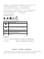
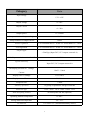
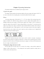
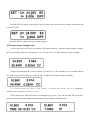
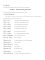
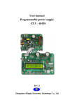
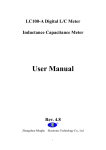
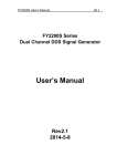
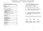
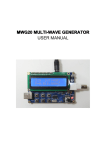
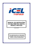
User manual Programmable power supply ZXY - 6020S Rev2.1 Zhengzhou Minghe Electronic Technology Co., Ltd 1 Introduction Safety information Please don’t install replaceable parts in the instrument by yourself, please send it to us to repair , to ensure its security features. Warranty service The company give the product one year quality warranty since the date of shipment.If the product needs to repair,please send it to us. When you send us the warranty product,you need pay the single freight by yourself ,we will pay the return freight. Brief introduction ZXY-6020S is single output programmable switch power supply. Its specification is 60V, 20A, 1200W. It designed by DC-DC modularization ,has a small size and a high output power. Besides, it has equipped with TTL serial interface, provide a serial communication protocol, allows user to secondary development, we can according to your design and test requirements to provide versatile solutions. Main special features and advantages : Based on BUCK structure of switch power supply technology, the work frequency reach up to150 KHZ DC input voltage range : 13V~ 62V, which is suitable for multiple kinds of pre-stage input power supplies Operation key and multi-function encoder combine for the operation, it is convenient and easy to use High accuracy and high resolution: 10 mV / 10 mA Low ripple and low noise Indicator light:constant current( CC) ,constant voltage (CV) and output state (ON) LCD1602 display Adjust voltage and current by adjustment knob and keys Support measuring and displaying output voltage, output current, output power, output electric quantity (AH) and working time Intelligent temperature detection, can connect an external DC12V fan,and control its speed in level 2 5 The minimum voltage difference 2V can still work steadily With output turn off function key ,flexible turn on or off output 10 groups of parameter settings of M0-M9, which can be conveniently called out at any moment Prompt for operation or alarm function of onboard buzzer Convenient and simple three-phase charge intelligent control function of storage battery With TTL serial communication, and improved communication protocol so as to be convenient for centralized control Chapter 1 Constitution of Instrument 1 Constitution of power supply 1.Output state indicator lamp 4.expansion interface for coder 2.DC output 3.expansion interface for output indicator lamp 5.voltage detection expansion interface 6.adjusting knob for coder 3 7.Operating key 8.expansion interface for operating key9 .Serial communication interface 10.LCD liquid crystal display11.Buzzer 12.power supply switch 13.expansion interface for power supply switch 15.connector wire socket 14.connection flat cable 16.power connector wire 17.power connector wire socket 18. external connection fan interface 19.voltage expansion interface 20.DC input 21.power board indicator lamp 22.Filter inductance 2 Introductions for keys key description shown in the following list key Name and function page up key, rapidly setting voltage and current values page down key, rapidly setting voltage and current values <>/M storage/call, cursor moves the key left and right SEL option key, setting preferences OUT/OK Enter key 3 Dimension Power module (including radiator):85mm(length)*63mm(wide)*70mm(high) Control module: 130mm(length)*85mm(wide)*43mm(high) Chapter 2 Technical Specifications This chapter introduces the rated voltage, rated current, rated power and other main technical parameters of ZXY-6020S, and the use storage environment and temperature of ZXY-6020S. 4 Category Data Input Voltage 13V~62V Output Voltage 0~60V Output Current 0~20A Output power 0~1200W Setup resolution of output voltage 10mV Setup resolution of output current 10mA Source regulation CV is less than 0.5% + 10 mV CC is less than 1% + 5 mA Load regulation CV is less than 0.5% + 10 mV CC is less than 1% + 5 mA Output ripple < 50mVpp (Input 54 V, 12 V output, current 8 A) Volatility transmission ratio of 100 Hz < 1/10000 Typical Efficiency Input 54 V, 36 V, output current 8 A The display precision of Voltage, 10mV、10mA Current Display error of Voltage ±1%+50mV Display error of Current ±2%+20mA Response time < 50ms Memory operation 10 groups of parameter storage of M0-M9 Protection type OTP、OVP、OCP、OPP、OAH、OFT Heat-dissipating method heat dissipater and fan (optional) Operating ambient temperature 0~40℃ Storage ambient temperature -20~70℃ use ambient For indoor use , maximum humidity of 80% 5 Chapter 3 Operating Instructions This chapter introduces the use method of power supply in detail. 1. Quick start guide This chapter briefly introduces the operation method of the power supply with output of 24.5V, 5A as a case to ensure that user can rapidly grasp a conventional method of the power supply. 2.Start The input voltage range of this model is 13 V ~ 62 V, the voltage of the pre-stage input power supply is enabled to be within the range, otherwise, the power supply cannot possibly work or is damaged, notably, the power supply is a BUCK power supply, if the voltage of 24.5V is needed to be output, the voltage of more than 26V is input (voltage difference of more than 1V is ensured), then the output of a pre-stage power supply is connected to input terminal behind the machine, and reversing of positive and negative poles is paid attention to. After correct input correction of the power supply is ensured, the above power supply switch can be turned on, and now display screen is lightened and voltage and current preset interface appears. Displayed M0 indicates that preset value stored in M0 is called in currently, if parameters pre-stored in other positions are needed to be called out, <>/M keys can be repeatedly pressed to call the parameters from M1 to M9 out, OFF indicates that the power supply is in off state and E0 indicates that the power supply is normally turned off. 3.Setting the voltage and current value Press the SEL key, the cursor stays in a set value of the voltage , rotary encoder, regulate the voltage to 24.00 V, then press the "< >" key, change the cursor position, regulate the voltage value of 24.50V, as shown in the figure below. 6 Press the SEL key again, cursor stays in the set value of the current, rotary encoder, regulate the the current to 5.00A Press the SEL key again, the cursor will disappears. 4.The operation of output state Connect load, press OUT key, the machine will output normally , when the load resistance is larger, the current will less than 5A , the machine is in CV mode, the CV and ON indicator lamps will light. Change the load,when the current increase to reach to 5A, the instrument is in constant current (CC)state, at this time the voltage is reduced, the CC and the ON indicator lamps will light. It is observed that the power is the product of voltage and current, AH is a cumulative amount,which gradually increase over time. Under output state, when the cursor is not displayed, press the ↓ key can clear the AH. Press the ↑ key to switch into the time display and temperature sensor display, as shown below: 7 5. Output off If you don't need to output, you can press OUT key to cut off the output. Chapter 4 Detail operating instructions This section will detail introduce the use method of power supply. 1. General Introduction When output is not performed and the cursor is not displayed, press↑↓key or rotary encoder to switch different function options, as shown below: (1)SET U-CAL Calibration voltage measurement value. (2)SET I-CAL Calibration current measurement value. (3)SET OTP(E6) Set over temperature protection value. (4)SET OVP(E1) Set regulating voltage upper limit (5)SET OCP(E2) Set regulating current upper limit (6)SET OPP(E3) Set overpower protection value (7)SET OAH(E4) Set overcharge capacity protection value (8)SET OFFTIME(E5) Set overtime protection value (9)---SAVE DATA!--- Save set parameter (10)Start up:OFF Set whether output is on or off when starting up (11)System Recover Recover system (12)Sound Enable:ON Set sound (13)Save Parameter: Save parameter (14)Set Addr. Code Set the address code (15)Set BaudRates Set the baud rate (16)Charge Mode:OFF Set whether charge function is started or not 8 2. Voltage and current calibration function (1) and(2), save set parameter function (9), and recover the factory setting function (11) Function (1), (2) and function (9) is to calibrate voltage and current value and save the parameters, we have calibrated it before delivery ,calibration is not needed under general condition,if necessary, please contact us. If you set the wrong parameter, you can use the function (11), press the OK key to restore factory Settings. 3. OVP and OCP setting function (4) and (5) Function (4) and (5) is to set the maximum voltage and current regulation, The maximum voltage and current of this model are respectively are 120V,10A, if you do not need large upper limit of setting regulation, for example, the upper limit of voltage and current you need is 30V,5A, after setting the OVP and OCP , when you operate the machine the output does not exceed the set values. In the function(4), press OK key can enter the voltage upper limit setting, as shown below, Press the key can adjust the position of cursor ,then rotate the adjusting knob to regulate the voltage to 30.00V. The current limit setting is similar to voltage, after setting, we can use function (13) to save parameters in M0, the setting parameters will be automatically called in at the next time. 4. OTP setting function (3) This machine has an intelligent temperature detection control function ,the temperature detection value is a two digits which can reflect the radiator temperature , it is about 50 at normal temperature of 20℃ , when the temperature increase 8 ℃, the figures will reduce by 1. In the function(3) we can check the current radiator temperature detection value and the set value, the default set value is 0,indicating that the temperature control function is not started, when the power is in the output state, fan work,the power supply will not turn off automatically due to the high temperature. If you want to turn off the output when the radiator temperature is about 100℃ , you can set the OTP = 40 (specific machine may different),therefore, when the temperature above 20℃ the fan start to 9 work , between 20℃ to 60℃ will be automatic control speed , more than 60℃ are running at full speed, the output will be cut off automatically when the temperature reach to 100℃,then it will send an alarm and the screen display error code E6. After setting it ,you need to use the function (13)to save the parameters in M0 . 5. OPP, OAH and OFFTIME setting functions (5), (6) and (7) The three functions is over power protection, over AH protection and overtime protection, the setting method is similar, and with the OPP (overpower protection) as a case, the function of the setting of the OPP is described. After entering OPP setting, the screen display the OPP. The default setting is 0,indicating that the OPP function is not started, set non-zero data can start it, for example, set the maximum power of 20W,you can press the key to select the cursor position, and the adjusting knob or press ↑↓key to regulate the OPP value of 24.50V , after setting, open output, when the actual output power over than 20W it will be cut off output,then it will send an alarm and the screen display error code E3. OAH protection function is mainly used for setting upper limit when charging the battery, the machine will work continuously when it is 0, the OAH protection function will work when it is not 0,when the actual output AH is over than the setting value the it will be cut off output,then it will send an alarm and the screen display error code E4. OFFTIME protection function can enable the power supply cut off the output after setting time, the machine will work continuously when the OFT=0;and if set to be non-0 time,when the working time over the setting time it will be cut off output, then it will send an alarm and the screen display error code E5. The three functions also need to use function (13) to save parameters in the M0 . 6.Output setting function (10) The output is default closed when the machine is turned ON , presses the OUT key to open the output , if you need directly output after start, you can use function (10), makes the Start up: ON ,then it will directly output after starting .you need to use function (13) to save the parameters in M0. 7.Sound set function (12) 10 The default operation sound is open , if you needn't the operation voice prompt and alarm , you can set function (12), makes the Sound Enable: OFF, you need to use function (13) to save the parameters in M0 . 8. Storage parameter function (13) The setting function introduced above from item 3 to 7 will be lost after power off, if you need to save, you need to use the function (13), press OK to save the setting parameters in M0,therefore every operation can automatically call relevant set parameters in. This machine has 10 storage positions from M0 to M9, if you need to save parameters in the M1 ~ M9, press the < > / M key to select the store location you need ,then press OK key to save.If you need call in M1 or others ,you can repeatedly press the < > / M key when the machine is not output and the LCD has no cursor . 9.Communication parameter setting function (14) (15) Function (14) and (15) is setting the address code and communication baud rate, this will introduce in another documents 10.Charging mode function (16) Open the charging mode, the power supply performs charging according to the three-stage mode of common charging for industry, when the battery is full, after buzzer rings out, it automatically enters trickle charge mode, and the charging mode can simultaneously set OTP or OAH and other protect function at the same time . Specific to a 48V12AH lead-acid battery as an example to explain the process of three-stage charging, ① Setting voltage of 58.5 V, current of1.8 A, open the charging mode in the function (16) and save in M0. ② Connect the battery, press OUT key, because the voltage of the battery is low, it can be seen that the battery is in constant current (CC) mode and the current is 1.8A, which is the first stage. ③ When the voltage increase to 58.5 V, the current starts falling,the system is in constant voltage CV mode, which is the second stage. ④ With continuous charging, the current is gradually reduced, when the current is reduced to 1/10 of set value 1.8A, namely, 180mA, and now buzzer rings out, the voltage set value is reduced to 93.75% that of original value, namely 54.8V. Under this voltage, the power supply charges the storage battery in 11 trickle charge mode, which is the third stage. 12.Other important notices ①Storage position M0 is parameter automatically called in during default starting-up, and is automatically called in every starting-up. ② The storage range of each storage position of this power supply is wider, comprising voltage and current set values, various protection setting values, and automatic on or not of starting-up, sound options and others, which are stored in corresponding storage positions, and all storage positions are mutually independent without being mutually influenced. Appendix: Shipping list: ZXY - 6020S host 1 Operation instruction 1 PDF electronic format Zhengzhou Minghe Electronic Technology Co., Ltd 12