1
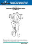
99 Washington Street
Melrose, MA 02176
Phone 781-665-1400
Toll Free 1-800-517-8431
Visit us at www.TestEquipmentDepot.com
GE
Sensing & Inspection Technologies
Druck DPI 705/DPI 705 IS Series
Digital Pressure Indicator
User Manual K0214
English
g
1-6
Test Equipment Depot - 800.517.8431 99 Washington Street Melrose, MA 02176
TestEquipmentDepot.com
©The General Electric Company. All rights reserved
Approved Service Agents
For the list of service centres visit our web site:
Symbols
This equipment meets the requirements of all relevant European
safety directives. The equipment carries the CE mark.
This symbol, on the instrument, indicates that the user should refer
to the user manual.
Do not dispose of this product as household waste. Use an
approved organisation that collects and/or recycles waste electrical
and electronic equipment. For more information:
Contact us at www.gesensinginspection.com
Test Equipment Depot - 800.517.8431 99 Washington Street Melrose, MA 02176
TestEquipmentDepot.com
K0214 Issue No. 5
The Druck DPI 705 pressure indicator uses a micro-machined silicon transducer to
produce a pressure reading in units of pressure measurement. These user instructions
include the operations for all DPI 705 Pressure Indicators, safety instructions and the
requirements for intrinsically safe instruments.
Specification
Accuracy:
Combined non-linearity, hysteresis and repeatability ............................... ±0.1% full-scale (FS)
Temperature effects: Span ............................................................................................. ±0.02%rdg/°C
Zero .............................. <= 1 bar ±0.05%FS/°C (absolute ranges only)
.......................................... > 1 bar ±0.02%FS/°C (absolute ranges only)
Operating range ........................................................................ -10°C to 50°C (15°F to 120°F)
Storage range ............................................................................... -20°C to 60°C (-5°F to 140°F)
Maximum safe working pressure ...................................................................................... 2 x full-scale
Pressure connector ............................................................................. 6 mm o/d and 4 mm i/d hose,
........................................................................................................ G1/8 or 1/8"NPT female thread
Maximum torque ........................................................................................................ 2.259 Nm (20 lb. in)
Environmental ...................................................................................................................... IP54 (NEMA 12)
Electrical safety ........................................................................................... BS EN 61010 as applicable
Electromagnetic compatibility .................................................................. EN50081-1 (emissions)
.................................................................... EN50082-2 (immunity)
Electrical Power Supply for non-certified units ........................................... 3 x 1.5 V alkaline size AA
Safety
This symbol, on the pressure indicator, indicates that the user should
refer to the user guide or manual.
Pressure
Do not apply pressure greater than the maximum safe working pressure.
Do not apply pressure greater than 1.1 bar (15.95 psi) absolute to the -ve
pressure port of differential pressure indicators.
Batteries
Remove batteries from the pressure indicator immediately when
discharged and before storage.
Dispose of batteries in accordance with local regulations and battery
manufacturers' instructions.
When storing and transporting batteries make sure they cannot be short
circuited.
Clean the pressure indicator with a damp cloth.
Refer to the Calibration and Configuration Instructions.
Cleaning
Calibration
Software Version
This manual contains operating instructions
for pressure indicators with software version 1.02 onwards. Further changes
to the pressure indicator's software may require a change to the operating
instructions and an issue number change of the manual.
1
K0214 Issue No. 5
English
DPI 705 Series Digital Pressure Indicator
Introduction
Display Symbols
Batteries are low, replace
observing polarity shown on case
Displayed reading - maximum value
Displayed reading - minimum value
Displayed reading - leakage (per
minute)
Filter applied
(10 reading rolling average)
TARE
A
(flashing)
Tare applied
Alarm - pressure value
more than alarm setting
Leak test in progress
(count down)
Change units (1 of 16
pressure units, °C or °F)
Switch Tare on or off (changes the
display reading to zero)
Switch filter
on or off
View maximum,
minimum or perform leak
test (max/min is reset at
switch on)
Switch
on or off
Operation
TIME OUT
If a key is not pressed within 10 minutes then the instrument times out and switches
off. To disable this automatic time out, hold the LEAK key when switching on the pressure
indicator.
LEAK TEST
To perform a leak test, press the LEAK key 3 times. The
symbol flashes on the
display with the number 60. To start the leak test press the LEAK key again. The
instrument counts down 60 seconds displaying the leakage at the end of the 60 second
period. Press the LEAK key at any time during the leak test to quit and return to normal
measurement.
ZERO
A zero should be performed on gauge and differential instruments before measuring
pressure. To perform a zero: Open all pressure ports to atmospheric pressure. Press
the
and TARE keys together, the display briefly shows ZErO and the instrument
calculates a new zero.
Note: A zero can only be performed on absolute pressure indicators if a vacuum
is first applied to the pressure port.
Alarm
A single alarm can be set to operate when the displayed pressure value rises above the
alarm setting. The alarm causes the display to flash and a beeper to sound for one
minute. Pressing TARE and UNITS keys together displays the alarm value, pressing the
FILTER key increases the alarm value, pressing the UNITS key decreases the alarm
value. When the display shows the required alarm value, press the TARE key to set the
alarm.
K0214 Issue No. 5
2
These instructions detail the requirements for using the DPI 705 Intrinsically Safe
Pressure Indicator in a hazardous area. Read the whole publication before starting.
Special note
This instrument has been certified by ATEX and CSA. The batteries certfiied for use by each
certifying body are different. It is the user's responsibility to use the correct batteries.
Installation Requirements in Hazardous Areas
ATEX Certification
Markings:
Ex ia IIC T4 Ga (-10°C ≤ Ta ≤ +50°C) .............. hazardous location markings
BAS02ATEX1194 ............................................... certificate number
II 1 G
........................... equipment group and category
1180
........................... CE mark
DPI 705 IS .......................................................... specific apparatus type
Pressure range in mbar or psi ....................... full-scale pressure rating
Druck LTD, Groby, LE6 0FH, UK ..................... manufacturer's name and address
SN*******/YY-MM ............................................ serial number and date of
manufacture, year-month
Requirements and Conditions
Batteries
WARNING:
•
ONLY REPLACE BATTERIES IN A SAFE AREA
Power supply only use 3 x LR6 (AA), Duracell PROCELL, Duracell PLUS, ENERGIZER
ULTIMATE or GP SUPERALKALINE.
Installation
WARNING:
DO NOT USE TOOLS ON THE PRESSURE INDICATOR THAT MIGHT CAUSE INCENDIVE
- THIS CAN CAUSE AN EXPLOSION.
SPARKS
•
•
Installation should be carried out by qualified plant installation technicians in
compliance with the latest issue of EN 60079-14.
Provide additional protection for indicators that may be damaged in service.
Declaration Requirements
The DPI 705 IS is designed and manufactured to meet the essential health and safety
requirements not covered by EC Type Examination Certificate BAS02ATEX1194 when
installed as detailed above.
This intrinsically safe instrument is designed and manufactured to protect against other
hazards as defined in paragraph 1.2.7 of Annex II of the ATEX Directive 94/9/EC.
Test Equipment Depot - 800.517.8431 99 Washington Street Melrose, MA 02176
TestEquipmentDepot.com
English
Intrinsically Safe Pressure Indicators
Introduction
CSA Certification
Markings:
Ex ia IIC T4, Class 1, Zone 0 and Class 1, Div.1
Groups A, B, C & D ..................................................... hazardous location designation
1999 LR110032-3 ....................................................... certificate reference
Amb Temp -10°C to +50°C ........................................ ambient temperature range
..................................... CSA monogram
DPI 705 IS .................................................................... specific apparatus type
Pressure range in mbar or psi ................................. full-scale pressure rating
Druck LTD, Groby, LE6 0FH, UK ............................... manufacturer's name and address
SN*******/YY-MM ...................................................... serial number and date of
manufacture, year-month
Requirements and Conditions
Batteries
WARNING:
•
ONLY REPLACE BATTERIES IN A SAFE AREA
Power supply use only 3 x LR6 (AA) made by Eveready Energizer LR6, Varta 4006
or Duracell Procell MN1500.
Installation
WARNING:
•
•
DO NOT USE TOOLS ON THE PRESSURE INDICATOR THAT MIGHT CAUSE INCENDIVE
SPARKS - THIS CAN CAUSE AN EXPLOSION .
Installation should be carried out by qualified plant installation technicians in
compliance with the latest issue of Canadian Electrical Code (CEC).
Provide additional protection for indicators that may be damaged in service.
Maintenance
Note: The following applies to all instruments of the DPI 705 Series.
•
•
Return the instrument to the factory for any repairs, it cannot be repaired on-site.
To keep the DPI 705 accurate to 0.1% full-scale a calibration check should be
carried out once per year.
Cleaning
•
Clean the instrument case with a moist, lint-free cloth and weak detergent.
K0214 Issue No. 5
4
WARNING: CALIBRATE DPI 705 IS INSTRUMENTS IN A SAFE AREA.
The instrument performs a two-point compensation at ZErO and FS (full-scale.)
Preparation
1.
Connect the instrument to
a pressure source
that has an accuracy
three times better than the
instrument.
Recommended:Druck DPI 610 or DPI 610
IS Portable Calibrator.
2.
Switch on the instrument
and select the units of
pressure measurement
required for calibration.
Procedure
1.
Press all three keys
together to enter the
CAL menu and proceed as
shown:
Changing the PIN
Each digit can be changed
in turn.
Pressing:
increases the value
of the digit.
steps to next digit,
left
to right.
enters the PIN
5
K0214 Issue No. 5
English
Calibration Instructions
Test Equipment Depot - 800.517.8431 99 Washington Street Melrose, MA 02176
TestEquipmentDepot.com