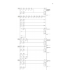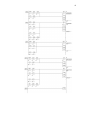
1
PSZ 19:16 (Pind. 1/07)
UNIVERSITI TEKNOLOGI MALAYSIA
DECLARATION OF THESIS / UNDERGRADUATE PROJECT PAPER AND COPYRIGHT
EFEDI BI AWAG
Author’s full name :
29 OVEMBER 1985
Date of birth
:
Title
:
SMART TRAFFIC LIGHT FOR
EMERGECY VEHICLES
Academic Session:
2007/2008
I declare that this thesis is classified as :
CONFIDENTIAL
(Contains confidential information under the Official Secret
Act 1972)*
RESTRICTED
(Contains restricted information as specified by the
organisation where research was done)*
OPEN ACCESS
I agree that my thesis to be published as online open access
(full text)
I acknowledged that Universiti Teknologi Malaysia reserves the right as follows :
1. The thesis is the property of Universiti Teknologi Malaysia.
2. The Library of Universiti Teknologi Malaysia has the right to make copies for the purpose
of research only.
3. The Library has the right to make copies of the thesis for academic exchange.
Certified by :
SIGNATURE
851129-11-5593
(NEW IC NO. /PASSPORT NO.)
Date :
NOTES :
13 MAY 2008
*
SIGNATURE OF SUPERVISOR
DR. HAZLIA BT SELAMAT
NAME OF SUPERVISOR
Date :
13 MAY 2008
If the thesis is CONFIDENTIAL or RESTRICTED, please attach with the letter from
the organisation with period and reasons for confidentiality or restriction.
“I hereby declare that I have read this thesis and in my
opinion this thesis is sufficient in terms of scope and quality for the
award of the degree of Bachelor of Electrical Engineering
(Control & Instrumentation)”
Signature
:
……………………........................
Name of Supervisor
:
DR. HAZLINA BINTI SELAMAT
Date
:
13th MAY 2008
SMART TRAFFIC LIGHT FOR EMERGENCY VEHICLES
EFENDI BIN AWANG
A report submitted in partial fulfilment of the
requirements for the award of the degree of
Bachelor of Electrical Engineering
(Control & Instrumentation)
Faculty of Electrical Engineering
Universiti Teknologi Malaysia
MAY 2008
I declare that this thesis entitled “ Smart Traffic Light for Emergency Vehicles” is the
result of my own research except as cited in the references. The thesis has not been
accepted for any degree and is not concurrently submitted in candidature of any other
degree.
Signature
:
......................................
Name
:
EFENDI BIN AWANG
Date
:
13 MAY 2008
iii
To my beloved mother (Mek binti Embong), father (Awang bin Othman),
and family members
iv
ACKNOWLEDGEMENT
Alhamdulillah, thanks to Almighty ALLAH S.W.T for give me a chance to
complete this thesis. All good aspirations, devotions, and prayers are due to ALLAH
whose blessing and guidance have helped me throughout to entire project.
Firstly, I would like to take this opportunity to express my appreciation to my
supervisor Dr. Hazlina binti Selamat, who are really talented in the instrumentation
field. My supervisor supported me in the way that they were giving help and
encouragement to encounter new challenge in final year project. Her knowledge and
advice have been of great value for me.
Not forgetting also, a word of thanks to Encik Mohamad Syukri bin Abdul
Manaf for his guidance in Programmable Logic Controller (PLC). Besides, thanks to
all PSM committee because of their useful information. Then, I would like to thanks
to University Teknologi Malaysia department for give me a chance to register in final
year project subject.
Then, I would like to thank especially to my beloved parents because of their
sacrifice and support me in the way to finish this thesis. Thanks also to my sisters,
brothers and other families for their loving support.
My special thanks go to Adliany and Hudabiyah because of support and help
me in the way to finish this thesis. My sincere appreciation also extends to Adillah,
Apit, Aizuddin, Sireh, Apat and all my fellow friends of SEI. Their entire companion
is truly appreciated, as it was a great pleasure to have known them.
v
ABSTRACT
This project is introducing the application of the PLC nowadays. PLC is a
black-white relay controller of logic foundation using Ladder Diagram and
Mnemonic codes, with the 3C technology (Computer, Control and Communication)
unifies. Programmable Logic Control is important because all production processes
go through a fixed repetitive sequence of operations. A PLC is used to control, time
and regulate the sequence. In this project, PLC was used to design a T-Junction
traffic light. Sensor was used to sense and give priority to emergency vehicles
through any junction. The sensor will sense the emergency vehicles and give a
signal to PLC to turn on green light for that way. All the red light will turn on for a
while when it change from junction to junction as a safety factor. The traffic light
will be function follow the sequence from junction to other junction starting from
green, yellow and red. Photodiode was used as a sensor. The photodiode sensor will
be mounting at the signboard 200 meter from the traffic light. The photodiode
sensor will turn on when it sense the emergency vehicles. PLC will receive the
signal from the photodiode sensor and will turn on green light at that junction. It
means, the traffic light will give priority to emergency vehicles cross the junction.
Furthermore, the other junctions turn to red.
vi
ABSTRAK
Projek ini memperkenalkan aplikasi Programmable Logic Controller (PLC)
pada masa kini. PLC adalah geganti pengawal hitam putih yang berasaskan logik
menggunakan gambarajah tangga dan kod mnemonik dengan menggabungkan
teknologi 3C (Computer, Control, Communication). PLC amat penting dalam
sesuatu proses kerana ia melibatkan proses yang berturutan untuk membuat sesuatu
keputusan. PLC digunakan untuk mengawal, menetapkan masa dan memanipulasi
sesuatu turutan. Dalam projek ini, PLC digunakan untuk merekabentuk sistem lampu
isyarat lalulintas di simpang tiga. Sistem lampu isyarat tersebut menggunakan
pengesan untuk memberi keutamaan kepada kenderaan kecemasan yang melalui
mana-mana simpang. Pengesan akan mengesan kenderaan kecemasan dan memberi
isyarat kepada PLC untuk menukar aliran lampu isyarat hijau kepada laluan tersebut.
Setiap perubahan dari satu simpang ke simpang yang lain, semua lampu merah akan
menyala untuk seketika sebagai faktor keselamatan. Lampu isyarat berfungsi
mengikut turutan dari simpang ke simpang bermula dari hijau, kuning dan kemudian
merah. Pengesan yang digunakan dalam sistem lampu isyarat ini adalah pengesan
fotodiod. Pengesan fotodiod dipasang pada palang papan tanda pada jarak 200 meter
dari lampu isyarat tersebut. Apabila pengesan mengesan kenderaan kecemasan, ia
akan aktif. Pengesan akan memberi isyarat kepada PLC untuk menukar aliran lampu
hijau kepada simpang tersebut. Ini bermakna, kenderaan kecemasan akan diberi
keutamaan untuk melintas simpang tersebut. Oleh itu, isyarat pada simpang-simpang
yang lain akan bertukar menjadi merah.
vii
TABLE OF CONTENTS
CHAPTER
1
2
TITLE
PAGE
DECLARATION
ii
DEDICATION
iii
ACKNOWLEDGEMENT
iv
ABSTRACT
v
ABSTRAK
vi
TABLE OF CONTENTS
vii
LIST OF FIGURES
ix
LIST OF TABLE
xi
LIST OF APPENDICES
xii
INTRODUCTION
1
1.1
History of Traffic Light
1
1.2
Problem Statement
2
1.3
Objectives
3
1.4
Scope of Work
3
1.5
Outline
4
LITERATURE REVIEW
5
2.1
Introduction
5
2.2
Traffic Light
5
2.2.1 History
5
2.2.2 Priority to Emergency Vehicles
6
2.3
Programmable Logic Controller (PLC)
7
2.4
Traffic Light Sensor
8
2.4.1 Theory of Inductive Loop
8
viii
2.5
3
4
5
2.4.2 Inductive Loop Sensor
10
2.4.3 Principle of Photodiode
11
Accuracy
12
METHODOLOGY
14
3.1
Introduction
14
3.2
Searching Information
14
3.3
Identify Sensor
16
3.3.1 Photodiode Sensor
17
3.3.2 Signal Conditioning Circuit
18
3.3.2.1 Current to Voltage Converter
19
3.3.2.2 First Buffer
20
3.3.2.3 Second Buffer
21
3.3.3 Printed Circuit Board (PCB) Design
21
3.3.4 Laser Pointer and Accuracy of Laser Pointer
25
3.4
Design a Controller and Identify the Component
25
3.5
Develop Hardware
28
RESULT AND DISCUSSION
33
4.1
Output Voltage Sensor
33
4.2
Normal Condition
33
4.3
Sensor Condition
34
4.4
Problems Encountered
35
CONCLUSION AND FUTURE WORK
36
5.1
Conclusion
36
5.2
Future Work
37
REFERENCES
38
APPENDICES
39
ix
LIST OF FIGURES
FIGURE NO
TITLE
PAGE
Figure 2.1
Inductive Loop
8
Figure 2.2
Analogies of Accuracy and Precision
13
Figure 3.1
Block Diagram
15
Figure 3.2
T-Junction Model
16
Figure 3.3
Photodiode Symbol
17
Figure 3.4
Photodiode Sensor
17
Figure 3.5
Signal Conditioning Circuit
18
Figure 3.6
Current to Voltage Converter Circuit
19
Figure 3.7
First Buffer
20
Figure 3.8
Second Buffer
21
Figure 3.9
PCB Circuit
22
Figure 3.10
PCB steps
23
Figure 3.11
Soaking the PCB in the water
23
x
Figure 3.12
Etching Process
24
Figure 3.13
Etched PCB
24
Figure 3.14
State Diagram
27
Figure 3.15
Programmable Logic Controllers (PLC)
28
Figure 3.16
Power Supply for Traffic Light Circuit
29
Figure 3.17
Location of photodiode sensor
29
Figure 3.18
LED circuit
30
Figure 3.19
Complete Signal Conditioning Circuit
31
Figure 3.20
Power Supply for Sensor Circuit
32
Figure 4.1
Flow of Traffic Light
33
Figure 4.2
All Traffic Lights is Red
34
Figure 4.3
Sensor 3 detect when Traffic Light 1 is Green
34
xi
LIST OF TABLE
TABLE NO
Table 3.1
TITLE
I/O table for CX-Programmer
PAGE
26
xii
LIST OF APPENDICES
APPENDIXES
TITLE
PAGE
A
Ladder Diagram
39
B
Cx-Programmer
42
CHAPTER 1
INTRODUCTION
1.1 History of traffic light
The traffic light, also known as traffic signal, stop light, traffic lamp, stopand-go lights, robot or semaphore, is a signaling device positioned at a road
intersections. It use as the road signal for directing vehicular traffic by means of
colored lights, In most countries, the sequence is red (stop), green (go), yellow
(prepare to stop). In some cases, traffic signals also indicate to drivers when they
may make a turn. These signals may be operated manually or by a simple timer
which allows traffic to flow on one roadway for a fixed period of time, and then on
the other road-way for another fixed period of time before repeating the cycle. Other
signals may be operated by sophisticated electronic controllers that sense the time of
day and flow of traffic to continually adjust the sequence of operation of the signals.
Traffic engineers use signals to avoid traffic congestion and improve safety for both
motorists and pedestrians alike.
The first illuminated traffic signal was installed in London, England, in 1868.
It was manually turned and consisted of two gas lamps, one red and one green, with
semaphore arms atop a pole. Shortly after its inauguration it blew up while the lamps
were being lit and killed a policeman. The first electric traffic signal was installed in
Cleveland, Ohio, in 1914. It consisted of a green and red light with a warning buzzer
to indicate when the light was about to change. The first signal to use the familiar
green, yellow, and red lights was installed in New York City in 1918. It was operated
manually from an elevated observation post in the middle of the street. In Los
2
Angeles, traffic lights consisted of green and red lights used in conjunction with a
warning gong and a pair of semaphore arms lettered "stop" and "go."
A modern traffic signal system consists of three basic subsystems: the signal
lights in their housing, the supporting arms or poles, and the electric controller. The
signal lights and housing are known as the signal light stack. A single stack usually
consists of three lights: a green light on the bottom to indicate the traffic may
proceeds, a yellow light in the middle to warn traffic to slow and prepare to stop, and
a red light on the top to indicate the traffic must stop. Because some people are redgreen color blind, there has been an effort to standardize on a vertical stack of lights
with red at the top so that these people can perceive the signal condition by the
position of the light rather than the color.
Each light has a Fresnel lens which may be surrounded or hooded by a visor
to make it easier to see the light in bright sunlight. A Fresnel lens consists of a series
of concentric angled ridges on the outer surface of the lens which bend the light to
focus it in a parallel beam. The light stack may have a dark-colored backing plate to
make the signals more distinguishable by blocking out surrounding lights from
buildings and signs. There are one or more signal light stacks for each direction of
each roadway. The electric controller is usually mounted in a weather-proof box on
one of the corners of the intersection. More elaborate traffic signals may also have
electromagnetic sensors buried in the roadway to detect the flow of traffic at various
points.
1.2
Problem Statement
Before, the traffic light using timer without sensor is an ineffective traffic
light. Usually the traffic light systems in Malaysia use an inductive loop to detect a
car when arrives at an intersection or to control the length of the light. Based on the
research, this system was invented only to smooth traffic flow at the junction. Until
now, these types of systems have not been applied to emergency vehicles. So, there
are many problems for emergency vehicles arriving at the junction with traffic light.
Besides that, emergency vehicles take a lot of time to move in a hectic traffic
3
condition at the junction when traffic light is light. For that reason, there will be risks
to person in need and emergency such as ambulance, fire brigade and police.
1.3
Objectives
The purpose of this project is to design the traffic light system that can sense
emergency vehicles at certain distances and give the priority to them. Based from
study conducted, there are many traffic light junctions in Malaysia. In emergency
situation, emergency vehicles need immediate intention, so they need the priority in
passing through the traffic light junction. Traffic light return green when it detects an
emergency vehicles moving toward it.
Another objective is to develop a hardware model for Smart Traffic Light for
Emergency Vehicles with sensor. This project will be implemented using the
Programmable logic Controller (PLC). At the same time, components that need to be
installed in this traffic light system will be identified. The controller or the traffic
light systems first be simulated using simulation program to ensure the system is
verified. The software that used to simulate the controller is CX-Programmer and
Trilogy.
1.4
Scope of Work
Because the main scope of this project is too wide, it needs to be narrowed to
smaller scope that is suitable for final year project. First, traffic light model is
designed to be implemented a T-Junction. The T-Junction is a tri-directional.
Therefore, the possibility of emergency vehicles coming is in three directions. For
the traffic light characteristics, there is only one junction with green light, other
junction are red. So, the traffic light will be moving from one direction only. It is also
assumed that only one coming from one direction at a time.
4
1.5
Outline
Chapter 2 introduces the various literature reviews that give explanation on
the previous research with have certain similarity with this project. It also include
about the principal and operation of traffic light.
Chapter 3 discusses the methodology for this project regarding how to design
and develop a traffic light system. It consist software and hardware development.
Chapter 4 describes the result and analysis for the traffic light system. It is
also include problem encountered during finishing this project.
Chapter 5 discusses the conclusion that can be made from the result and
recommendation for the future.
CHAPTER 2
LITERATURE REVIEW
2.1
Introduction
The numbers of vehicles enormously increase every year. In big cities, traffic
congestion always happen at traffic light junction. One of the ways to avoid this
event occurs is by replacing the traffic light junctions by fly over. However, not all
the traffic light junction can be replaced by fly over. It is depending on the location
of the junction. Traffic light is a signaling device positioned at a road intersection,
pedestrian crossing or other location in order to indicate when it is safe to drive, ride
or walk using a universal color code. Until now, there are many changes that have
been done to traffic light system. Based on the research findings, there are several
data have been taken as a literature review for the project.
2.2
Traffic light
2.2.1 History
On 10 December 1868, the first traffic lights were installed outside the British
Houses of Parliament in London, by the railway engineer J. P. Knight. They
resembled railway signals of the time, with semaphore arms and red and green gas
lamps for night use. The gas lantern was turned with a lever at its base so that the
appropriate light faced traffic. Unfortunately, it exploded on 2 January 1869, injuring
the policeman who was operating it.
6
The modern electric traffic light is an American invention. As early as 1912
in Salt Lake City, Utah, policeman Lester Wire invented the first red-green electric
traffic lights. On 5 August 1914, the American Traffic Signal Company installed a
traffic signal system on the corner of 105th Street and Euclid Avenue in Cleveland,
Ohio. It had two colors, red and green, and a buzzer, based on the design of James
Hoge, to provide a warning for color changes. The design by James Hoge allowed
Police and Fire stations to control the signals in case of emergency. The first fourway, three-color traffic light was created by police officer William Potts in Detroit in
1920.
2.2.2 Priority to emergency vehicles
Some regions have signals that are interruptible, giving priority to special
traffic. Such traffic light preemption is usually reserved for emergency vehicles such
as fire brigade, ambulance and police, though sometimes mass transit vehicles
including buses and light rail trains can interrupt lights. Most of the systems operate
with small transmitters that send radio waves, infrared signals or strobe light signals
that are received by a sensor on or near the traffic lights. Some systems use audio
detection, where a certain type of siren must be used and detected by a receiver on
the traffic light structure.
Upon activation the normal traffic light cycle is suspended and replaced by
the ‘preemption sequence’: the traffic lights to all approaches to the intersection are
switched to ‘red’ with exception of the light for the vehicle that has triggered the
preemption sequence. Sometimes, an additional signal light is placed nearby to
indicate to the preempting vehicle that the preempting sequence has been activated
and to warn other motorists of the approach of an emergency vehicle. The normal
traffic light cycle resumes after the sensor has been passed by the vehicle that
triggered the preemption. In lieu of pre-emptive mechanisms, in most jurisdictions,
emergency vehicles are not required to respect traffic lights, but must activate their
own emergency lights when crossing an intersection against the light, in order to
alert oncoming drivers to the preemption.
7
In one recent Oregon incident (2005) a fire pre-empted a signal at a light rail
crossing and proceeded to collide with a light-rail train. A subsequent inquiry
determined that the light-rail driver was at fault, falsely believing that once the LRT
has obtained the right-of-way across an intersection, it could not be lost until the train
had cleared the intersection normally, this was the case, but pre-emption by an
emergency vehicle was an exception to the rule.
2.3
PLC (programmable logic controller)
PLC (programmable logic controller) is the control hubs for a wide variety of
automated systems and processes. They contain multiple inputs and outputs that use
transistors and other circuitry to simulate switches and relays to control equipment.
They are programmable via software interfaced via standard computer interfaces and
proprietary languages and network options.
Programmable logic controllers I/O channel specifications include total
number of points, number of inputs and outputs, ability to expand, and maximum
number of channels. Number of points is the sum of the inputs and the outputs. PLC
may be specified by any possible combination of these values. Expandable units
may be stacked or linked together to increase total control capacity. Maximum
number of channels refers to the maximum total number of input and output channels
in an expanded system. PLC system specifications to consider include scan time,
number of instructions, data memory, and program memory. Scan time is the time
required by the PLC to check the states of its inputs and outputs. Instructions are
standard operations (such as math functions) available to PLC software. Data
memory is the capacity for data storage. Program memory is the capacity for control
software.
8
2.4
Traffic light sensor
2.4.1 Theory of Inductive Loop
Some lights do not have any sort of detectors. For example, in a large city,
the traffic lights may simply operate on timers. No matter what time of day it is,
there is going to be a lot of traffic. In the suburbs and on country roads, however,
detectors are common. They may detect when a car arrives at an intersection, when
too many cars are stacked up at an intersection (to control the length of the light), or
when cars have entered a turn lane (in order to activate the arrow light).
There are all sorts of technologies for detecting cars. Everything from lasers
to rubber hoses filled with air. By far the most common technique is the inductive
loop. An inductive loop is simply a coil of wire embedded in the road's surface. To
install the loop, the asphalt was lay and then come back and a groove was cut in the
asphalt with a saw. The wire is placed in the groove and sealed with a rubbery
compound.
Figure 2.1
Inductive loop
Inductive loops work by detecting a change of inductance. There is a battery,
a light bulb, a coil of wire around a piece of iron (yellow), and a switch. The coil of
wire is an inductor.
9
If the inductor out of this circuit, the bulb will lightning a normal flashlight.
When the switch is closed, the bulb will be turn on. With the inductor in the circuit as
shown, the behavior is completely different. The light bulb is a resistor. The wire in
the coil has much lower resistance, so when the switch is on, the bulb glow very
dimly. Most of the current should follow the low-resistance path through the loop.
When the switch is closed, the bulb burns brightly and then gets dimmer. When the
switch is open, the bulb burns very brightly and then quickly goes out.
The reason for this strange behavior is the inductor. When current first starts
flowing in the coil, the coil wants to build up a magnetic field. While the field is
building, the coil inhibits the flow of current. Once the field is built, then current can
flow normally through the wire. When the switch gets opened, the magnetic field
around the coil keeps current flowing in the coil until the field collapses. This current
keeps the bulb lit for a period of time even though the switch is open. The capacity
of an inductor is controlled by two factors, the number of coils and the material that
the coils are wrapped around.
Putting iron in the core of an inductor gives it much more inductance than air
or any other non-magnetic core would. There are devices that can measure the
inductance of a coil, and the standard unit of measure is the Henry.
So, if the coil of wire perhaps 5 feet in diameter, containing five or six loops
of wire were placed on the road, and then insert a piece of metal in the loop. The
induction value was recorded and compared with the inductance value when a car
was replaced. The inductance will be much larger because of the large steel object
positioned in the loop's magnetic field. The car parked over the coil is acting like the
core of the inductor, and its presence changes the inductance of the coil.
A traffic light sensor uses the loop in that same way. It constantly tests the
inductance of the loop in the road, and when the inductance rises, it knows there is a
car waiting.
10
2.4.2 Inductive Loop Sensor
The main triggered technology used in red-light systems in the induction loop.
An induction-loop trigger is a length of electrical wire buried just under the asphalt.
Usually, the wire is laid out in a couple of rectangular loops resting on top of each
other in Figure. This wire is hooked up to an electrical power source and a meter.
When an electrical current flow through a wire, a magnetic field will be generate.
Positioning the wire in concentric loops, as in any electromagnet, amplifies this field.
This sort of field affects not only objects around the loop, but also the loop
itself. The magnetic field induces an electrical voltage in the wire that is counter to
the voltage of the circuit as a whole. This significantly alters the flow of current
through the circuit.
The intensity of this induction depends on the structure and composition of
the loop; changing the layout of the wires or using a different conductive material
(metal) will change the loop’s inductance. The inductance also can change the
inductance by introducing additional conductive materials into the loop’s magnetic
field. This is what happens when a car pulls up to the intersection. The huge mass of
metal that makes up your car alters the magnetic field around the loop, changing its
inductance.
The meter in the system constantly monitors the total inductance level of the
circuit. When the inductance changes significantly, the computer recognizes this shift
and knows that a car has passed over the loop. This is the most common trigger
mechanism, but it is not the only one in use. Some areas have had success with radar,
laser or air-tube sensors.
One emerging trigger mechanism is the video loop. In this system, a
computer analyzes a video feed the intersection. As the computer receives each new
video frame, it checks for substantial changes at specific points in the image. The
computer is programmed to recognize the particular changes that indicate a car
11
moving through the intersection. If the light is red and the computer recognizes this
sort of change, it activates the still cameras. The main advantage of this system is
doing not have to dig up the road to install it, and can adjust the trigger areas at any
time. Essentially, it is a virtual inductive-loop trigger.
2.4.3 Principal of photodiode
A photodiode is a p-n junction or p-i-n structure. When a photon of sufficient
energy strikes the diode, it excites an electron thereby creating a mobile electron and
a positively charged electron hole. If the absorption occurs in the junction's depletion
region, or one diffusion length away from it, these carriers are swept from the
junction by the built-in field of the depletion region, producing a photocurrent
Photodiodes can be used under either zero bias (photovoltaic mode) or
reverse bias (photoconductive mode). In zero bias, light falling on the diode causes a
current across the device, leading to forward bias which in turn induces "dark
current" in the opposite direction to the photocurrent. This is called the photovoltaic
effect, and is the basis for solar cells. In fact, a solar cell is just a large number of big
photodiodes.
Reverse bias induces only little current (known as saturation or back current)
along its direction. But a more important effect of reverse bias is widening of the
depletion layer (therefore expanding the reaction volume) and strengthening the
photocurrent. Circuits based on this effect are more sensitive to light than ones based
on the photovoltaic effect and also tend to have lower capacitance, which improves
the speed of their time response. On the other hand, the photovoltaic mode tends to
exhibit less electronic noise.
Avalanche photodiodes have a similar structure, but they are operated with
much higher reverse bias. This allows each photo-generated carrier to be multiplied
by avalanche breakdown, resulting in internal gain within the photodiode, which
increases the effective responsively of the device.
12
2.5
Accuracy
Accuracy is the degree of conformity of a measured or calculated quantity to
its actual (true) value. Accuracy is closely related to precision, also called
reproducibility or repeatability, the degree to which further measurements or
calculations show the same or similar results. The results of calculations or a
measurement can be accurate but not precise; precise but not accurate; neither; or
both. A result is called valid if it is both accurate and precise. The related terms in
surveying are error (random variability in research) and bias (non-random or directed
effects caused by a factor or factors unrelated by the independent variable).
Accuracy is the degree of veracity while precision is the degree of
reproducibility. The analogy used here to explain the difference between accuracy
and precision is the target comparison. In this analogy, repeated measurements are
compared to arrows that are fired at a target. Accuracy describes the closeness of
arrows to the bull’s eye at the target center. Arrows that strike closer to the bulls’ eye
are considered more accurate. The closer a system's measurements to the accepted
value, the more accurate the system is considered to be.
To continue the analogy, if a large number of arrows are fired, precision
would be the size of the arrow cluster. (When only one arrow is fired, precision is the
size of the cluster one would expect if this were repeated many times under the same
conditions.) When all arrows are grouped tightly together, the cluster is considered
precise since they all struck close to the same spot, if not necessarily near the bull’s
eye. The measurements are precise, though not necessarily accurate.
13
Figure 2.2
Analogies of Accuracy and Precision
CHAPTER 3
METHODOLOGY
3.1
Introduction
In this subtopic, it will discuss the method used to achieve the objective and
specification. There are four parts in accomplishing this project. First parts are about
searching information of traffic light and sensor and understand those system works.
Then, parts two are identify the suitable sensor to use in order to sense an emergency
vehicle. Third parts are designing the controller and identify the components to build the
hardware model. The last parts are simulating the traffic light system and develop
hardware model.
3.2
Searching information
First step in conducting a project is to the back ground of the current traffic light
system and the history of the traffic light. From the definition, traffic light is the system
that control vehicles in traffic intersection of two or more roadways by giving a visual
indicator to driver when to proceed, when to slow and when to stop. The literature
review gives basic and detailed information that is vital to gather understanding. All data
collected will be documented after the validating of the information is confirmed. This
literature is collected from journal, books, past year thesis and internet. The traffic light
system work must be understood overall in order to modify the current system.
15
Figure 3.1
Block diagram
Figure 3.1 shows the flow of designing the traffic light system. First, the
controller of traffic light system will be designed by using CX-Programmer. Then, the
controller program will convert to the PLC. After that, PLC will run the program of the
traffic light system as shown in figure 3.2. Each junction has two traffic light indicators.
16
Figure 3.2
T-Junction Model
Lastly, when the sensor detect the laser from emergency vehicles, the flow of
normal condition of traffic light will be interrupted and change the traffic flow.
3.3
Identify sensor
This traffic light system will sense emergency vehicles and give priority to them
cross the junction. So, choosing the suitable sensor for emergency vehicles is very
important in sending the data from transmitter to receiver. Based on finding, photodiode
is most suitable sensor to be applied in this project. It is because, the cost of photodiode
device, maintenance, training and overall operation are much lower and competitive.
Compare to Radio Frequency Identification (RFID) sensor, the RFID sensor cost is more
expensive and it function is similar to photodiode function that is to trigger or switch the
PLC. So, for this project, photodiode is most suitable and effective.
17
3.3.1 Photodiode Sensor
Figure 3.3
Photodiode symbol
Figure 3.4
Photodiode sensor
Figure 3.4 shows the photodiode sensor. This sensor can convert light to either
current or voltage. It looks like light emitting diode (LED) that has two leads or wires,
coming from the bottom. The shorter end of the two is the cathode while the longer end
is the anode. The higher intensity of light will produce the higher value of voltage.
18
3.3.2 Signal Conditioning Circuit
The signal conditioning circuit is used to investigate the changing of light
intensity. Basically, the signal conditioning circuit consists of current to voltage
converter and signal amplification.
A current to voltage converter is used to convert the light detected by the sensor
into electrical signal. The current generated by the photodiode is proportional to the
intensity of light. The higher intensity of light will produce higher of current.
Generally, the signal conditioning circuit can be divided into three stages. Figure
3.5 shows the overview of signal conditioning circuit.
Figure 3.5
Signal Conditioning Circuit
19
3.3.2.1 Current to Voltage Converter (stage 1)
Figure 3.6
Current to Voltage Converter Circuit
Figure 3.6 represents the current to voltage converter circuit for the signal
conditioning used in this project. LM 308, CA3140 or FET input type operational
amplifier (op amp) are the most suitable low input bias op amp can be use for this circuit
in order to obtain steady DC indication for the light levels.
The value chooses for the component will give approximately 14/mV/cm2
irradiation for the signal. The value of R1 and R2 can be reduced for less sensitivity but
it should kept equal while the 1000pF capacitors can be increase to reduce ripple as the
result from AC lighting or to control the response time as well.
20
3.3.2.2 First buffer (stage 2)
Figure 3.7
First Buffer
For the second stage, another op amp will be used to provide a DC gain and at
the same time it will act as a buffer.
21
3.3.2.3 Second buffer (stage 3)
Figure 3.8
Second Buffer
With the same concept as stage 2, a similar circuit with different value of input
and feedback resistance was connected to the output of stage 2. This value will give the
maximum gain up to 10 times the signal of stage 2. By using rotational potentiometer for
the feedback resistance, the gain at this stage can be varied.
3.3.3 Printed Circuit Board (PCB) Design
Printed circuit has been choosing as a medium for constructing a circuit.
Although there are many ways to construct the circuit, PCB is the best ways due to its
simplicity and easy to build.
The layout of the signal conditioning circuit is designed by using Eagle. Eagle has
been choosing due to its simplicity and easy to use. However, Eagle is not suitable to be
implementing for complex circuit.
Each sensor required one signal conditioning circuit. Four signal conditioning
circuit has been developed for this project but just three sensor will and the last one just
22
to spare if any problem occur during demonstration. Two boards are used, which means
each board consists two sensors. There are several steps that been implemented in order
to build the PCB.
Figure 3.9
PCB Circuit
23
The steps of process constructing the PCB is shown in figure 3.10:-
First, the layout was printed on photo
paper
The printed layout was laminated on
PCB using laminating machine
The PCB was soaked in the water for
several minutes
Lastly, remove the copper layer from
PCB using Ferric Chloride. This process
is called etching
Figure 3.10
Figure 3.11
PCB steps
Soaking the PCB in the water
24
Figure 3.12
Figure 3.13
Etching Process
Etched PCB
25
3.3.4 Laser Pointer and Accuracy of Laser Pointer
For demonstration, laser pointer is used to interrupt the photodiode sensor. But,
for real live, laser is placed at the top of emergency vehicles and the direction of this
laser is vertical. Although all vehicles have light, but the light direction of those vehicles
is horizontal and do not affect the photodiode sensor.
According to signal conditioning circuit, the value of output voltage is not
important but, the circuit has set the set point value so that the PLC will trigger and
change the traffic light flow when the current value reaches the set point value. It means,
the output voltage below the set point value is not give any effect to the traffic light
system
3.4
Design a Controller and Identify the Component
The next methods are to design controller for traffic light system that can sense
emergency vehicles. The controller was created in state machine diagram as shown in
figure 3.14 where three different directions of an emergency vehicle were applied. The
initial condition for the traffic lights is red. This traffic light worked in sequence from
junction to junction starting from green, yellow and red. After finishing the controller
design, the components of the traffic light system was identified. Identifying the
component in traffic light design is needed before developing the hardware.
26
I/O table for CX-Programmer
Table 3.1
IPUT
RELAY
TIMER
OUTPUT
Symbol
Address
Symbol
Address
Symbol
Time
Address
Symbol
Address
S1
0000
Z0
2000
T0
3s
TIM000
R1
1000
S2
0001
Z1
2001
T1
10s
TIM001
Y1
1001
S3
0002
Z2
2002
T2
3s
TIM002
G1
1002
Z3
2003
T3
3s
TIM003
R2
1003
Z4
2004
T4
10s
TIM004
Y2
1004
Z5
2006
T5
3s
TIM005
G2
1005
T6
3s
TIM006
R3
1006
T7
10s
TIM007
Y3
1007
T8
3s
TIM008
G3
1100
T9
15s
TIM009
T10
15s
TIM010
T11
15s
TIM011
27
R1
Y 1G1
Z3
T9
Z4
T10
Z5
T11
start
S 2 S1S 3Z 3Z 5
Y 2G 2
R2
Y 3G3
T 8Z 4
R3
Y 3Z 0 Z 1
T6
Y3
Z0
T0
Z 0G1
T 0Z 4Z 5
G 3Z 3
T 7Z 5
G 3Z 4
T 8Z 4
G1
T1
G1Y 1
T7
G3
G 3Y 3
T 5Z 3
G1Z 4
T 6Z 3Z 4
G1Z 5
T 1Z 3
T 2Z 5
Y1
T8
T2
Z2
Z 2G3
Y 1Z 1Z 2
T 2Z 5
T 5Z 3
G 2Z 3
Y 2 Z 0Z 2
T 3Z 3Z 5
Y2
T 4Z 4
Z1
T3
G2
T5
G 2Y 2
Z 1G 2
G 2Z 5
T4
Figure 3.14
3.5
State Diagram
Develop hardware
The last part of methodology is simulating the system and develops the
hardware. The system must be simulated by computer program. The computer
program that will be used is CX-Programmer and the I/O table this controller is
shown in table 3.1. This part is very important before developing the hardware. The
purpose of simulating the system is to verify the system is valid and safe to be used.
28
In the end of this project, the developed hardware hopefully will be implemented in
Malaysia traffic light system.
Figure 3.15
Programmable Logic Controllers (PLC)
Figure 3.15 shows the PLC device that used to run the traffic light system. It
has 16 inputs and 22 outputs. The LED circuit will connect to PLC output. There are
nine outputs and three inputs were used in this project.
29
Figure 3.16
Power Supply for Traffic Light Circuit
The LED circuit needs power supply 9V to turn on traffic light LEDs. The
LED dim was adjusted by the voltage.
Figure 3.17
Location of photodiode sensor
30
The photodiode sensor was placed about 200 meter from traffic light in real
live and this sensor was located at the top of main entrance road as shown in figure
3.17. When the emergency vehicle cross this main entrance, the PLC will trigger and
change the traffic light flow.
Figure 3.18
LED circuit
On the LED circuit, there were 18 resistors with each value is 220ohm was
used to avoid the over current.
31
Figure 3.19
Complete Signal Conditioning Circuit
Signal conditioning circuit in figure 3.19 is used to sense the laser from
emergency vehicles. The power for this circuit is ± 15 V and the output voltage from
this circuit can be 0-15V and it can be adjusted by potentiometer.
32
Figure 3.20
Power Supply for Sensor Circuit
The power supply in figure 3.20 is used for supply the sensor circuit. The
connections from the sensor circuit were -15V, +15V and ground (GND).
CHAPTER 4
RESULT AND DISCUSSION
The traffic light is design for T-Junction only. So, the traffic light changed
from green, yellow and red. For the normal condition, when there is not sensor sense
the laser, the traffic light was run by using timer. The green color is on about
10second. Then the yellow color is on about 3second. For the red color, it still on
until it turn to green back again.
4.1
Output Voltage Sensor
After do the experiment for circuit sensor, there are differential for output
voltage when gives a laser to photodiode. Because the power supply for LED is 9V,
the output voltage is needed to trigger the PLC is above 9V. So, the set point is set
about 9V. For normal condition, the output voltage is set 7.353V. Then, when gives
the laser to photodiode, the output voltage reaches about 9.57V. So, it’s enough to
make the PLC trigged.
4.2
Normal Condition
2
1
1
2
3
2
3
1
Figure 4.1
Flow of Traffic Light (1 to 2 to 3)
3
34
In normal condition in figure 4.1, the traffic flow from traffic light 1 and then
to traffic light 2 and the last to traffic light 3. Then the flow will rotate from traffic
light 1 again. The initial condition for all traffic lights is red for a while. When one
traffic light is green, the vehicles from other roads cannot go straight or turn left or
right.
1
2
3
Figure 4.2
All traffic lights is red
After finishing the green and yellow color for one junction, all the traffic light
will be red in 3second for safety factor like figure 4.2. After that, the traffic light will
go to the next turn of traffic light.
4.3
Sensor Condition
2
1
2
3
3
1
Figure 4.3
Sensor 3 detect when traffic light 1 is green
In sensor condition as figure 4.3, if there is not sensor sense the laser from
emergency vehicles, the traffic light will flow in normal condition. If the sensor
detects emergency vehicles from any direction, the priority to green light will give to
the road that was detected by sensor. The green light is on until the emergency
35
vehicle cross the junction. For example in figure 4.3, the traffic light is green for
traffic light 1, then sensor 3 is detect the emergency vehicle, the output voltage
reaches or achieve 9V and trigger the PLC. The traffic light green will change to the
traffic light 3. The same situation also happens to another junction if the sensor
before flow is green light detects an emergency vehicle.
If the sensor at green traffic light was detected an emergency vehicle, the
traffic light is not going to be yellow and red, but the green light timer for this
junction will extend 15second. So, it’s enough to emergency vehicles take a time to
cross the junction.
4.4
Problem Encountered
During this project, there are several problems was happened. First, the Radio
Frequency Identification (RFID) cannot be used in this project because it is
expensive. Furthermore, the function of RFID is similar to photodiode sensor that is
less expensive compare to RFID.
Second, the problems come from signal conditioning circuit. The output
voltage from the sensor circuit is unstable. Besides, the IC CA3140 or FET is very
sensitive and easy to damage. Lastly, light from surrounding may also affect the
output voltage of the sensor circuit. This problem can be solved by adjusting the
potentiometer to ensure the value of output voltage exceed 9V when the sensor is
detected.
CHAPTER 5
CONCLUSION AND FUTURE WORK
5.1
Conclusion
In order to achieve the objectives of the project, the model was designed and
simulated successfully using the PLC. It shows that PLC has many advantages in
term of cost effectiveness, flexibility, powerful computer capabilities and reliability.
The PLC also can interface of communicate with another PLC or a computer system
for data interchanged. Hence, it also rugged toward electric noise, anti shock, anti
jamming, moisture and uncomfortable surrounding.
The traffic light work in sequence as it was programmed and the sensor also
fully operate as planned. The traffic light flow was continuous from traffic light 1,
traffic light 2 and traffic light 3. The sequence will be repeated. In term of safety
aspect, each junction of traffic light become red before the other junction is green.
Besides, the sensor for each junction has the ability to change traffic flow when it
detect emergency vehicle. Apart from that, the traffic light system can sense
emergency vehicles at certain distances and give priority to them.
Overall, using the PLC and photodiode sensor has possibility to operate
Smart Traffic Light System for Emergency Vehicles smoothly. Besides, it may also
depend on the controller of traffic light.
37
5.2
Future Work
For the recommendation, this traffic light system can be applied on the cross
junction to see the efficiency of the system. The designing controller of the traffic
light may different at certain cross junction.
To a better design of traffic light, the pedestrian walk can be included. This
designed is suitable to be implemented at busy junction. So, it is easy to pedestrian
cross the road safely.
The system could be connected to emergency command center. This system
will guide the emergency vehicles until it reach their destination.
38
REFERECES
[1]
John E. Ridley. Mitsubishi FX Programmable Logic Controllers. Elsevier,
1992.
[2]
Dr. Eric M. Schwartz. Traffic Light Controller.Canada. University of Florida,
2006.
[3]
John Dovdell. Smart Traffic Light.JD On EP, 2004.
[4]
John W. Webb, Programmable Logic Controllers. Principles and
Applications. New York: Macmillan, 1988.
[5]
Ryan G. Rosandich, “What to Know About PLC Ladder Diagram
Programming” EC&M Jun. 1996: 20.
[6]
Omron User Manual and Installation Guide, 1989.
[7]
Dunning, G., “Introduction to Programmable Logic Controllers”, Delmar
Thomson Learning Inc., 2002.
[8]
Pallas-Areny, R., Webster, J., G., “Sensors and Signal Conditioning”,
John Wiley & Sons, 2001.
[9]
Frank D. Petruzella, Programmable Logic Controllers, 2nd Edition. McGraw
Hill. New York. 1996
39
APPEDICES
Appendix A Ladder Diagram
40
41
42
Appendix B Cx-Programmer
.