1
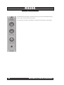
RS290
SAMPLER/DELAY
ECHO/DELAY
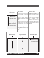
Echo was almost certainly the earliest 'effect' used on electronic sounds. It is also the easiest to produce:
all you need is a tape recorder with a record head offset by a few centimetres from the playback head. If
you then record a sound onto the tape, you can replay it as a single echo a few fractions of a second later,
with the delay determined by the tape speed and the distance between the heads. Later innovations
included machines with multiple heads that produced a series of echoes, and tape loop systems that - if
you wished - extended the number of echoes to infinity, each sounding muddier and less like the original
sound than the previous. If you listen to the electronic music of the 1950s, you'll find it awash with tape
echo, sometimes used to excellent effect, more often not.
The problem with tape echo was that it was neither convenient nor cheap to produce. A lighter and more
affordable alternative arrived in the 1970s with the development of the bucket brigade device, or BBD.
Although totally analogue in nature, a BBD takes a series of samples of the incoming audio, and allows
you to tap these at various stages as they pass down a series of discrete steps through the device. BBDs
made cheap electronic delay lines a commercial reality and, although they never sounded as good as
their tape-based counterparts, solid state "echo units" soon became a staple of electronic music.
Although the maximum delay times available from BBD echo units tended to be rather short - of the
116
ANALOGUE SYSTEMS RS-INTEGRATOR
order a few hundred milliseconds - they proved to be ideal for a wide range of electronic effects such as
chorus, flanging and phasing, whereupon their often metallic sound could prove to be a benefit rather
than a hindrance. The Analogue Systems RS310 Reverb/Chorus is one such device and, unlike the standalone units developed in the '70s, this offers significant benefits such as voltage control of the delay time
and voltage control of the mix between the unaffected and affected signals.
Offering far higher fidelity, digital delay lines (DDLs) were also developed in the 1970s. Although clunky
by today's standards, the earliest of these were unbelievably expensive, which is why they did not come
to the attention of most musicians for another decade or so. To explain precisely how a digital delay line
works would require a thorough treatise on sampling theory, and this manual is not the correct place for
that. Nonetheless, it's not hard to grasp the basics…
A digital delay line is nothing more nor less than a specialised computer that samples an incoming signal
and stores it in RAM. These samples are typically taken at a rate of 44,100 times per second, and stored
with a resolution of 16- or 24- bits per sample. Once a sample is held, it can be read back at any time (or
times) determined by the delay algorithm, until it is necessary to replace it with another incoming sample.
The amount of time a sample can be stored is determined by the amount of RAM in the system.
If you can modulate the clock rate of a DDL and mix the affected signal with the original, you can create
a much wider range of effects than just simple delays. As on their analogue counterparts, this is the
method used to recreate sounds such as chorusing, flanging and phasing.
SAMPLER
Like the digital effects units mentioned above, digital samplers use computer memory to store clips of
audio that have been converted into digital form by an analogue-to-digital converter. Playing back these
clips is simply a matter of reversing the process, reading the information in the memory and converting
this - as accurately as possible - back into the original audio.
It this were the limit to the capabilities of a digital sampler, it would not be a particularly useful tool.
However, if we vary the rate at which the memory is read during the playback process, we can alter the
pitch of the audio, transposing the sound up and down. So, for example, if an audio clip was sampled at
a clock rate of 44,100 times per second, but played back at 22,050 samples per second, the resulting sound
would have a pitch exactly one octave lower than the original. Clearly, if we could control the clock rate
using a keyboard (or other controller of some sort) we could 'play' the audio clip just like the waveform
produced by a conventional, analogue oscillator.
In the 1970s, early users of the newly developed sampling technology were carried away by this idea,
and transposed many vocal and instrumental sounds inappropriately, producing an effect sometimes
called 'munchkinisation'. This arises when the nature of the clip is altered too much by the transposition,
making the tonal qualities unsuitable for the pitch that is being produced. The solution to this was to
develop instruments capable of recording and storing multiple clips, and distributing these clips across
the range of pitches required.
'Multi-sampling' required more powerful processors and a significant increase in memory, so early
performance samplers such as the Fairlight CMI were extremely expensive. But the cost of hardware
diminished rapidly throughout the 1980s and 1990s, and manufacturers can now design low-cost devices
that offer a huge range of sampling, editing, and replay capabilities. The RS290 is one such device, and
although it is a single-voice sampler, its unique combination of digital sampling, computer-based sample
manipulation and control via analogue CVs makes it a unique product that allows you to experiment
with sound in ways that are not possible elsewhere.
ANALOGUE SYSTEMS RS-INTEGRATOR
117
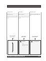
Show delay time
(press "EDIT")
Show delay time
Delay Options
(press "EDIT")
Clock settings
(press "EDIT")
Sample rate
(press "EDIT")
Delay Options
Clock Settings
Sample Rate
Delay time
Press EDIT
Sample Size
LFO
Delay range
Show BPM
Damping
Show delay time
Left/right delay
Sync to clock
External feedback
Assign 1
Mode menu
Assign 2
Clock source
Clocks per beat
CANCEL
Special Options
Tape Delay
- or Digital Delay
9.8kHz 26.8s
Mode
Memories
Mode
Sampler
46.9kHz 5.6s
Delay time display
Delay Options menu
Clock settings menu
Sample rate selector
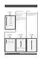
Memories
(press "EDIT")
Sample record
(press "EDIT")
Sampler options
(press "EDIT")
Transmit sysex dump
(press "EDIT")
Memories
Sample record
Write to memory
Start recording
Record start
Read from memory
Stop recording
Record stop
Transmit sysex deump
Edit memory name
Play sample
Playback method
Sample rate
Enable prog change
Playback start
Sample size
SysEx dump memory
Playback stop
Sampler options
Special options
Press EDIT
CANCEL
Transmit sysex dump
Select to send
Erase all memories
Memories menu
Sample record menu
Sampler options menu
SysEx dump menu
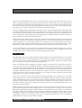
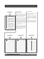
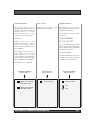
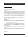
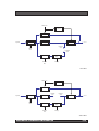
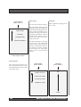
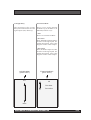
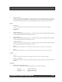
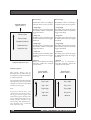
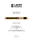
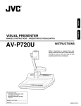
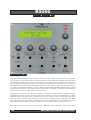
RS290 menu structure: v2.8, dated 9 April 2007
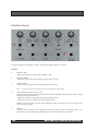
IN USE
The RS290 is in many ways two separate products. On one hand, it's a sophisticated Delay unit with six
distinct modes of operation, and its inputs, controls and menus act in ways that are most appropriate for
using it in this fashion. However, a quick change to Sampler mode alters the front panel operation and
substitutes the eleven Delay menus and numerous sub-menus with eight Sampler menus and sub-menus
that allow you to use it as a powerful, voltage controlled, single-voice sampler.
There is some overlap between the operation and menu structures in the two modes, so the rest of this
chapter is divided into three sections:
•
•
•
118
Common menus
Menus and commands specific to the Delay modes
Menus and commands specific to the Sampler mode
ANALOGUE SYSTEMS RS-INTEGRATOR
Sample size
(press "EDIT")
16 bits
LFO
(press "EDIT")
Assign 1
(press "EDIT")
Assign 2
(press "EDIT")
Damping
Damping
Sample rate
Sample rate
Range
Speed
Sample size
Sample size
Delay fine
Delay fine
Shape
Disabled
Disabled
Controls
LFO Speed
LFO Speed
Depth
Special options
(press "EDIT")
Show input level
Show output level
Set MIDI channel
Memories
(press "EDIT")
Write to memory
Read from memory
Edit memory name
Calibrate keyboard
Enable prog change
Show version
SysEx dump memory
Upgrade firmware
Sync Mode
4 bits
LFO Depth
LFO Depth
Left/right delay
Left/right delay
Left/right pan
Sample size selector
LFO menu
Assign 1 menu
Sample rate
(press "EDIT")
Sample size
(press "EDIT")
Special options
(press "EDIT")
46.9kHz 5.6s
16 bits
Left/right pan
Assign 2 menu
Show pot values
Erase all memories
Factory defaults
Special options menu
Memories menu
Show input level
Show output level
Set MIDI channel
Calibrate keyboard
Show version
Upgrade firmware
Show pot values
9.8kHz 26.8s
4 bits
Sample rate selector
Sample size selector
Factory defaults
Special options menu
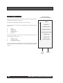
NAVIGATION
The RS290 is controlled primarily by the menus displayed on its 2 line x 20 character LCD. This display
is backlit to aid its use in darkened conditions.
The two main menus (the top level of each menu hierarchy) offer access to the sub-menus, which in turn
may offer additional sub-sub-menus. (The sub-sub-menus are not shown above.)
•
•
•
•
•
Navigate through any menu by rotating the EDIT knob.
Move "down" to select a sub-menu by pressing the EDIT knob.
Enter a value and return to the previous menu by pressing the EDIT knob.
Jump "up" a level from a sub-menu to a main menu by pressing CANCEL.
Leave an option or parameter unchanged and return to the menu containing it by pressing
CANCEL.
ANALOGUE SYSTEMS RS-INTEGRATOR
119
COMMON MENUS
Mode
(press "EDIT")
(Refers to v2.8)
There are five sub-menus that are
common to the Tape delay, Digital
Delay and Sampler modes.
•
•
•
•
•
Tape delay
Mode
Sample rate
Sample size
Special options
Memories
Digital delay
Sampler
Of these, Mode, Sample rate and
Sample size offer all their options
within the sub-menu itself. In
contrast, Special Options and
Memories have extensive sub-submenus.
Mode menu
Mode
This menu allows you to switch
between Tape delay, Digital
delay and Sampler modes.
When you do so, all settings are
remembered, so you can return
to the previous mode and find
that its dedicated menus and
settings are in the same state as
you left them.
120
ANALOGUE SYSTEMS RS-INTEGRATOR
Sample rate
(press "EDIT")
Sample size
(press "EDIT")
46.9kHz 5.6s
16 bits
9.8kHz 26.8s
4 bits
Sample rate selector
Sample size selector
Sample rate
Sample size
You may select the sample rate
of the digital audio data stored
and used within the RS290.
You may select the sample size
(or 'wordlength') used within the
RS290.
You can not set the sample rate
independently for the Delay and
Sampler modes, and the value set
in this menu will be used by both.
You can not set the sample size
independently for the Delay and
Sampler modes, and the value set
in this menu will be used by both.
The time (in seconds) shown to
the right of the sample rate is the
amount of sample time available
at the selected sample rate.
Higher sample sizes increase
fidelity, while lower sizes
increase the 'grittiness' of the
sound, and offer additional
creative options.
ANALOGUE SYSTEMS RS-INTEGRATOR
121
Special options
(press "EDIT")
Show input level
Show output level
Set MIDI channel
Calibrate keyboard
Show version
Upgrade firmware
Show pot values
Factory defaults
Show input level
Show output level
Set MIDI channel
These display the levels of the
signals presented to the SIGNAL
IN input and provided at the
OUT L output, respectively.
For optimum results, the signals
should lie in the "+" range. If
either signal lies below this in the
"-" range, you should check the
input level and, if necessary,
increase the INPUT GAIN or the
level offered by the device
providing the signal.
(Requires Analogue Systems RS295
Delay Expander module)
The channel set here is used
throughout the RS290 and RS295.
You cannot set it independently
for the Delay and Sampler
modes.
The selected MIDI channel is
used for both SysEx dumps and
program change commands.
Peaking in the * range is
acceptable, but if either display
shows the "!" symbol, the signal
will be clipping, and unpleasant
distortion may result.
Special options menu
Show input level
(press "EDIT")
Show output level
(press "EDIT")
-------+++++
-------+++++
****!!
****!!
Set MIDI channel
(press "EDIT")
1
16
122
ANALOGUE SYSTEMS RS-INTEGRATOR
Calibrate keyboard
Show version
Upgrade firmware
This option allows you to
calibrate the RS290 so that, in
Sample mode, you can play the
sample from an "x" V/Oct
keyboard and have it track
correctly across a wide range.
Display the version of the
operating system loaded.
This option allows you to
upgrade the firmware that lies at
the heart of the RS290.
If you answer "Yes", the device
will show:
Flash programmer
Waiting for data...
To calibrate:
Apply a CV of 0v to the
ASSIGN/SAMPLE
PITCH
input, select "Apply 0V to
Sample pitch input" and then
press SELECT.
If you are unable to present the
new software to the MIDI Input
on the RS295 Delay Expander,
the RS290 will lock up.
Next, apply a CV of 3V to the
same input (on a 1V/Oct
keyboard play a note three
octaves higher than before),
select "Apply 3V to Sample pitch
input", and then press SELECT.
DO NOT WORRY.
Switch off the RS290, wait a few
seconds, and switch on again. It
will then function as before.
The RS290 is now calibrated.
Calibrate keyboard
(press "EDIT")
Apply 0V to assign
then press Edit
Show version
(press "EDIT")
Vx.x dd.mm.yy
Upgrade firmware
(press "EDIT")
Are you sure?
NO
Apply 3V to assign
then press Edit
ANALOGUE SYSTEMS RS-INTEGRATOR
Yes
123
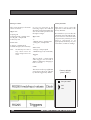
Show pot values
The screen displays the knob
values as follows.
Upper row:
• Input gain
• Repeat speed / Sample start
• F/B gain / Sample end
• Wet/Dry mix
Lower row:
• Assign / Sample pitch
• RS295 Assign 2 (if connected)
Note:
The Wet/Dry mix value is
only shown when the
Bypass on/off switch is set
to On.
Factory defaults
If CVs are received at the
following inputs, the readouts
show the values generated by the
sum of the knob positions and
the input voltages.
Upper row:
•• Repeat speed / Sample start
• F/B gain / Sample end
•-
This allows you to reset the
operation of the RS290 to the
factory defaults.
Be careful how you use this; the
operation cannot be undone and,
if you wish to re-use effects that
you previously created, you will
need to reprogram or (if
appropriate) reload any of your
own effects, sounds or settings.
Lower row:
• Assign / Sample pitch
• RS295 Assign 2 (if connected)
Triggers:
The two dash "-" marks report
when triggers are received at
TRIG1 or TRIG2 by changing to
hash "#" marks.
Clock:
The asterix in the top righthand
corner shows the clock, which is
by default triggered by TRIG1.
Factory defaults
(press "EDIT")
Are you sure?
NO
Yes
124
ANALOGUE SYSTEMS RS-INTEGRATOR
Memories
(press "EDIT")
Write to memory
Read from memory
Write to memory
Edit memory name
You may write your current
settings (but not sample data) to
any one of the 50 internal
memories.
With this menu selected you can
rotate the EDIT knob to move left
and right across the memory
name.
Rotate the EDIT knob to cycle
through the memory locations,
and press it to store your current
setup.
Press the EDIT knob to select the
character you wish to edit, then
rotate it clockwise or anticlockwise to scan through the
alphanumeric table.
Edit memory name
Enable prog change
SysEx dump memory
Erase all memories
Memories menu
Warning…
this
operation
overwrites any existing settings and
parameter values, which will be
permanently lost unless saved
elsewhere beforehand.
You may insert a character into
the selected position by pressing
EDIT again.
Read from memory
Rotate the EDIT knob to cycle
through the memory locations,
and press it to recall a saved
setup.
Write to memory
(press "EDIT")
Read from memory
(press "EDIT")
1
1
Edit memory name
(press "EDIT")
Edit memory name
xxxxxxxxxxxxxxxx
50
50
ANALOGUE SYSTEMS RS-INTEGRATOR
125
Enable prog change
Sysex dump memory
Erase all memories
(Requires Analogue Systems RS295
Delay Expander module)
(Requires Analogue Systems RS295
Delay Expander module)
Clears all fifty memory locations.
• Yes
Press EDIT to dump the
currently active memory via
SysEx.
The RS290 will respond to MIDI
program change messages in the
range 1 to 50, selecting the
memory of that number.
This operation overwrites any
existing settings and parameter
values, which will be permanently
lost unless stored beforehand.
This operation cannot be undone,
and all information stored within the
RS290 will be lost unless it has been
archived elsewhere using the
RS295's SysEx capabilities.
Note that the unit receiving the
information must be ready to
accept the SysEx dump, or it will
not be stored.
• No
The RS290 will not respond to
MIDI program change messages.
Enable prog change
(press "EDIT")
Yes
Sysex dump memory
(press "EDIT")
Select to send
Erase all memories
(press "EDIT")
Are you sure?
NO
No
Yes
126
ANALOGUE SYSTEMS RS-INTEGRATOR
THE DELAY MODES
The RS290 provides two delay modes; one which echoes the operation of a vintage tape delay, and the
other of which is that of a modern digital delay unit.
Tape delay
In Tape delay mode, the operation is very similar to a true tape delay, on which the delay time is determined
by the speed of the tape as it passes across the heads, and is controlled by speeding up the tape and
slowing it down, as appropriate. This makes it possible to create unusual effects that are not as common
today as they were thirty years ago. For example, if the tape is running slowly (you have a long delay
time) and you then speed up the tape the delay time will decrease and the pitch of the delayed sound
will increase. Once the whole loop of tape has run through the machine, the delay time will stay at its
new, faster rate, but the pitch of the delayed sound will drop back to the input pitch. Extending this idea
a bit further, imagine that you increase the tape speed and then quickly decrease it. The pitch will increase
and then decrease. Then, as the loop is replayed on its next revolution a few seconds later, the opposite
will happen; the pitch will decrease, then increase.
The Tape delay mode on the RS290 imitates this unusual behaviour, thus making it possible to create all
manner of unusual effects. However, due to the nature and complexity of the algorithm needed, you
may experience the generation of digital artefacts. You may wish to avoid these, or alternatively use
them to create extreme sounds, as you choose.
Digital delay
If you think of the Digital delay mode in analogue terms it differs from the Tape delay in the following
manner:
•
In Tape delay mode, changes in delay time and pitch are caused by changing the tape speed,
while the distance between the heads remains constant.
•
In Digital delay mode the ‘tape’ runs at a fixed speed but the distance between the heads varies.
Digital delay mode is capable of creating larger pitch shifts, but the shift only occurs while the virtual
‘tape head’ (delay time) is being moved. As soon as you stop changing this, the pitch at the output
returns to the input pitch.
One novel consequence of this is that, if you increase the delay time quickly enough, you can make the
RS290 play the sound backwards briefly. (To visualise this, imagine moving the head faster than the tape
is moving).
The incidence of artefacts in much smaller in Digital delay mode than in Tape delay mode, but you may
still experience some at extreme settings.
Delay Sub-Modes
Both types of delay offer three sub-modes of operation (for a total of six delay modes) as described in the
following pages.
ANALOGUE SYSTEMS RS-INTEGRATOR
127
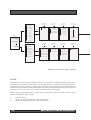
DELAY SUB-MODES
Wet/dry mix
Inverter
Amplifier
OUT R
Amplifier
L/R delay time
Signal IN
Amplifier
Signal
Level
Delay
Amplifier
OUT L
Low-pass
filter
Amplifier
Feedback
Gain
Damping
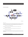
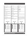
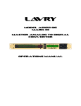
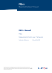
Stereo Delay
(Refers to v2.8)
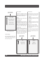
The RS290 offers three delay sub-modes, selected using the Delay Options menu. There are myriad ways
in which you will be able to use these to create new sounds and effects; far more than can be described
here. To help you to understand these, the signal path diagrams show the three configurations:
•
Stereo delay (no external feedback loop)
The RS290 acts as a stereo delay unit, with two taps presented to the Left and Right outputs.
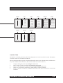
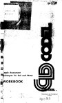
•
Mono delay ('Pre' effect loop)
With this selected, you can patch external effects and treatments into the regeneration loop.
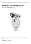
•
Mono delay ('Post' effect loop)
With this selected, you can patch external effects and treatments into the signal path following the output
from the delay itself. As in 'Pre' mode, these will affect the regeneration loop, but will also affect the
output signal.
128
ANALOGUE SYSTEMS RS-INTEGRATOR
Wet/dry mix
Inverter
Amplifier
Signal IN
Amplifier
Delay
Amplifier
OUT L
Feedback
send
Signal
Level
Feedback
return
Low-pass
filter
Amplifier
Feedback
Gain
Damping
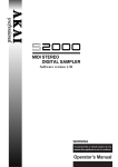
'Pre' effect
Wet/dry mix
Inverter
Amplifier
Feedback
send
Signal IN
Amplifier
Delay
Signal
Level
Amplifier
Feedback
Gain
Feedback
return
Amplifier
OUT L
Low-pass
filter
Damping
'Post' effect
ANALOGUE SYSTEMS RS-INTEGRATOR
129
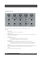
THE FRONT PANEL
In the delay modes, the front panel controls, inputs and outputs operate as follows:
Controls
•
INPUT GAIN
Adjusts the input level in the range -80dB to +3dB
•
REPEAT SPEED
Adjusts the delay time. To keep quantisation noise to a minimum, use as short a delay range as
possible for your desired delay
•
F/B GAIN
Controls the feedback gain.
- With the knob turned fully anticlockwise, the Gain is zero.
- With the knob turned fully clockwise, the Gain is unity.
•
WET/DRY MIX
Controls the amount of wet (affected) and dry (original) signal in the output mix.
- With the knob turned fully anticlockwise, the output comprises input signal only.
- With the knob turned fully clockwise, the output comprises delayed signal only.
•
BYPASS
When switched to Bypass, this determines that the output contains no affected signal. It is
equivalent to rotating the WET/DRY MIX knob to its fully anticlockwise position.
•
ASSIGN
This input can be assigned various functions
130
ANALOGUE SYSTEMS RS-INTEGRATOR
Inputs
•
SIGNAL IN
Accepts audio signals in the range ±3V. Signals in excess of 6V p-p will cause clipping.
•
F/B RETURN
Accepts audio signals in the range ±3V. Signals in excess of 6V p-p will cause clipping.
Note:
The Feedback return is effective only when one of the external feedback modes are enabled in the
menus.
•
REPEAT SPEED CV
Accepts control voltages in the range -5V to +5V. The incoming voltage is added to that determined
by the REPEAT SPEED knob immediately above it.
•
F/B GAIN CV
Accepts control voltages in the range -5V to +5V. The incoming voltage is added to that determined
by the F/B GAIN knob immediately above it.
•
ASSIGN CV
Accepts control voltages in the range -5V to +5V. The incoming voltage is added to that determined
by the ASSIGN knob immediately above it.
•
TRIG1
Apply pulses in the range +1.5V to 20V to this input for use as a clock or LFO 'sync' reset.
•
TRIG2
Apply pulses in the range +1.5V to 20V to this input for use as a clock or LFO 'sync' reset.
Outputs
•
OUT L
Outputs a signal in the range ±2.25V. Signals in excess of 4.5V p-p may be clipped.
•
OUT R / F/B SEND
Depending upon the Delay Mode, this acts as the output for the right audio channel (stereo
delay sub-mode) or as the Send for an external feedback loop ('Pre' and 'Post' sub-modes).
Indicators
•
LEVEL (Signal IN & Signal OUT)
These offer visual feed back regarding the signal level at input and output.
- LED off
- LED green/amber
- LED red
very low signal level
optimum signal level
clipping is occurring
ANALOGUE SYSTEMS RS-INTEGRATOR
131
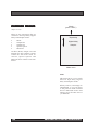
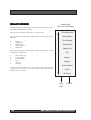
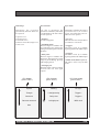
DELAY MENUS
The following pages outline the menu structure in the Delay modes,
and detail all the options available.
The top level of the menu heirarchy is as shown here.
Five sub-menus are common to both the Delay and Sampler modes.
These are:
•
•
•
•
•
Default Delay
(Top Level 0f Heirarchy)
Show delay time
Delay Options
Clock Settings
Mode
Sample rate
Sample size
Special options
Memories
Sample Rate
Sample Size
The following pages will, therefore, explain the functions of the
remaining six sub-menus:
•
•
•
•
•
•
Show delay time
Delay Options
Clock Settings
LFO
Assign 1
Assign 2
LFO
Assign 1
Assign 2
Special Options
Of these, Show delay time offers no sub-sub-menus. The other five
sub-menus have extensive sub-sub-menus, with each offering
additional sets of options.
Mode
Memories
Press
’EDIT’
132
CANCEL
ANALOGUE SYSTEMS RS-INTEGRATOR
Show delay time
(press "EDIT")
Delay time
Delay time display
Show delay time
This sub-menu displays the
delay time to four decimal places
(i.e. to an accuracy of one ten
thousandth of a second).
This menu has no sub-menus.
ANALOGUE SYSTEMS RS-INTEGRATOR
133
Delay Options
(press "EDIT")
Delay range
Damping
Left/right delay
External feedback
Delay range
Damping
You may select from four ranges.
Select feedback damping from
0% to 100%
The exact nature of the ranges is
dependent upon the sample rate
selected in the Sample Rate submenu. At the maximum rate of
46.9kHz, the ranges offer delays
lying between 0.0001s to 5.59s. At
the minimum sample rate of
9.8kHz, the ranges lie between
0.005s and 26.85s.
The Repeat Speed front-panel
control will work within the
selected range, with the fastest
repeats (i.e. the shortest delay) at
the clockwise extreme, and the
slowest repeats (i.e. the longest
delay) at the anticlockwise
extreme.
Delay Options menu
Delay Options
This sub-menu provides four
sub-sub-menus that allow you to
control the primary nature of the
echo/delay effect.
Delay range
(press "EDIT")
0.0001s to 0.01s
Damping
(press "EDIT")
0%
0.0010s to 0.06s
0.0100s to 0.56s
0.0999s to 5.59s
100%
134
ANALOGUE SYSTEMS RS-INTEGRATOR
Left/right delay
External feedback
The percentage of the overall
delay time between the left and
right outputs (50%=halfway)
Allows you to use the external
feedback loop (F/B SEND - F/B
RETURN) in three ways:
• Off:
There is no external feedback
• Pre effect:
The F/B SEND output lies before
the effect in the signal path. For
further information, refer to the
diagrams earlier in this chapter.
• Post effect:
The F/B SEND output lies after
the effect in the signal path. For
further information, refer to the
diagrams earlier in this chapter.
Left/right delay
(press "EDIT")
0%
External feedback
(press "EDIT")
Off
Pre effect
Post effect
100%
ANALOGUE SYSTEMS RS-INTEGRATOR
135
Clock settings
(press "EDIT")
Show BPM
Show delay time
Sync to clock
Clock source
Clocks per beat
Clock settings menu
Sync to clock
Clock source
Determines whether the delay
effect is synchronised to an
external clock and the input from
which the clock is derived.
Determines the source for the
clock signal used within the
RS290. There are three options:
• Off
The delay is not synchronised to
an external clock.
• Synchronise
The repeat speed is controlled by
the REPEAT SPEED knob, but
any increase or decrease in the
speed of the external clock will
cause a corresponding increase
or decrease of the repeat speed.
• Lock to XX
The repeat speed is locked to a
fraction of the external clock
frequency. For example, if "lock
to 3" is selected, the input will
repeat once every three beats.
The fraction "XX" is controlled by
the REPEAT SPEED knob.
• Trigger1
A stable set of triggers received
at the TRIG1 input will be used
as the clock.
• Trigger2
A stable set of triggers received
at the TRIG2 input will be used
as the clock.
Midi clock (requires RS295)
A MIDI Clock signal received at
the RS295 MIDI IN will be used
as the clock.
Note: When receiving a clock signal
a star in the top right hand corner of
the display will flash at half the clock
frequency .
Clock settings
This sub-menu provides five
sub-sub-menus that allow you to
control other characteristics of
the echo/delay effect.
136
Sync to clock
(press "EDIT")
Clock source
(press "EDIT")
Off
Trigger 1
Synchronise
Trigger 2
Lock to XX
MIDI clock
ANALOGUE SYSTEMS RS-INTEGRATOR
Clocks per beat
Show BPM
Show delay time
Determines how many clocks
there are per beat.
Displays the incoming clock in
Beats Per Minute.
Displays the current delay time.
You cannot adjust the delay time
here.
If the clock source is set to MIDI
clock this should normally be set
to "1".
If no clock is detected, the
message "Waiting for clock" is
shown.
Clocks per beat
(press "EDIT")
Show BPM
(press "EDIT")
1
XXX.XX
Show delay time
(press "EDIT")
x.xxxx Seconds
- or Waiting for clock
16
ANALOGUE SYSTEMS RS-INTEGRATOR
137
LFO
(press "EDIT")
Range
Speed
Depth
LFO Range and Speed
LFO Depth
Three LFO ranges are provided:
This menu determines the depth
of the LFO effect applied to the
selected destination in the 'LFO
Controls' sub-sub-menu.
• 0.0005Hz - 0.128Hz
• 0.005Hz - 1.28Hz
• 0.05Hz - 12.8Hz
Within each of these ranges you
can determine the speed of the
internal LFO using the LFO
speed menu.
Shape
Controls
Sync Mode
LFO menu
LFO range
(press "EDIT")
0.0005 to 0.128Hz
LFO speed
(press "EDIT")
0.001 / 0.01 / 0.05 Hz
LFO Depth
(press "EDIT")
0%
0.005 to 1.28Hz
0.05 to 12.8Hz
0.128 / 1.28 / 12.80Hz
(Range dependent)
138
100%
ANALOGUE SYSTEMS RS-INTEGRATOR
LFO Shape
LFO Controls
Sync mode
Determines the waveform
generated by the LFO. There are
five options:
Use this to determine the
parameter of the delay effect that
is modulated by the LFO. There
are four options:
Determines whether the LFO is
synchronised to an external
source, and what that source is.
There are four options:
• Nothing
No LFO is applied
• No sync
The LFO 'free runs' and produces
a continuous waveform
• Square wave
• Triangle wave
• Sawtooth wave
• Reverse sawtooth (ramp) wave
• Sine wave
• Left/Right delay
The LFO signal is added to the
left/right delay ratio, altering the
timing relationship between the
channels
• Delay time
The LFO signal is added to the
delay time. This generates a wide
range of pitch shifting, phasing
and flanging effects
• Trigger1
The LFO is reset by a suitable
signal applied to the TRIG1 input
• Trigger2
The LFO is reset by a suitable
signal applied to the TRIG2 input
• MIDI clock (RS295 required)
The LFO is reset every 24 midi
clocks
• Left/right pan
The LFO signal controls panning
between the left and right
outputs
LFO Shape
(press "EDIT")
LFO Controls
(press "EDIT")
LFO Sync mode
(press "EDIT")
Square
Nothing
No sync
Triangle
Left/right delay
Trigger 1
Sawtooth
Delay time
Trigger 2
Reverse sawtooth
Left/right pan
MIDI clock
Sine
ANALOGUE SYSTEMS RS-INTEGRATOR
139
Assign 1
(press "EDIT")
Assign 2
(press "EDIT")
• Damping
Controls the amount of feedback
damping.
Damping
Damping
Sample rate
Sample rate
Sample size
Sample size
Delay fine
Delay fine
Disabled
Disabled
LFO Speed
LFO Speed
LFO Depth
LFO Depth
Left/right delay
Left/right delay
Left/right pan
Left/right pan
Assign 1 menu
Assign 2 menu
• Sample rate
Steps through the available
sample rates. This can cause
extreme effects, and should be
used with care.
• Sample size
Steps through the available
wordlengths. This can cause
extreme effects, and should be
used with care.
• Delay fine
Allows you to modulate the
delay time.
• Disabled
Disables the effect of the applied
CV.
Assign 1
Assign 2
This sub-menu offers eight
destinations for the CV applied
to the ASSIGN CV input.
This sub-menu is identical to
Assign 1, and offers eight
destinations for the CV applied
to the ASSIGN2 CV input found
on
the
RS295
DELAY
EXPANDER.
• LFO speed
If the RS295 expander is not
connected then the Assign 2
menu will not appear.
• LFO depth
This menu has no sub-menus.
This menu has no sub-menus.
Affects the speed of the internal
LFO, allowing further CV control
of the delay time, left/right delay
ratio, and left/right pan.
Affects the depth of the internal
LFO, allowing further CV control
of the delay time, left/right delay
ratio, and left/right pan.
• Left/right delay
Directly affects the left/right
delay ratio.
• Left/Right pan
Directly affects the left/right pan.
140
ANALOGUE SYSTEMS RS-INTEGRATOR
SAMPLER MODE
The RS290 is unlike any conventional digital sampler. Its combination of sampling with voltage control
of record start/stop, playback start/stop, and playback/loop points is unique, and allows you to create
sounds and effects not available elsewhere.
The RS290 will store a single clip of audio with a maximum length of 26.8 seconds. You can sample the
clip manually, or use one of a selection of triggers to start and stop the sampling process. If you use
electronic record and playback triggers, you can take samples dynamically, updating the stored data and
replaying this in a variety of ways not possible using conventional samplers.
There are numerous playback modes, including the standard one-shot, looped and alternating modes.
You can set the start and stop times (i.e. the range of the audio data) used for playback, and modify these
settings dynamically using control voltages. This allows you to selected different snippets of the sampled
audio.
ANALOGUE SYSTEMS RS-INTEGRATOR
141
THE FRONT PANEL
In Sample mode, the front panel controls, inputs and outputs operate as follows:
Controls
•
INPUT GAIN
Adjusts the input level in the range -80dB to +3dB
•
SAMPLE START
Adjusts the start point for the sample playback and/or loop
•
SAMPLE END
Adjusts the end point for the sample playback and/or loop
Note:
•
If the end point is less than the start point the sample will not play
WET/DRY MIX (Affects OUT L only)
Balances the audio signal being received at the SIGNAL IN input with the output of the existing
sample (if being played back).
- When fully anticlockwise (DRY) only input signal is heard
- When fully clockwise (WET) only the sample is heard
When no signal is being received at the SIGNAL IN input, this knob acts as an output level
control for the sampler.
•
142
BYPASS
When switched to Bypass, this determines that the output contains only input signal. It is
equivalent to rotating the WET/DRY MIX knob to its fully anticlockwise position.
ANALOGUE SYSTEMS RS-INTEGRATOR
•
SAMPLE PITCH
Allows you to play back the sample at various pitches. If you have calibrated the 0V - 3V keyboard
scale correctly (see Common Menus / Special Options) you will be able to play the sample in
conventional fashion. You may also input non-keyboard control voltages for special effects.
Inputs
•
SIGNAL IN
Accepts audio signals in the range ±3V. Signals in excess of 6V p-p will cause clipping.
•
F/B RETURN
Not used.
•
SAMPLE START CV
Accepts control voltages in the range -5V to +5V. The incoming voltage is added to that determined
by the SAMPLE START knob immediately above it.
•
SAMPLE END CV
Accepts control voltages in the range -5V to +5V. The incoming voltage is added to that determined
by the SAMPLE END knob immediately above it.
•
SAMPLE PITCH CV
Accepts control voltages in the range -5V to +5V. The incoming voltage is added to that determined
by the SAMPLE PITCH knob immediately above it.
•
TRIG1
Apply pulses in the range +1.5V to 20V to this input for use as a clock or LFO 'sync' reset.
•
TRIG2
Apply pulses in the range +1.5V to 20V to this input for use as a clock or LFO 'sync' reset.
Outputs
•
OUT L
Outputs a signal in the range ±2.25V. Signals in excess of 4.5V p-p may be clipped.
•
OUT R / F/B SEND
Outputs a 50/50 mix of the existing sample (if played) and the signal presented to the SIGNAL
IN input.
Indicators
•
LEVEL (Signal IN & Signal OUT)
These offer visual feed back regarding the signal level at input and output.
- LED off
- LED green/amber
- LED red
very low signal level
optimum signal level
clipping is occurring
ANALOGUE SYSTEMS RS-INTEGRATOR
143
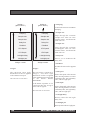
SAMPLE MENUS
Default sampler
(Top Level 0f Heirarchy)
The following pages outline the menu structure in Sample mode,
and detail all the options available.
Mode
The top level of the menu heirarchy is as shown here.
Five sub-menus are common to both the Delay and Sampler modes.
These are:
•
•
•
•
•
Mode
Sample rate
Sample size
Special options
Memories
Sample record
Sampler options
Transmit sysex dump
The following pages will, therefore, explain the functions of the
remaining three sub-menus:
•
•
•
Memories
Sample record
Sampler Options
Transmit Sysex dump
Sample rate
Sample size
Special options
Of these, Transmit Sysex dump offers no sub-sub-menus. The other
two sub-menus have sub-sub-menus, with each offering additional
options.
Press
’EDIT’
144
CANCEL
ANALOGUE SYSTEMS RS-INTEGRATOR
Sample record
(press "EDIT")
• Start recording
Press the EDIT knob to start
recording an audio clip
• Stop recording
Start recording
Stop recording
Press the EDIT knob to stop
recording an audio clip
• Play sample
Play sample
Press the EDIT knob to replay the
audio clip just recorded
Note:
While recording, the RS290 shows
the progress of the recording by
displaying the screen below. This
means that you will not see the "Stop
recording" option.
Sample record menu
Sample record
This menu allows you to record
and play back audio clips under
manual control. For it to be
active, you must set up the
"Record start", "Record stop" and
"Playback start" sub-sub-menus
in the "Sampler options" submenu, as shown on the next
page.
ANALOGUE SYSTEMS RS-INTEGRATOR
Start recording
(press "EDIT")
RECORDING
******
145
Sampler options
(press "EDIT")
Record start
Record stop
Playback method
Playback start
Playback stop
Sampler options menu
Record start
Record stop
Determines when a recording is
initiated. There are five options:
Determines when a recording is
complete. There are five options:
• Trig1 high
Recording starts when the signal
presented to TRIG1 exceeds the
trigger threshold
• Trig1 high
Recording stops when the signal
presented to TRIG1 exceeds the
trigger threshold
• Trig1 low
Recording starts when the signal
at TRIG1 falls below the trigger
threshold
• Trig1 low
Recording stops when the signal
at TRIG1 falls below the trigger
threshold
• Trig2 high
Recording starts when the signal
presented to TRIG2 exceeds the
trigger threshold
• Trig2 high
Recording stops when the signal
presented to TRIG2 exceeds the
trigger threshold
• Trig2 low
Recording starts when the signal
at TRIG2 falls below the trigger
threshold
• Trig2 low
Recording stops when the signal
at TRIG2 falls below the trigger
threshold
•Manual
Allows you to initiate a recording
manually within the "Sample
record" menu
•Manual
Allows you to conclude a
recording manually within the
"Sample record" menu
Record start
(press "EDIT")
Record stop
(press "EDIT")
Sampler options
This menu allows you to
determine how an audio clip will
be sampled, and how and when
it will be replayed.
You will need to set these options
appropriately before you use the
"Sample record" menu described
on the previous page.
Trig 1 high
Trig 1 high
Trig 1 low
Trig 1 low
Note:
Trig 2 high
Trig 2 high
If you have "Record start" and
"Record stop" set to the same value,
the triggers become toggles. This
means that triggering the input will
start recording if the sampler is not
already recording, otherwise it will
stop recording. The "Playback start"
and "Playback stop" commands
work in the same way.
Trig 2 low
Trig 2 low
Manual
Manual
146
ANALOGUE SYSTEMS RS-INTEGRATOR
Playback method
Playback start
Playback stop
Determines the manner in which
the audio clip is replayed. There
are five options:
Determines when a playback is
initiated. There are five options:
Determines when a playback is
concluded. There are five
options:
• Once
Once triggered, the clip is played
once and then stops
• Loop
Once triggered, the sample loops
continuously until stopped
• Reverse once
Once triggered, the clip is played
backward once and then stops
• Reverse loop
Once triggered, the sample loops
backward continuously until
stopped
• Alternate loop
Once triggered, the sample loops
continuously, first playing
forwards and then backwards,
until stopped
Playback method
(press "EDIT")
• Trig1 high
Playback starts when the signal
presented to TRIG1 exceeds the
trigger threshold
• Trig1 low
Playback starts when the signal
at TRIG1 falls below the trigger
threshold
• Trig1 high
• Trig1 low
• Trig2 high
• Trig2 low
As "Playback start", but to stop
the playback.
•Auto
• Trig2 high
Playback starts when the signal
presented to TRIG2 exceeds the
trigger threshold
• Trig2 low
Playback starts when the signal
at TRIG2 falls below the trigger
threshold
•Immediate
Playback starts immediately a
recording is completed
Playback start
(press "EDIT")
Playback method: once, reverse once:
The sample will play once then
stop
Playback method: any 'loop' mode:
The sample will keep playing
until you start recording another
sample, or until you trigger
Playback start to restart playback
from the beginning of the
sample/loop.
Playback stop
(press "EDIT")
Once
Trig 1 high
Trig 1 high
Loop
Trig 1 low
Trig 1 low
Reverse once
Trig 2 high
Trig 2 high
Reverse loop
Trig 2 low
Trig 2 low
Alternate loop
Immediate
Auto
ANALOGUE SYSTEMS RS-INTEGRATOR
147
Transmit sysex dump
(press "EDIT")
Transmit sysex dump
Select to send
SysEx dump menu
Transmit Sysex dump
You may dump the current
sample to an external MIDI
recorder using SysEx.
Press the EDIT knob to initiate
transfer. The message "Sending
Sample" will be displayed,
together with the percentage of
the total data transmitted. On
completion, the screen will revert
to the sub-menu.
To ensure safe receipt of the data
from the RS295, and reliable
reloading, please refer to the
manual for the receiving device.
This menu has no sub-menus.
148
ANALOGUE SYSTEMS RS-INTEGRATOR
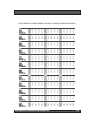
CONVERTING TEMPO (BPM) TO DELAY TIME (IN MILLISECONDS)
Tempo
Crotchet
Quaver
Semi-quaver
Dotted semi-quaver
Tempo
Crotchet
Quaver
Semi-quaver
Dotted semi-quaver
Tempo
Crotchet
Quaver
Semi-quaver
Dotted semi-quaver
Tempo
45
46
47
48
49
50
51
52
53
54
55
56
57
58
59
1333
667
333
444
1304
652
326
435
1277
638
319
426
1250
625
313
417
1224
612
306
408
1200
600
300
400
1176
588
294
392
1154
577
288
385
1132
566
283
377
1111
556
278
370
1091
545
273
364
1071
536
268
357
1053
526
263
351
1034
517
259
345
1017
508
254
339
60
61
62
63
64
65
66
67
68
69
70
71
72
73
74
1000
500
250
333
984
492
246
328
968
484
242
323
952
476
238
317
938
469
234
313
923
462
231
308
909
455
227
303
896
448
224
299
882
441
221
294
870
435
217
290
857
429
214
286
845
423
211
282
833
417
208
278
822
411
205
274
811
405
203
270
75
76
77
78
79
80
81
82
83
84
85
86
87
88
89
800
400
200
267
789
395
197
263
779
390
195
260
769
385
192
256
759
380
190
253
750
375
188
250
741
370
185
247
732
366
183
244
723
361
181
241
714
357
179
238
706
353
176
235
698
349
174
233
690
345
172
230
682
341
170
227
674
337
169
225
90
91
92
93
94
95
96
97
98
99
100
101
102
103
104
Crotchet
Quaver
Semi-quaver
Dotted semi-quaver
667
333
167
222
659
330
165
220
652
326
163
217
645
323
161
215
638
319
160
213
632
316
158
211
625
313
156
208
619
309
155
206
612
306
153
204
606
303
152
202
600
300
150
200
594
297
149
198
588
294
147
196
583
291
146
194
577
288
144
192
Tempo
105
106
107
108
109
110
111
112
113
114
115
116
117
118
119
Crotchet
Quaver
Semi-quaver
Dotted semi-quaver
571
286
143
190
566
283
142
189
561
280
140
187
556
278
139
185
550
275
138
183
545
273
136
182
541
270
135
180
536
268
134
179
531
265
133
177
526
263
132
175
522
261
130
174
517
259
129
172
513
256
128
171
508
254
127
169
504
252
126
168
Tempo
120
121
122
123
124
125
126
127
128
129
130
131
132
133
134
Crotchet
Quaver
Semi-quaver
Dotted semi-quaver
500
250
125
167
496
248
124
165
492
246
123
164
488
244
122
163
484
242
121
161
480
240
120
160
476
238
119
159
472
236
118
157
469
234
117
156
465
233
116
155
462
231
115
154
458
229
115
153
455
227
114
152
451
226
113
150
448
224
112
149
Tempo
135
136
137
138
139
140
141
142
143
144
145
146
147
148
149
Crotchet
Quaver
Semi-quaver
Dotted semi-quaver
444
222
111
148
441
221
110
147
438
219
109
146
435
217
109
145
432
216
108
144
429
214
107
143
426
213
106
142
423
211
106
141
420
210
105
140
417
208
104
139
414
207
103
138
411
205
103
137
408
204
102
136
405
203
101
135
403
201
101
134
Tempo
150
151
152
153
154
155
156
157
158
159
160
161
162
163
164
Crotchet
Quaver
Semi-quaver
Dotted semi-quaver
400
200
100
133
397
199
99
132
395
197
99
132
392
196
98
131
390
195
97
130
387
194
97
129
385
192
96
128
382
191
96
127
380
190
95
127
377
189
94
126
375
188
94
125
373
186
93
124
370
185
93
123
368
184
92
123
366
183
91
122
Tempo
165
166
167
168
169
170
171
172
173
174
175
176
177
178
179
Crotchet
Quaver
Semi-quaver
Dotted semi-quaver
364
182
91
121
361
181
90
120
359
180
90
120
357
179
89
119
355
178
89
118
353
176
88
118
351
175
88
117
349
174
87
116
347
173
87
116
345
172
86
115
343
171
86
114
341
170
85
114
339
169
85
113
337
169
84
112
335
168
84
112
Tempo
180
181
182
183
184
185
186
187
188
189
190
191
192
193
194
Crotchet
Quaver
Semi-quaver
Dotted semi-quaver
333
167
83
111
331
166
83
110
330
165
82
110
328
164
82
109
326
163
82
109
324
162
81
108
323
161
81
108
321
160
80
107
319
160
80
106
317
159
79
106
316
158
79
105
314
157
79
105
313
156
78
104
311
155
78
104
309
155
77
103
Tempo
195
196
197
198
199
200
201
202
203
204
205
206
207
208
209
Crotchet
Quaver
Semi-quaver
Dotted semi-quaver
308
154
77
103
306
153
77
102
305
152
76
102
303
152
76
101
302
151
75
101
300
150
75
100
299
149
75
100
297
149
74
99
296
148
74
99
294
147
74
98
293
146
73
98
291
146
73
97
290
145
72
97
288
144
72
96
287
144
72
96
Tempo
210
46
47
48
49
50
51
52
53
54
55
56
57
58
59
Crotchet
Quaver
Semi-quaver
Dotted semi-quaver
286
143
71
95
1304
652
326
435
1277
638
319
426
1250
625
313
417
1224
612
306
408
1200
600
300
400
1176
588
294
392
1154
577
288
385
1132
566
283
377
1111
556
278
370
1091
545
273
364
1071
536
268
357
1053
526
263
351
1034
517
259
345
1017
508
254
339
ANALOGUE SYSTEMS RS-INTEGRATOR
149
RS295
DELAY EXPANDER
The RS295 Delay Expander expands the facilities provides by the RS290 Sampler/
Delay. It has no functionality in isolation.
All information relating to the RS295 is contained in the chapter on the RS290.
150
ANALOGUE SYSTEMS RS-INTEGRATOR