1
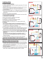
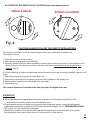
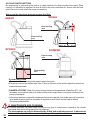
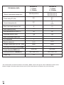
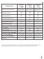
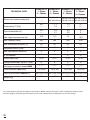
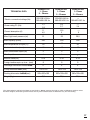
MIZAR
REGAL
SPRING
DUMPER
MANUALE D’ISTRUZIONI - Pag. 01
OPERATING INSTRUCTIONS - Page 20
BEDIENUNGSANWEISUNG
38
MANUALE
D’ISTRUZIONI- Seite
– PAG
MODE D’EMPLOI - Seite 56
MANUAL DE INSTRUCCIONES - Pag. 74
MANUAL DE INSTRUÇÕES - Pag 92
- 110
ARVEN s.r.l. via Artigiani n°10 25030
MACLODIO (Brescia) - ITALY
Tel. 030 9973973 - Fax 030 9973975
DECLARATION OF CONFORMITY
ISSUED ON NOVEMBER 20TH, 2013
The company ARVEN s.r.l. - via Artigiani, n°10 - 25030
MACLODIO (BS) - ITALY, under its own responsibility, declares that the pumps MIZAR, REGAL, SPRING, & DUMPER, are in accordance with the following directives:
-Directive on electromagnetic compatibility 2004/108/CE
and subsequent revisions.
-Directive on Low voltage 2006/95/CE and subsequent
revisions.
-Machines directive 2006/42/CE and subsequent
revisions.
-ROHS 2002/95/CE directive for the restrictions on the use of dangerous substances in electrical and electronical equipment.
20
Marcello Grazioli
Technical & Quality Dept.
ARVEN s.r.l.
INDEX
Pag.
1
GENERALS POINT
22
2
APPLICATIONS
PUMPED FLUIDS
22
3
4
5
5.1
5.2
6
6.1
6.2
6.3
6.4
6.5
7
7.1
7.2
7.3
8
8.4
9
TECHNICAL DATA AND USE LIMITATION
MANAGEMENT
Storage
Transport
WARNINGS
Qualified personnel
Safety
Motor shaft rotation check
Filter cleaning
Responsibility
INSTALLATION
Installation site Working conditions
Piping
ELECTRICAL CONNECTION: (8.1 - 8.2 - 8.3)
Checking the direction of rotation for three-phase motors
22
22
23
24 - 25
25 - 26
26 - 27
13
STARTING UP: (9.1)
Float switch regulating
PRECAUTIONS
MAINTENANCE AND CLEANING
MODIFICATIONS AND SPARE PARTS
TROUBLESHOOTING
29 - 30
14
TECHNICAL DATA
31 - 37
9.2
10
11
12
27 - 28
28
28 - 29
29
21
1 GENERAL POINTS
Read this documentation carefully before installation.
Installation and functioning must comply with local and national safety regulations in force in
the country where the product is to be installed.
The entire operation must be carried out in a workmanlike manner.
Failure to comply with the safety regulations not only causes risk to personal safety and damage to the equipment, but also invalidates any right to warranty assistance.
Keep this manual in a safe place for further consultation even after the first
installation.
2 APPLICATIONS
These electropumps (MIZAR, REGAL, SPRING, DUMPER) find use systems for lifting water
from wells, first collection tanks or cisterns, streams, particularly suited to construction work
site (only REGAL PROFESSIONAL & DUMPER), to basament pump out (cellar, garages), to
swimming pools pump out and small agricultural installations, sprinkling systems for gardens
and allotments. When installed in wells or tanks, the pump, which is particularly silent running,
avoids all problems related to suction and loss of priming.
The pump may be supplied with a float switch cutting out operation automatically in the event
of an insufficient water level.
These pumps cannot be used in swimming pools, ponds or tanks in which people are
present, or for pumping hydrocarbons (petrol, diesel fuel, fuel oils, solvents, etc.) in
accordance with the accident-prevention regulations in force.
N.B. : The liquid employed in the pump for lubricating the sealing device is not toxic, but it could alter the water properties (in the case of pure water) if there were any leaks in the seal.
3 PUMPED FLUIDS
The machine has been designed and built for pumping water, free from explosive substances,
and solid particles or fibres, with a density of 1 Kg/dm3 and a kinematic viscosity of 1mm2/s,
and chemically non-aggressive liquids.
4 TECHNICAL DATA AND USE LIMITATIONS
- Supply voltage:
- Absorbed power:
- Maximum ,working pressure:
- Pumped fluid:
- Degree of motor protection: - Thermal class:
- Liquid temperature range:
- Maximum immersion:
- Storage temperature:
- Noise level:
- Motor constructions:
22
see electric data plate
see electric data plate
2,6 Bar
clean (MIZAR), dirty, slyghtly sandy (REGAL)
IP 68
F
MIZAR, REGAL & SPRING: from 0°C to +35°C
DUMPER: from 0°C to 25°C part. submerged,
from 25°C to 35°C totally submerged.
5 metres
from -10°C to +40°C
noise level is contained within the limits envisaged by EC
Directive EC 89/392/CEE and subsequent modifications.
70 dB
in accordance with CEI 2-3 - CEI 61-69 (EN 60335-2-41)
standards.
5 MANAGEMENT
5.1. STORAGE
All the pumps must be stored indoors. in a dry. vibration-free and dust-free environment, possibly at constant air humidity.
They are supplied in their original packaging and must be kept there until installation.
5.2. TRANSPORT
Avoid subjecting the products to needless jolts or collisions.
The electropumps must never be carried or lifted by their power cables.
6 WARNINGS
6.1. QUALIFIED PERSONNEL
Installation should be performed by skilled and qualified personnel, in possession of the
technical qualifications required by the specific regulations in force.
The term qualified personnel means persons who, because of their training, experience and
regulations as well as all operating circumstances, have been entitled by the person responsible
for the system to work on and with the system and to see and avoid all possible dangers (Definition for technical personnel. (Definition for technical personnel IEC 364).
6.2. SAFETY
- Use is allowed only if the electric system is provided with safety precautions in accordance with the regulations in force in the country where the product is installed (for Italy, CEI 64/2).
- Never let the pump run dry.
- The pump cannot be used in swimmingpools, ponds or tanks in which people are present.
- The pump is provided with a handle to which a rope or cable may be connected to lower the machine into working position.
The pumps must never be carried, lifted or operated hanging from their power cables.
- Qualified personnel must be employed for all electrical repairs which, if badly carried out, could cause damage and accidents.
6.3. MOTOR SHAFT ROTATION CHECK
If the motor does not work and the shaft does not turn when the switch and/or float is operated, you must check that all working parts are turning freely.
To do this:
- Completely disconnect the pump from the mains.
- Place the pump in a horizontal position.
- Remove the grill and the diffuser, and operating on the self-loccking-nut with a fork wrench 13 (from 10 for only REGAL 30), rotate the shaft motor clockwise.
- Reassemble the grill and the conveyor and install the electropump as indicated in
chapter 7.
6.4. FILTER CLEANING (SPRING)
To clean the filter, proceed as follows:
- Completely disconnect the pump from the power mains.
- Place the pump in a horizontal position.
- Remove the grill.
- Clean the inside of the filter, removing any particles that may have been sucked in.
- Ensure that all filter slots are free from foreign bodies.
- Reassemble the grill and install the electropump as indicated in chapter 7.
23
6.5 RESPONSIBILITY
The Manufacturer does not vouch for the correct operation of the pumps and will not
be responsible for damages that might be caused by them, in case they are tampered
with or modified, run outside the recommended work range or in contrast with the
other instructions given in this manual.
The Manufacturer assumes no liability resulting from or omissions in this booklet, if
due to misprints or errors in copying. The company reserves the right to make modifications to the products described herein, when considered necessary or useful,
without changing the essential characteristics of the product itsef.
24
200 mm
OFF
REGAL
200 mm
5m
ON
immersion max
OFF
SPRING
250 mm
5m
ON
immersion max
OFF
DUMPER
5m
ON
immersion max
• This appliance is not intended for use by persons (including
children) with reduced physical, sensory or mental capabilities,
or lack experience and knowledge, unless they have been
given supervision or instruction.
• Children should be supervised to ensure that they do not play
with the appliance.
• The pump must be supplied through a residual current device
(RCD) with a rated residual operating current ≤ 30 Ma.
5m
INSTRUCTIONS FOR SAFE USE:
ON
immersion max
7.1 SITE OF INSTALLATION
• Pumps marked with maximum liquid temperature (°C) which
not less than 35 °C.
• Before immersing the electropump in the pit or tank, ensure
that the place is free from sand or solid sediment.
• In case there is sediment, accurately clean the site where it
is to be placed..
• Keep the pump at least 1 mt. raised above the bottom of the
pit so that any deposits that form after installation will not be
sucked up.
• Remove the sediment periodically.
• It is very important to ensure that the water level never falls
below the body of the pump.
7.2 WORKING CONDITIONS
• Pump body always completely immersed.
• The pump cannot operate dry.
• Installation in vertical or horizontal position.
• The housing pit must be frost-free.
• Maximum depth of immersion 5 mt. (below water level).
7.3 PIPING
• Put the pump into the liquid to be pumped (Inspect for the
max. pumping height, refer to the performance curve)
• The hydraulic connection of the pump may be made with iron
or plastic parts, either rigid or flexible.
• Avoid any kind of choking of the output pipe.
• It is advisable to use pipes with an internal diameter at least
equal to that of the delivery pipe, so as to avoid a fall in the
performance of the pump and the possibility of clogging.
• For the version with a float switch, ensure that the latter can
move freely (see Paragraph 9.2. “REGULATING THE FLOAT
SWITCH”).
The size of the pit must always be calculated in relation to
the quantity of incoming water and to the flow rate of
the pump so as not so subject the motor to an excessive
number of starts. • To lower the pump, always use a rope or chain fixed be
forehand to the upper handleo on top of the pump.
Never use the power cable to lift the electropump.
• When using in deep wells, it is advisable to secure the power
cable to the delivery pipe with clamps, every two/three metres.
MIZAR
300 mm
7 INSTALLATION
OFF
25
WARNING! The pump should not be run dry! It should be put fully into the liquid to be pumped.
Slurping for long periods should be avoided.
The length of the power cable on the electropump limits the maximum depth of immersion at
which the pump may be used.
8 ELECTRICAL CONNECTIONS
CAUTION! ALWAYS FOLLOW THE SAFETY REGULATIONS!
8.1 The electrical installation must be carried out by an authorized and competent electri
cian who assumes all the responsibilities.
8.2. Ensure that the mains voltage is the same as shown on the plate of the motor to be fed and be sure TO MAKE A GOOD GROUND CONNECTION.
8.3. The electropump, both the single-phase and the three-phase version is supplied with an electric cable. If the power cable is damaged in any way it must be replaced, not repaired.
• It is advisable to connect the pump to a dedicated power line.
• Upstream from the pump, fit a suitably sensitive magnetothermal differential switch.
• Switch off the power upstream from the system before making the electrical connection.
• Single-phase motors are provided with built-in thermal overload protection and may be con
nected directly to the mains.
Warning: If the motor is overloaded it stops automatically. Once it has cooled down it starts again automatically without requiring any manual intervention.
•Three-phase pumps must be protected with motor protectors suitably calibrated
according to the values on the data plate of the pump to be installed.
•Connect the pump cable to the electric panel, ensuring that the following parts
correspond:
SINGLE PHASE
Yellow-green
Brown
Blue LI
N
• Before making a test start, check the water level inside the well.
26
8.4 CHECKING THE DIRECTION OF ROTATION (for three-phase motors)
MIZAR & REGAL
SPRING & DUMPER
Fig. 2
CAUTION! ALWAYS FOLLOW THE SAFETY REGULATIONS
The direction of rotation must be checked each time a new installation is carried out.
Proceed as follows:
1. Place the pump on a flat surface;
2. Start the pump and stop it immediately;
3. Carefully observe the kick-back on starting, looking at the pump from above. If the direction of ro
tation is correct, the upper cap will turn counter-clockwise as indicated by the arrows in the
drawing (Fig. 2).
If it is not possible to check as described above because the pump is already installed, check as follows:
1. Start the pump and observe the water flow rate.
2. Stop the pump, switch off the power and invert two phases on the supply line.
3. Restart the pump and check the water flow rate again.
4. Stop the pump.
The correct direction of rotation is the one that gives the higher flow rate.
9 START-UP
9.1•Turn the differential magnetothermal switch upstream from the pump to position I (ON) and wait until the water comes out of the delivery pipe.
• If malfunctions are found, disconnect the pump from the power supply, turning the differential
magnetothermal switch to position 0 (OFF) and consult the chapter 13 on “TROUBLESHOOTING”.
• The pump may be started and stopped:
- Manually by means of the differential magnetothermal switch upstream from the system.
- Automatically when water level rises, for versions with a float switch.
27
9.2.FLOAT SWITCH SETTING
By lengthening or shortening the stretch of cable between the float and the fixed point (Float
locking) it is possible to regulate the level at which the pump switches off. Ensure that the float
witch can move freely when the pump is operating.
Make sure the stop level does not uncover the filter.
REGAL
MIZAR
Float locking
wire
Float locking
wire
SPRING
DUMPER
Float locking
wire
Float locking
wire
10 PRECAUTIONS
•The suction filter must always be present when during pump is operating.
•The pump must not be started more than 15 time in one hour so as not to subject the motor to ex cessive thermal stress.
•DANGER OF FROST: When the pump remains inactive at temperatures of less than 0°C, it is necessary to ensure that there is no water residue which might freeze, and cause cracking of the pump components.
• If the pump has been used with substances that tend to deposit, rinse it after use with a powerful jet of water so as to avoid the formation of deposits or scale which would, tend to reduce the pump characteristics.
11 MAINTENANCE AND CLEANING
28
In normal operation the pump does not require any type of maintenance, thanks to the oil bath
lubricated seal and to the greased-for-life bearings.
The electropump can only be dismantled by skilled and qualified personnel, in possession
of the technical qualifications required by the specific regulations in force.
In any case, all repair and maintenance jobs must be carried out only after having disconnected
the pump from the power mains, once made sure that it cannot suddenly begin working.During
dismantling it is necessary to pay great attention to sharp parts which may cause injury.The cutting edge flange of the electropump is provided of aspiration fans. It is advisable, every now and
then, to clean these fans to avoid a loss of efficiency. Best cleaning is obtained through a throw
of water. Sand and other abrasive materials cause precocious wear and tear, as well as loss of
performances.
12 MODIFICATIONS AND SPARE PARTS
Any modification not authorized beforehand relieves the manufacturer of all responsibility.
All the spare parts used in repairs must be original ARVEN. For codes and denominations see
enclosed sheet.
All accessories must be approved by the manufacturer so as to be able to ensure maximum
safety of the machines and systems in which they may be fitted.
13 TROUBLESHOOTING
FAULT
1.The motor does not start and makes no noise.
CHECK (possible cause)
A.Make sure motor is live and check that the mains voltage corresponds to the one on the data plate.
B.Check the protection fuses.
C.The float switch prevents
starup.
2.The pump does not deliver.
B. If they are burnt-out, change them.
C. Make sure float moves freely and check its efficiency.
D.The shaft is not turning.
D. Turn the shaft as indicated in the Warnings chapter
(Paragraph 6.3. ).
A.The suction filter or the pipes are obstructed.
A.Remove the obstructions, as indicated in the Warnings
chapter (Paragraph 6.4).
B.The impellers are worn or blo-
cked.
B.Change the impellers or remove the obstruction.
C.The fluid level is too low.On starting, the water level must be higher than the filter level.
C.Regulate the length of the float switch cable (See chap
ter on Warnings - Paragraph 9.2.)
D.The head required is higher than thepump’s characteristics
3.The pump does not stop.
REMEDY
A. The float does not interrupt the operating of the pump.
A. Make sure float moves freely and check its efficient.
29
FAULT
4.The flow rate is insufficient.
5.The overload protec
tion device stops the pump.
CHECK (Possible cause)
REMEDY
A .Ensure that the suction filter is not partlyblocked.
A.Remove any obstructions, as
indicated in the chapter on
Warnings (Paragraph 6.4.).
B. Ensure that the impellers or the delivery pipe are not partly
blocked or fouled with scale.
B. Check good operation of the
valve and replace it if necessary.
C. Ensure that the check valve (if fitted) is not partly clogged.
C. Accurately clean the check valve.
D. Check the direction of rotation
in three-phase versions (See
Chapter on Electrical connection - Paragraph 8.4.).
D. Invert two wires in the
power cable.
A.Ensure that the fluid to be pumped is not too dense
because it would cause overheating of the motor
B.Ensure that water temperature is not too high (see liquid tem
perature range).
B Reduce liquid temperature. Wait until thermal protection switch resets, about 20 mins.
C.The pump is partly blocked by impurities.
C. Accurately clean the pump.
D.The pump is mechanically
blocked.
D.Check for the occurrence of rubbing between moving and fixed parts; check the state of wear of the bearings (contact the supplier).
DON’T DISPOSE OF WORN-OUTS UNITS THROUGH THE
HOUSEHOLD GARBAGE
The appliance, its packaging and accessories are all produced from
recyclable materials and must be disposed of accordingly, in the suitable dispose places, adhering itself to the modalities previewed from the
enforced norms in matter
30
14 TECHNICAL DATA
MIZAR 60 VOX
1~ Phase
3 ~ Phases
MIZAR 30
1~ Phase
3 ~ Phases
MIZAR 60
1~ Phase
3 ~ Phases
220-230 V/50 Hz
---
220-230 V/50 Hz
380-400 V/50 Hz
220-230 V/50 Hz
380-400 V/50 Hz
Power rating P1 (Kw)
0,5
---
0.7
0.7
0.6
0,6
Current absorption (A)
2,2
---
3,0
1.4
2.8
1.3
8
10
7,5
Max. capacity (I/min)
150
175
175
Max temperature of liquid (°C)
50
50
50
Horizontal suction. (mm)
60
60
60
Max. submersion depth (mt)
30
30
50
N° of impellers
1
1
1
5 - 10
5 - 10
5 - 10
Foreign bodies aspir. up to ø... (mm)
10
10
20
Discharge connection thread DNM
1 1 / 4”
1 1 / 4”
1 1 / 4”
154 x 249
154 x 249
154 x 282
220 x 190 x 330
220 x 190 x 330
220 x 190 x 330
5,5
6,2
6,5
TECHNICAL DATA
Electric connection/voltage (Hz)
Max. High head pressure (mt)
Electric cable (mt)
Pump dimension BxD (mm)
Packing dimension LxMxN(mm)
Weight (Kg)
-The characteristics and technical data are not binding. Arven reserves the right to make modifications without notice.
Therefore weights, dimensions,performances and any other stated issues are indicative only and not binding
31
REGAL 80
1~ Phase
3 ~ Phases
REGAL 100
1~ Phase
3 ~ Phases
REGAL 150
1~ Phase
3 ~ Phases
220-230 V/50 Hz
380-400 V/50 Hz
220-230 V/50 Hz
380-400 V/50 Hz
220-230 V/50 Hz
380-400 V/50 Hz
Power rating P1 (Kw)
1.1
0.9
1.5
1,3
2,2
2
Current absorption (A)
4,5
2,1
6,5
2,2
10,6
3,3
Max. High head pressure (mt)
11,5
14,5
16,5
Max. capacity (I/min)
250
300
450
Max temperature of liquid (°C)
50
50
50
Horizontal suction. (mm)
35
35
35
Max. submersion depth (mt)
5
5
5
N° of impellers
1
1
1
5-10
5-10
5-10
Foreign bodies aspir. up to ø... (mm)
10
10
10
Discharge connection thread DNM
1” 1 / 2
1” 1 / 2
2”
212,4 x 290,2
212,4 x 290,2
212,4 x 326,7
220 x 320 x 340
220 x 320 x 340
250 x 290 x 460
9
11
18
TECHNICAL DATA
Electric connection/voltage (Hz)
Electric cable (mt)
Pump dimension BxD (mm)
Packing dimension LxMxN(mm)
Weight (Kg)
-The characteristics and technical data are not binding. Arven reserves the right to make modifications without notice.
Therefore weights, dimensions,performances and any other stated issues are indicative only and not binding
32
REGAL 100 VOX
1~ Phase
3 ~ Phases
REGAL 150 VOX
1~ Phase
3 ~ Phases
REGAL 200 VOX
1~ Phase
3 ~ Phases
220-230 V/50 Hz
380-400 V/50 Hz
220-230 V/50 Hz
380-400 V/50 Hz
--380-400 V/50 Hz
Power rating P1 (Kw)
1,5
1,5
2,2
2
--2,2
Current absorption (A)
6,8
2,4
9
3,3
--3,8
Max. High head pressure (mt)
10,5
12,5
14
Max. capacity (I/min)
350
400
450
Max temperature of liquid (°C)
50
50
50
Horizontal suction. (mm)
35
35
35
Max. submersion depth (mt)
5
5
5
N° of impellers
1
1
1
5-10
5-10
5-10
Foreign bodies aspir. up to ø... (mm)
30
30
30
Discharge connection thread DNM
1 1 / 2”
2”
2”
204 x 344,2
204 x 384,7
204 x 384,7
260 x 320 x 480
260 x 380 x 480
260 x 320 x 480
13
20
21
TECHNICAL DATA
Electric connection/voltage (Hz)
Electric cable (mt)
Pump dimension BxD (mm)
Packing dimension LxMxN(mm)
Weight (Kg)
-The characteristics and technical data are not binding. Arven reserves the right to make modifications without notice.
Therefore weights, dimensions,performances and any other stated issues are indicative only and not binding
33
TECHNICAL DATA
SPRING 30
1~ Phase
3 ~ Phases
SPRING 60
1~ Phase
3 ~ Phases
220-230 V/50 Hz
---
220-230 V/50 Hz
380-400 V/50 Hz
Power rating P1 (Kw)
0.5
---
0.7
0,7
Current absorption (A)
2,2
---
3
3,14
8
10
Max. capacity (I/min)
150
175
Max temperature of liquid (°C)
50
50
Horizontal suction. (mm)
136
136
Max. submersion depth (mt)
5
5
N° of impellers
1
1
Electric cable (mt)
5-10
5-10
Foreign bodies aspir. up to ø... (mm)
clean
clean
Discharge connection thread DNM
1 1 / 4”
1 1 / 4”
154 x 342
154 x 342
190 x 230 x 410
190 x 230 x 410
5,5
6,2
6,5
Electric connection/voltage (Hz)
Max. High head pressure (mt)
Pump dimension BxD (mm)
Packing dimension LxMxN(mm)
Weight (Kg)
-The characteristics and technical data are not binding. Arven reserves the right to make modifications without notice.
Therefore weights, dimensions,performances and any other stated issues are indicative only and not binding
34
SPRING 80
1~ Phase
3 ~ Phases
SPRING 100
1~ Phase
3 ~ Phases
SPRING 150
1~ Phase
3 ~ Phases
220-230 V/50 Hz
380-400 V/50 Hz
220-230 V/50 Hz
380-400 V/50 Hz
220-230 V/50 Hz
380-400 V/50 Hz
Power rating P1 (Kw)
1.1
0,9
1,5
1,3
2
1,8
Current absorption (A)
4,5
2,1
6,5
2,2
10,6
3,3
Max. High head pressure (mt)
11,5
14,5
16,5
Max. capacity (I/min)
250
300
400
Max temperature of liquid (°C)
50
50
50
Horizontal suction. (mm)
160
160
160
Max. submersion depth (mt)
5
5
5
N° of impellers
1
1
1
Electric cable (mt)
5-10
5-10
5-10
Foreign bodies aspir. up to ø... (mm)
clean
clean
clean
Discharge connection thread DNM
1 1 / 2”
1 1 / 2”
2”
212,4 x 400
212,4 x 400
212,4 x 440,2
260 x 300 x 530
260 x 300 x 530
260 x 300 x 530
9
11
18
TECHNICAL DATA
Electric connection/voltage (Hz)
Pump dimension BxD (mm)
Packing dimension LxMxN(mm)
Weight (Kg)
-The characteristics and technical data are not binding. Arven reserves the right to make modifications without notice.
Therefore weights, dimensions,performances and any other stated issues are indicative only and not binding
35
TECHNICAL DATA
Electric connection/voltage (Hz)
DUMPER 70
1~ Phase
3 ~ Phases
DUMPER 80
1~ Phase
3 ~ Phases
DUMPER 100 DUMPER 140
1~ Phase
1~ Phase
3 ~ Phases
3 ~ Phases
220-230 V/50 Hz 220-230 V/50 Hz 220-230 V/50 Hz 220-230 V/50 Hz
380-400 V/50 Hz 380-400 V/50 Hz 380-400 V/50 Hz
---
Power rating P1 (Kw)
0,9
---
1,1
1,0
1,3
1,1
2
1,7
Current absorption (A)
4,5
---
4,5
2,1
6,5
2,6
9
3
Max. High head pressure (mt)
10,5
11,5
15
19,5
Max. capacity (I/min)
200
250
300
400
Max temperature of liquid (°C)
50
50
50
50
Horizontal suction. (mm)
40
40
40
40
Max. submersion depth (mt)
5
5
5
5
N° of impellers
1
1
4
6
5-10
5-10
5-10
5-10
Foreign bodies aspir. up to ø... (mm)
8
8
8
8
Discharge connection thread DNM
1 1 / 2”
1 1 / 2”
1 1 / 2”
1 1 / 2”
142 x 300
142 x 300
142 x 300
142 x 344
Electric cable (mt)
Pump dimension BxD (mm)
Packing dimension LxMxN(mm)
Weight (Kg)
190 x 220 x 320 190 x 220 x 320 190 x 220 x 320 190 x 320 x 340
13
13
13,5
18,5
-The characteristics and technical data are not binding. Arven reserves the right to make modifications without notice.
Therefore weights, dimensions,performances and any other stated issues are indicative only and not binding
36
TECHNICAL DATA
DUMPER 150
1~ Phase
3 ~ Phases
DUMPER 200
1~ Phase
3 ~ Phases
DUMPER 300
1~ Phase
3 ~ Phases
220-230 V/50 Hz
380-400 V/50 Hz
220-230 V/50 Hz
380-400 V/50 Hz
--380-400 V/50 Hz
Power rating P1 (Kw)
2,7
2,5
2.9
2.7
--3.4
Current absorption (A)
11
4,5
12,5
5
--6
Max. High head pressure (mt)
21
23
26,5
Max. capacity (I/min)
350
400
500
Max temperature of liquid (°C)
50
50
50
Horizontal suction. (mm)
40
40
40
Max. submersion depth (mt)
5
5
5
N° of impellers
1
1
1
5-10
5-10
5-10
Foreign bodies aspir. up to ø... (mm)
8
8
8
Discharge connection thread DNM
2”
2”
2”
190 x 378
190 x 378
190 x 378
260 x 300 x 530
260 x 300 x 530
260 x 300 x 530
26,5
28,5
29,5
Electric connection/voltage (Hz)
Electric cable (mt)
Pump dimension BxD (mm)
Packing dimension LxMxN(mm)
Weight (Kg)
-The characteristics and technical data are not binding. Arven reserves the right to make modifications without notice.
Therefore weights, dimensions,performances and any other stated issues are indicative only and not binding
37
ARVEN S.r.l.
Via Artigiani n°10
25030 Maclodio - Brescia Italy
Tel. +39.030.9973973
Fax +39.030.9973975
e-mail: [email protected]
www.arven.it