1
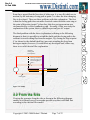
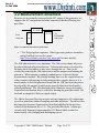
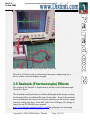
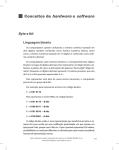
Rev 1.4
14 Feb 2004
The World Leader in Electromagnetic Physics
Paradox 2 Experiment
By Robert J Distinti B.S. EE
46 Rutland Ave.
Fairfield Ct 06825.
(203) 331-9696
AAbbssttrraacctt
The Paradox 2 experiment is a simple device which develops both AC and DC electric
power in a manner not described by accepted (classical) magnetic flux theory (hence the
name Paradox). Essentially, this device generates electric power while the number of flux
lines contained in (linked by) each conductive loop remains constant.
This experiment demonstrates only one of many anomalies and paradoxes of classical
electromagnetic theory. For a complete list see http://www.distinti.com/docs/apoce.pdf
Note: this is not free-energy or over-unity; just an exploratory experiment of the laws of
physics.
Copyright © 2003-2004 Robert J Distinti.
Page 1 of 22
Rev 1.4
14 Feb 2004
The World Leader in Electromagnetic Physics
1 THE PARADOX 2 ..................................................................................... 3
1.1 DESCRIPTION OF THE PARADOX 2............................................................ 4
2 ANALYSIS USING CLASSICAL THEORY ......................................... 6
2.1 FROM THE TOP ........................................................................................ 6
2.2 FROM THE SIDE ....................................................................................... 7
2.3 CONCLUSION OF CLASSICAL ANALYSIS................................................... 8
3 PRIOR TO TESTING ............................................................................... 9
3.1 SIMPLIFIED WIRING FROM PREVIOUS........................................................ 9
3.2 MEASUREMENT ENSEMBLE .................................................................... 10
3.3 DVMX1000 .......................................................................................... 11
3.4 MICROVOLTS?....................................................................................... 11
3.5 SEEBECK (THERMOCOUPLE) EFFECTS ................................................... 12
3.6 GREASE ................................................................................................. 13
4 TESTS PERFORMED ............................................................................ 14
4.1 NO MAGNETS—NO POWER .................................................................... 14
4.2 OPPOSING MAGNETS—POWER ............................................................... 14
4.3 BOTH MAGNETS NORTH-FACE-UP —ESSENTIALLY NO POWER............... 15
4.4 ONE MAGNET – HALF POWER ................................................................. 16
4.5 FUTURE TESTS ....................................................................................... 18
5 CONCLUSION ........................................................................................ 19
APPENDIX A. CONSTRUCTION NOTES .......................................... 20
A.1. MAGNET/ROTOR SIZE RELATION ........................................................ 20
APPENDIX B. NEW ELECTROMAGNETISM.................................. 21
A.2. FROM THE TOP .................................................................................... 21
A.3. FROM THE SIDE ................................................................................... 21
APPENDIX C. DOCUMENT HISTORY .............................................. 22
Copyright © 2003-2004 Robert J Distinti.
Page 2 of 22
Rev 1.4
14 Feb 2004
The World Leader in Electromagnetic Physics
1 The Paradox 2
The following photo is a close-up of the Paradox 2 experiment. For MPEGs
of the device in operation and schedule of public demonstrations, go to
http://www.distinti.com/paradox .
Figure 1-1: Close-up of completed Paradox 2 Generator
Output measurement ensemble.
Connected by brushes across lower
and upper shafts. Includes Low
pass filter and micro-volt sensitive
measuring instrumentation.
Upper brass shaft – electrically
isolated from lower shaft and
electrically connected to north
side brush assembly
Disk magnet, South side up
South side brush assembly, moves
with armature and makes contact
with stationary copper ring and is
electrically connected to lower
brass shaft.
S
Stationary
copper ring
V
N
Disk magnet, North side up
North side brush assembly, moves
with armature and makes contact
with stationary copper ring
Lower Shaft. Electrically isolated
from upper shaft and connected to
south side brush assembly
Figure 1-2: Schematic of Paradox 2 Generator
Copyright © 2003-2004 Robert J Distinti.
Page 3 of 22
Rev 1.4
14 Feb 2004
The World Leader in Electromagnetic Physics
1.1 Description of the Paradox 2
Note: Although this generator develops both AC and DC power; our
primary interest (in all experiments) is the DC power. Our discussion
of the AC components is provided only for completeness.
The Paradox 2 generator consists of a rotating element (the rotor) and a
stationary element (called the stator). The rotor consists of a plywood disk
into which two disk magnets are embedded. One magnet is North-face-up
and the other South-face-up. The rotor is suspended by two brass shafts (the
upper and lower) which are electrically isolated from each other. The upper
shaft is electrically connected to a brush assembly which brings current from
the shaft out across the North-face-up magnet (see Figure 3-1) and deposits
it on a stationary copper ring which forms part of the stator. The rotor
contains another brush assembly which picks current up from the opposite
side of the stationary ring and brings it across the South-face-up magnet and
down (through a wire) to the lower shaft where it is allowed to exit. The
following photo (Figure 1-3) shows the stationary copper ring and the center
conductive socket which mechanically and electrically contacts the lower
shaft.
Figure 1-3: Detail showing armature removed
Copyright © 2003-2004 Robert J Distinti.
Page 4 of 22
Rev 1.4
14 Feb 2004
The World Leader in Electromagnetic Physics
The generator disk is driven by a toy motor gear box as shown in the
following photo. The blue and red wires run across the top to a 6 Volt dry
cell at the right. The capacitor soldered across the terminal lugs helps reduce
high frequency brush noise. The capacitor shown is .68uf Polypropylene.
The motor is electrically isolated from the drive shaft by plastic gears.
Consequently, there is no significant electromagnetic coupling between the
motor circuit and the generator circuit. This is verified by the first test
where the generator is run without magnets and no power is detected at the
output (see section 4.1). If there were coupling of energy from the motor
circuit (or any other extraneous source) then the test run without magnets
would show a non-zero signal.
Copyright © 2003-2004 Robert J Distinti.
Page 5 of 22
Rev 1.4
14 Feb 2004
The World Leader in Electromagnetic Physics
2 Analysis using classical theory
Since all models of electromagnetism (both New and Classical) are linear,
then it is simpler to break up the analysis into separate parts and then sum
the separate parts together. This is called superposition.
Note: Although this generator develops both AC and DC power; our
primary interest (in all experiments) is the DC power. Our discussion
of the AC components is provided only for completeness.
2.1 From the Top
Direction of
rotation
Area A
N
Closing path
These elements
rotate together
V
Point C
S
Area B
Figure 2-1: Top Schematic view of generator in operation
When the device is rotating counter clockwise, charges are moved in the
direction shown by the blue arrows in the above diagram.
If we ignore the closing path for a moment, it is clear that the areas that link
the magnetic flux lines (Area A and Area B) always move with the magnets;
therefore, there can not be flux lines entering or exiting and therefore no flux
lines are being cut.
Secondly, the total flux contained in areas A and B is the sum of two
opposing magnets; therefore, no net flux is contained in either Area A or
Area B.
Copyright © 2003-2004 Robert J Distinti.
Page 6 of 22
Rev 1.4
14 Feb 2004
The World Leader in Electromagnetic Physics
Some have argued that the bisection of either area A or area B (which are in
motion) by the stationary closing path at point C is where the time changing
flux is developed. There are three problems with this explanation. The first
is that the closing path does not make electrical contact with the outer ring at
the point of bisection (point C); therefore, this does not represent an area
circumscribed by a closed conductive path. Secondly, if this were truly the
explanation of the system, then we should expect only an AC output.
The third problem with the above explanation (referring to the following
diagram) is that it is possible to extend the shafts and the closing path to the
extremes to avoid cutting flux from the magnet. By closing the loop at point
C (as shown by the dashed black line) prevents extending the loop from
having an impact; however, it would short any developed emf; either way,
there is no valid classical flux explanation.
Alternate
closing path
brush position
Missing connection
between copper ring
and closing path at
point C
N
S
V
Closing path
Figure 2-2: Thirdly
2.2 From the Side
Viewing the generator from the side as shown in the following diagram,
enables us to identify area D as another possible area that could link flux
according to the classical flux model.
Copyright © 2003-2004 Robert J Distinti.
Page 7 of 22
Rev 1.4
14 Feb 2004
The World Leader in Electromagnetic Physics
Area D
N
S
V
Closing path
Figure 2-3: Paradox Generator: Schematic side view
Because the ring is stationary and the magnets move symmetrically with
respect to it, there is no flux cut by the ring; consequently, because the
armature brush assemblies move with the magnets, they too do not cut flux;
therefore, we can redraw the above into the following electrical equivalent:
Area D
A single flux line
N
S
V
Closing path
Figure 2-4: Side View: Simplification
From the standpoint of classical theory, as a magnet passes through area D,
flux lines are indeed cut as shown in Figure 2-4; however, the number of
exiting flux lines that are cut equals the number of entering flux lines that
are cut; therefore, there is no net flux cut, and consequently no net emf
predicted by classical theory.
2.3 Conclusion of Classical Analysis
It may be possible to explain A.C. signals developed from this device using
classical field theory; however, there seems to be no way of anticipating DC
power. This is why we focus on the DC output of the device.
In the experimental tests, we apply a low pass filter to suppress A.C.
(transient) signal components.
Copyright © 2003-2004 Robert J Distinti.
Page 8 of 22
Rev 1.4
14 Feb 2004
The World Leader in Electromagnetic Physics
3 Prior to Testing
3.1 Simplified wiring from previous
The following photo shows a close-up of the brush circuit to show that it
matches the diagrams. In the previous photos (from version 1.0 of this
document), there were superfluous red and green wire loops that carried the
current from the shafts to points on the brushes farther to the outside. The
red and green wire loops were intended to provide slack when moving the
brush assembly out of the way for changing out the magnets.
Figure 3-1: Armature Brush wiring close-up
Although the presence of the loops does not affect the outcome of the
experiment, they were removed and the brushes connected to the shafts as
shown above to ensure that the presence of the loops does not cause
confusion. All tests are run on the above configuration.
Copyright © 2003-2004 Robert J Distinti.
Page 9 of 22
Rev 1.4
14 Feb 2004
The World Leader in Electromagnetic Physics
3.2 Measurement ensemble
Because we are primarily interested in the DC output of this generator, we
suppress the AC components and other transients with the following low
pass filter.
R=470K
From
Generator
R=
10K
C=0.33uF
*
To
DVMx1000
and scope
Figure 3-2: 10K load and 1 Hertz Low Pass filter
• * Use Polypropylene capacitor. Other types may produce anomalous
energy build-up (see our free paper
http://www.distinti.com/docs/cap_anom.pdf for more details).
The 10K ohm resistor is very important. The 10k resistor shunts all power
developed through triboelectrification. Triboelectrification is developed by
the brass brush assemblies as they move through the air. This can be
verified by removing the 10k ohm resistor and the magnets and running the
generator. When running, seemingly random power is detected by the
measurement ensemble. By placing masking tape over the exposed brass to
reduce contact with moving air helps mitigate these signals; however, it is
much simpler to load the generator down with the 10K load since the power
developed by the magnets is much more powerful than that developed by
triboelectrification. The 10k ohm load easily shunts the energy developed
from triboelectrification; this is verified by running the generator with a 10k
load and no magnets to show no signal output.
The 1Hertz low pass filter (top resistor and cap) suppresses AC components
as well as power-line induced coupling and other transients. The above filter
has improved response characteristics than that published in the previous
release of this document (Rev 1.0). The previous filter had a 1 radian per
second cutoff frequency (approximately 0.16 Hertz) which resulted in
unnecessarily slow charging and discharging curves.
Copyright © 2003-2004 Robert J Distinti.
Page 10 of 22
Rev 1.4
14 Feb 2004
The World Leader in Electromagnetic Physics
3.3 DVMx1000
Because the DVMx1000 has a gain of 1000, the vertical scope sensitivity is
actually 100 microvolts per division instead of 100 millivolts per division
shown in the screen captures. 100 microvolts per division is the vertical
sensitivity used in all tests except where specified.
The DVMx1000 is a chopper-stabilized amplifier has an input offset of less
than 2uV (0.5uV Typical). The DVMx1000 is used as the front end into the
scope. The DVMx1000 has a second order roll-off for frequencies above
300 hertz.
See the DVMx1000 user’s manual for more details
http://www.distinti.com/docs/ee001_m.pdf
3.4 Microvolts?
Some may argue that 100 microvolts is too small to be of consequence;
however, the following photo (Figure 3-3) shows that it is the proper scale
for the experiment. (Note: the horizontal setting is 1 second per division).
The scope shows a 10 second recording of the voltage induced in the twoturn loop of red wire by randomly moving the disk magnet about the loop.
The disk magnet used is identical to the ones used in the Paradox 2. The
resultant displacements, shown on the screen capture, are in the same range
(100 microvolts division) as that developed by the Paradox 2.
The Paradox 2 tests are in Section 4.
Copyright © 2003-2004 Robert J Distinti.
Page 11 of 22
Rev 1.4
14 Feb 2004
The World Leader in Electromagnetic Physics
Figure 3-3 Effect of randomly moving a magnet about a loop of wire
Therefore, 100 microvolts per division is the proper output range for a
device of this scale and magnet strength.
3.5 Seebeck (Thermocouple) Effects
The output of the Paradox 2 Experiment is not the result of thermocouple
(Seebeck) effects.
The dissimilar metal junctions are balanced throughout the design causing
the thermal offsets to substantially cancel each other. Even if the junctions
were not balanced, the worst case Seebeck junctions are the brass to copper
junctions which only have about 8uV offsets for a 20degree (F) change in
temp (see our DVMx1000 users manual
http://www.distinti.com/docs/ee001_m.pdf for techniques of measuring
Copyright © 2003-2004 Robert J Distinti.
Page 12 of 22
Rev 1.4
14 Feb 2004
The World Leader in Electromagnetic Physics
Seebeck effects). These 8uV offsets are far below the 150uV output of the
device (see tests in next section)
It is illogical for Seebeck effects to account for the output of the device since
Seebeck voltages are not dependant on magnetism. As such the device
would have an output even when operated without magnets. Furthermore,
the output would persist for a time after the device is turned off as the
junctions cool. Finally, the Seebeck junctions do not change direction when
the device is operated in reverse; as such, the output polarity would not
change if the device were operated in reverse.
The tests performed in section 4 clearly show substantially zero output when
the device is off or operated without magnets installed. When magnets are
installed, the output power is proportional to speed and direction of spin.
This device can not be explained away by Seebeck effects.
3.6 Grease
In order to reduce friction and enhance conductivity at the 4 brush positions,
a grease was concocted by combining graphite powder and household motor
oil (like 3 in 1 brand). This grease is what caused the prototype to become
sooty and grungy in the following photos.
Copyright © 2003-2004 Robert J Distinti.
Page 13 of 22
Rev 1.4
14 Feb 2004
The World Leader in Electromagnetic Physics
4 Tests Performed
4.1 No magnets—no power
When the magnets are removed; no power is developed.
This test verifies that the generator does not produce power from
unintentional effects (such as Seebeck, thermoelectric (thermocouple),
triboelectric, RF coupling, etc. etc.). See the mpeg movie
pdx2_no_mags.mpeg to watch the “magnet-less” generator produce no
power.
4.2 Opposing magnets—power
The normal configuration of this generator has one magnet North-face-up
and the other magnet South-face-up.
Copyright © 2003-2004 Robert J Distinti.
Page 14 of 22
Rev 1.4
14 Feb 2004
The World Leader in Electromagnetic Physics
The following scope capture shows the generator run in one direction for 4
seconds and then run in reverse for 4 seconds (approx). The MPEG movie
(pdx2.mpeg) which shows the actual test that this trace was taken from can
be downloaded from the Paradox2 generator page
http://www.distinti.com/paradox .
4.3 Both magnets North-face-up —
essentially no power
Copyright © 2003-2004 Robert J Distinti.
Page 15 of 22
Rev 1.4
14 Feb 2004
The World Leader in Electromagnetic Physics
This test produced minimal deflection which only shows that the magnets
are not perfectly equal in strength or position. If magnets were identical in
strength and the machining of the generator were perfect then equal and
opposite emfs would be induced in the device and no NET power detected at
the output. This is as predicted by New Electromagnetism.
Note: We are using double the vertical sensitivity (50uV per division)
than previous tests in order to enhance the minimal deflection of the
trace.
In the first four divisions of the scope screen capture shown above, the
generator is run forward; in the next four divisions, the generator is run in
reverse and then the generator is off for the last two divisions. It is plainly
visible that there is minimal trace deflection. For all intents and purposes,
there is no power generated in this configuration.
4.4 One magnet – half power
If the magnets were perfectly equal in strength and the device perfectly
machined, then removing one magnet will result in half the voltage output
(with everything else being equal).
Copyright © 2003-2004 Robert J Distinti.
Page 16 of 22
Rev 1.4
14 Feb 2004
The World Leader in Electromagnetic Physics
The following measurements were taken to test the one magnet operation of
the Paradox 2:
1. Both magnets = 180uV approx.
2. North magnet only =20 uV approx. – retarded spin (see following text)
3. South magnet only = 90uV approx.
4. North magnet in South hole = 80uV approx.
When the generator is run with only the North magnet installed (case 2
above), the weight imbalance of the rotor causes it grind against the stator.
This grinding phenomenon causes the loss of rpm and consequently output
voltage as shown in the measured results.
The above photo shows that the rotor, near the North magnet hole, only
clears stator by about a 64th of inch (for reference, magnets are 1.125 inches
in diameter).
By running either magnet out of the South Hole (cases 3 and 4 above)
resolves the problem since the South side of the rotor provides more
clearance. The clearance of the South side of the rotor is shown in the next
photo.
Copyright © 2003-2004 Robert J Distinti.
Page 17 of 22
Rev 1.4
14 Feb 2004
The World Leader in Electromagnetic Physics
The above photo shows that the rotor on the South side has more clearance.
Therefore, this side is more forgiving when run out of balance.
Operating the generator with either magnet in the South hole (cases 3 and 4
above) produces substantially half the normal output voltage output (case 1).
As stated previously, if the magnets where perfectly equal, and the
experiment perfectly machined, then running with one magnet will produce
half the output (with everything else being equal).
4.5 Future tests
We are improving our magnetic rotations modeling software (see
mag_rot_man.pdf) to model complex systems such as this. Once this
improvement is complete, we intended to use the software to design an
optimized and more accurately machined version in which more precise
measurements will be afforded.
Copyright © 2003-2004 Robert J Distinti.
Page 18 of 22
Rev 1.4
14 Feb 2004
The World Leader in Electromagnetic Physics
5 Conclusion
As demonstrated in preceding sections, classical magnetic flux theory
provides no practical explanation for the output of this generator (either AC
or DC). Power is predicted in classical flux theory when a conducting
material (such as copper) “cuts” or “links” flux lines. The Paradox 2
Generator develops both DC and AC electric power while the number of
flux lines linked remains constant in all cases. This experiment clearly
shows that classical electromagnetic theory is not a complete description of
electromagnetic interactions. (We have many free publications available
which demonstrate other mismatches between Mother Nature and
classical electromagnetic theory -- see the publications link at our site).
Another purpose of this experiment is to pry classical physics out of the
infinite loop it has been stuck in over the Homopolar Paradox (see
http://www.distinti.com/docs/homopolar.pdf). The Homopolar Paradox has
been “kicked” around for about 200 years. In order to resolve the paradox,
researchers have tried to answer the questions of whether the flux rotates
with the magnet or not. Proponents of the rotating field suggest that energy
is developed as the field is “cut” by the stationary closing path while others
propose that the energy is developed in the disk which means that the field
can not be rotating. New Electromagnetism (Specifically New Magnetism)
teaches that the above question is moot since the field does rotate; however,
no energy is developed in the closing path. This sounds like a contradictory
statement to classically trained scientists and engineers; however, the
Paradox 2 experiment clearly shows that power can be developed without
cutting flux lines.
Finally, it has been our experience that classical flux theory is so confusing
that many researchers do not know how to apply it properly (see
http://www.distinti.com/docs/coax_bar_mag.pdf for a common example).
This is why www.Distinti.com is the world leader in electromagnetic
physics.
Copyright © 2003-2004 Robert J Distinti.
Page 19 of 22
Rev 1.4
14 Feb 2004
The World Leader in Electromagnetic Physics
A
Appppeennddiixx A
A.. C
Coonnssttrruuccttiioonn N
Nootteess
These notes are for people who intend to build their own Paradox Generator.
We will offer optimized kits and plans in the near future.
The following construction tips will ensure success
A.1 Magnet/Rotor Size Relation
When we have completed the software modeling we will freely publish
optimized disk/magnet size relationships.
In the mean time, we recommend:
If you plan to use magnets with holes, ensure the diameter of the rotor is at
least three times the diameter of the magnets.
If you plan to use solid disk magnets, ensure the diameter of the rotor is at
least 4 times the diameter of the magnets.
Copyright © 2003-2004 Robert J Distinti.
Page 20 of 22
Rev 1.4
14 Feb 2004
The World Leader in Electromagnetic Physics
A
Appppeennddiixx B
B.. N
Neew
wE
Elleeccttrroom
maaggnneettiissm
m
This section moved to an appendix to keep it from frightening away people
too soon.
A.2 From the Top
New Magnetism applied to analysis of the top view predicts DC power as
shown in the experimental demonstrations. Those people who have
purchased the Engineer’s Edition of New Magnetism (BK001) will get full
details published in the online support areas in the days and weeks to come.
Also to be included is proprietary software packages which allow complex
analysis of magnetic systems in motion.
A.3 From the Side
New Magnetism predicts AC transients developed as the magnets pass into,
and consequently out of, Area D. These transients are cancelled by ensuring
that the magnets pass equidistant from the top and bottom of the closing
paths. Since we are more interested in the DC output of this device, the
paths were adjusted to minimize AC components.
Again, full disclosure of how to apply New Magnetism for these results is
only available to purchasers of the Engineer’s Edition of New Magnetism
(BK001).
Copyright © 2003-2004 Robert J Distinti.
Page 21 of 22
Rev 1.4
14 Feb 2004
The World Leader in Electromagnetic Physics
A
Appppeennddiixx C
C.. D
Dooccuum
meenntt H
Hiissttoorryy
Document History:
1.0 Initial release
1.1 Improved response of filter from 1 rad/sec to 1 cycle/sec and re-shot all
pertinent photos and movies. Other typographical and grammar fixes
1.2 Simplified abstract so as not to scare people away. It’s not a good idea
to beat up on the sacred cows or beat the New Electromagnetism drum until
after they see the experiment; moved New Electromagnetic discussion to
appendix for same reason. Added chapter with test conducted using single
magnet.
1.3 Added Seebeck effects discussion section (3.5)
1.4 Added details about how generator is driven.
Copyright © 2003-2004 Robert J Distinti.
Page 22 of 22