1
FINAL PROJECT
User Interface for communication through
CAN-Bus
Student:
Eduardo Fernández- Cantalejo Padial
Bearbeitungsbeginn:
01.05.2004
Abgabetermin:
30.09.2004
Belegscheinnummer:
2067
FINAL PROJECT
User Interface for communication through
CAN-Bus
Student:
Eduardo Fernández- Cantalejo Padial
Betreuer in München:
Prof. Dr. Höger/ Prof. Dr. Sommer
Betreuer in Sevilla:
Prof Dr. Rodríguez Rubio
Bearbeitungsbeginn:
01.05.2004
Abgabetermin:
30.09.2004
Belegscheinnummer:
2067
Fachhochschule München
Fachbereich Elektrotechnik und Informationstechnik
Erklärungen des Diplomanden:
Fernández Cantalejo Padial
Eduardo
Name
Vorname
1) Ich erkläre hiermit, daß ich die vorliegende Diplomarbeit selbständig verfaßt
und noch nicht anderweitig zu Prüfungszwecken vorgelegt habe.
Sämtliche benutzte Quellen und Hilfsmittel sind angegeben, wörtliche und
sinngemäße Zitate sind als solche gekennzeichnet.
Sevilla, 30. 09. 2004
Ort, Datum
Unterschrift
2) Ich erkläre mein Einverständnis, daß die von mir erstellte Diplomarbeit in die
Bibliothek der Fachhochschule München eingestellt wird. Ich wurde darauf
hingewiesen, daß die Fachhochschule in keiner Weise für die mißbräuchliche
Verwendung von Inhalten durch Dritte infolge der Lektüre der Arbeit haftet.
Insbesondere ist mir bewußt, daß ich für die Anmeldung von Patenten,
Warenzeichen oder Geschmacksmuster selbst verantwortlich bin und daraus
resultierende Ansprüche selbst verfolgen muß.
Ort, Datum
Unterschrift
Diplomarbeit
Abgabedatum:
30.09.2004
Betreuer:
Studierender:
Studiengruppe:
Prof. Dr. Höger
Prof. Dr. Sommer
Prof. Dr. Rodríguez Rubio
Thema:
Eduardo Fernández Cantalejo Padial
04EI5SOC
CAN-basierte Benutzeroberfläsche für Versuchstand
(User Interface for communication through CAN-Bus applied to practical classes)
Kurzfassung:
A SCADA System has been implemented. The objective is to get ready the
communication between a PC, which performs the function of Master, and several
motors. These devices have to be waiting for request from the PC to answer them.
They have no iniciative. The communication happens through a CAN Bus. Moreover,
the operative system of the motors is not a standard but OS/9000.
On the other hand, a user interface in the PC side has been programmed to make easy
the functions of supervision and control. The basis program is Matlab, which has a
great calculation power and make easy the task to modify the presentation and
implementation.
To sum up, during the realization of the work three programs have been written, the
two drivers for CAN-Bus communication under two different operative systems and
the user interface based in Matlab.
User Interface for communication through CAN-Bus
INDEX
1. Introduction ………………………………………………………………………….
1.1. Presentation …………………………………………………….…………………
1.2. Actual Situation …………………………………………………………………..
1.3. Objectives ………………………………………………………………………...
1.4. Structure of the Project ……………………………………………………………
4
4
4
6
7
2. Controller Area Network …………………………………………………………… 8
2.1. CAN-Bus …………………………………………………………………............. 8
2.1.1. Principles of Data Exchange ……………………………………………… 9
2.1.2. Message Frame Format …………………………………………………… 10
2.1.2.1. CAN Base Frame Format ……………………………………….. 10
2.1.2.2. CAN Extended Frame Format ………………………………….. 10
2.1.3. Detecting and Signalling Errors ………………………………………….. 11
2.1.4. Physical Layer ……………………………………………………………. 12
2.1.5. Physical Media……………………………………………………………. 14
2.2. CANOpen ………………………………………………………………………… 15
2.2.1. Process Data Object (PDO) ………………………………………………. 15
2.2.2. Service Data Object (SDO) ……………………………………………… 16
2.2.3. Network Management (NMT) ……………………………………………. 17
2.2.3.1. NMT Message ………………………………………………….. 17
2.2.3.2. Boot-Up Message ………………………………………………. 18
2.2.3.3. Emergency Message ……………………………………………. 18
2.2.3.4. Time-Stamp Object (Time) …………………………………….. 18
2.2.4. Error Control ……………………………………………………………... 19
3. Virtual CAN Interface (VCI) ………………………………………………………. 20
3.1. Introduction ………………………………………………………………………. 20
3.2. Limitations ………………………………………………………………………... 21
3.3. Transmit Queues ………………………………………………………………….. 21
3.4. Interface Description ……………………………………………………………… 21
3.4.1. Predefined Codes of the VCI ……………………………………………… 22
3.4.2. Type definitions of the Call-back Handler ………………………………... 22
3.4.2.1. Receive-Interrupt-Handler ………………………………………. 22
3.4.2.2. Exception-Handler ………………………………………………. 22
3.5. Programming with VCI …………………………………………………………… 23
3.5.1. Callbacks vs. WM Handler ……………………………………………….. 23
3.5.2. General execution of a VCI Application ………………………………….. 24
3.5.3. VCI Initialization ………………………………………………………….. 25
3.5.3.1. Board Selection ………………………………………………….. 25
3.5.3.2. Board Initialization ……………………………………………… 25
3.5.3.3. CAN Controller Parameterization ………………………………. 26
3.5.3.4. Configuring the Queues …………………………………………. 27
3.5.3.5. Starting CAN ……………………………………………………. 27
3.5.4. Operating Phase …………………………………………………………… 27
3.5.4.1. Receiving Messages ……………………………………………... 27
3.5.4.2. Transmitting Messages ………………………………………….. 28
3.5.4.3. Termination of the Application ………………………………….. 28
-1-
User Interface for communication through CAN-Bus
3.6. Notes of Programming ……………………………………………………………..28
3.6.1. Integration of the DLL in an Application …………………………………. 29
3.6.2. Implicit Import during Linking ……………………………………………. 29
4. The OAK_EMUF Board ………………..…………………………………………… 30
4.1. Nodes ……………………………………………………………………………… 30
4.2. The CAN-Controller TouCAN ……………………………………………………. 31
4.2.1. Message Buffers …………………………………………………………... 31
4.2.1.1. Message Buffer Structure………………………………………... 31
4.2.1.2. Serial Message Buffer …………………………………………… 33
4.2.1.3. Message Buffer Activation/Deactivation Mechanism …………... 33
4.2.1.4. Message Buffer Lock/Release/Busy Mechanism ……………….. 34
4.2.2. Receive Mask Registers …………………………………………………… 34
4.2.3. TouCAN Operations ………………………………………………………. 34
4.2.3.1. TouCAN Initialization …………………………………………... 34
4.2.3.2. Transmit Process ………………………………………………… 35
4.2.3.3. Receive Process …………………………………………………. 35
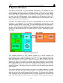
5. System Structure …………………………………………………………………….. 37
5.1. Motor Driver ……………………………………………………………………… 38
5.1.1. Data Transference ………………………………………………………… 39
5.1.2. The Structure BUFFER …………………………………………………… 39
5.1.3. Program Structure ……………………………………………………….… 40
5.1.3.1. The program-module caninit ……………………………………. 40
5.1.3.2. The program-module canio ……………………………………… 40
5.1.3.3. The real-time program-modules ………………………………… 43
5.2. PC Driver …………………………………………………………………………. 44
5.2.1. CAN-Bus Card ……………………………………………………………. 46
5.2.2. User Interface (Communication Module) ………………………………… 47
5.2.3. Driver Program ……………………………………………………………. 48
5.2.3.1. Initialization Phase ………………………………………………. 48
5.2.3.2. Operating Phase …………………………………………………. 50
5.2.3.3. Termination ……………………………………………………… 53
5.3. Matlab User Interface ……………………………………………………………... 53
5.3.1. Initialization Phase ………………………………………………………… 56
5.3.2. Operating Phase …………………………………………………………… 57
5.3.3. Termination ………………………………………………………………... 60
6. Procedures …………………………………………………………………………… 61
6.1. Matlab …………………………………………………………………………….. 61
6.1.1. Change the properties of the Main Window ……………………………… 61
6.1.2. Change the properties of a uicontrol ……………………………………… 63
6.1.3. Change the Cyclic Codes …………………………………………………. 67
6.1.4. Introduce a new Initial Code ……………………………………………… 67
6.1.5. Introduce a new uicontrol …………………………………………………. 67
6.1.5. Introduce a button to a new window ………………………………………. 68
6.2. Visual C++ ………………………………………………………………………… 68
6.2.1. Configure Visual C++ to be able to compile ……………………………… 70
6.2.2. Introduce a new Cyclic Code ……………………………………………… 71
6.2.3. Change the Sampling Time ……………………………………………….. 71
-2-
User Interface for communication through CAN-Bus
6.2.4. Change the Icon …………………………………………………………… 72
6.2.5. Introduce a new element in the Main Window ……………………………. 72
6.2.5.1. Button …………………………………………………………… 73
6.2.5.2. Static Text ………………………………………………………. 73
6.2.5.3. Edit Box …………………………………………………………. 74
6.2.6. Introduce a new variable …………………………………………………... 74
6.3. OS-9000 …………………………………………………………………………... 75
6.3.1. Enable the eighth receive buffer …………………………………………... 75
7. Installation and User Manual ……………………..………………………………… 76
Bibliography……………………………………………….…………………………….. 78
Figure Index ………………………………………………….…………………………. 79
Char of Variables ………………………………………………………………………. 81
Program Code ………………………………………………………………………….. 84
-3-
User Interface for communication through CAN-Bus
1. INTRODUCTION
1.1. Presentation
The present work pretends to resume the effort to design and to implement a
program whose aim is double: to establish the communication between a PC
which performs the role of master, and several motors and, on the other hand,
to be an easy, intuitive user interface, capable to show the evolution of the
motors and to control them as well. If the reader compares theses goals with
the description and objectives in the case of a SCADA system could realise that
they are such the same. In fact, SCADA stands for Supervisory Control And
Data Acquisition. As the name indicates, it is not a full control system, but rather
focuses on the supervisory level. As such, it is a purely software package that is
positioned on top of hardware to which it is interfaced, in general via
Programmable Logic Controllers (PLCs), or other commercial hardware
modules.
Furthermore, the environment where the communication is performed is a field
bus, the CAN Bus. CAN is the acronym for Controller Area Network. It is a open
protocol for industrial use and conceived as a high security protocol, limited to
the levels 1, 2 and 7 of the OSI model.
1.2. Actual Situation
SCADA systems are widely used in industry for Supervisory Control and Data
Acquisition of industrial processes. Companies that are members of
standardisation committees (e.g. OPC, OLE for Process Control) and are thus
setting the trends in matters of IT technologies generally develop these
systems. As a matter of fact, they are now also penetrating the experimental
physics laboratories for the controls of ancillary systems such as cooling,
ventilation, power distribution, etc. More recently they were also applied for the
controls of smaller size particle detectors such as the L3 muon detector and the
NA48 experiment, to name just two examples at CERN. SCADA systems have
made substantial progress over the recent years in terms of functionality,
scalability, performance and openness such that they are an alternative to in
house development even for very demanding and complex control systems as
those of physics experiments. This paper describes SCADA systems in terms of
their architecture, their interface to the process hardware, the functionality and
application development facilities they provide. Some attention is paid to the
industrial standards to which they abide their planned evolution as well as the
potential benefits of their use.
Many vehicles already have a large number of electronic control systems. The
growth of automotive electronics is the result partly of the customer‘s wish for
better safety and greater comfort and partly of the government‘s requirements
for improved emission control and reduced fuel consumption. Control devices
that meet these requirements have been in use for some time in the area of
engine timing, gearbox and carburettor throttle control and in anti-block systems
(ABS) and acceleration skid control (ASC). The complexity of the functions
-4-
User Interface for communication through CAN-Bus
implemented in these systems necessitates an exchange of data between
them. With conventional systems, data is exchanged by means of dedicated
signal lines, but this is becoming increasingly difficult and expensive as control
functions become ever more complex. In the case of complex control systems
(such as Motronic) in particular, the number of connections cannot be increased
much further. Moreover, a number of systems are being developed which
implement functions covering more than one control device.
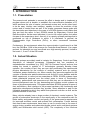
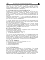
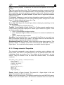
If we also consider future developments aimed at overall vehicle optimization, it
becomes necessary to overcome the limitations of conventional control device
linkage. This can only be done by networking the system components using a
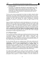
serial data bus system. lt was for this reason that Bosch developed the
”Controller Area Network” (CAN). Using CAN, peer stations (controllers,
sensors and actuators) are connected via a serial bus.
Figure 1. CAN in vehicles
The CAN protocol, which corresponds to the data link layer in the ISO/OSI
reference model, meets the real-time requirements of automotive applications.
Unlike cable trees, the network protocol detects and corrects transmission
errors caused by electromagnetic interference. Additional advantages of such a
network are the easy configurability of the overall system and the possibility of
central diagnosis. The purpose of using CAN in vehicles is to enable any station
to communicate with any other without putting too great a load on the controller
computer.
The use of CAN in most of European passenger cars and the decision by truck
and off-road vehicle manufacturers for CAN led to the availability of CAN chips
for more than 10 years. Other high volume markets, like domestic appliances
and industrial control, also increase the CAN sales figures and guarantee the
availability for the future. Up to spring 1997 there have been more than 50
million CAN nodes installed. One of the outstanding features of the CAN
protocol is its high transmission reliability. The CAN controller registers a
stations error and evaluates it statistically in order to take appropriate
measures. These may extend to disconnecting the CAN node producing the
errors.
-5-
User Interface for communication through CAN-Bus
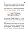
1.3. Objectives
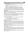
The present work deals with designing a program to be used in the practices in
the university which has taken me in. So, these programs are implemented in
the Laboratory of Mechatronic (LMO) for a subject at the Fachhochschule
München. The goal of the practices is the understanding and study of the
behaviour of the motors, their states and its control. Without a convenient
system the control becomes tedious and complex, where the PC is just a
platform for the Operative System of the motor controller.
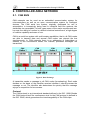
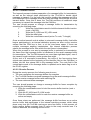
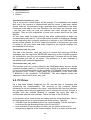
Figure 2. Objective System
As the figure shows, we are handling with a SCADA system, as the PC is
supposed to supervise and control the motors, besides to manage the bus. This
is a distributed system; the motor has its own integrated controller and the task
of the PC is to change the parameters in the controller and take the information
from them to show to the user.
This Final Project of Career explains the adopted solutions to control every
motor independently from the other. The objectives are to get a fast, clear
communication between the PC and the motor through a CAN Bus and to
present, moreover, a user interface where the commands are unnecessary and
the alumni can merely focus on the motor. No knowledge in computing should
be required but the capacity to read and understand.
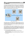
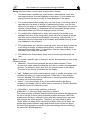
To sum up three programs have been written:
1 The communication program in every motor, which will require an
entrance from the user, a number to identificate everyone. The motors are
slaves for the computer.
2 The communication program for the personal computer (PC), which acts
as the master.
-6-
User Interface for communication through CAN-Bus
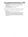
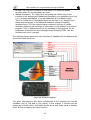
3 The user interface program, which communicates with the communication
program in the PC and it’s implemented in Matlab.
Figure 3. Structure of the Objective System
Due to initial specifications for the programs I had to make them in two different
programming languages: C++ and Matlab. The nature of the CAN bus driver
commands the program Visual C++ or Delphi, so I have chosen the knownest
one for the communication. On the other hand, for the user interface, the
program Matlab combines simplicity to program (and modify, characteristic very
important that lets changes in future extensions) and a very powerful tool to
handle the incoming data.
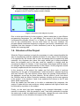
1.4. Structure of the Project
What this Project contains is simply the necessary to make comprehensible the
way of programming and the adopted solutions in every step in the developing.
It is supposed by the reader side to have knowledge about programming and
networks. Any engineer who takes this script should get a deep perception
about the programs and in this way could be capable to change what be
necessary to adapt it to him/her. In fact, the present work began with the idea to
be changed by the responsible teacher of the subject. So the programs should
be clearly explained and the structure firmly ordered.
In the structure of the project the reader can find three sorts of sections
depending on the part of comprehension: initial information, adopted solutions
and user manual. First, the sections inform about the general functionalities of
the hardware, as well as the driver libraries. So the section 2 and 4 are about
the CAN Bus and the Motor Controller hardware, sticking out the main aspects
in the project. In the sections 3 and 4 are explained the drivers in the PC and
Motor sides respectively.
Once the reader has the basis to be able to understand the programs, the
section 5 deals with the main solutions, widely explained with figures which can
be followed by a profane in the subject.
Finally, as the work has been designed to be changed afterwards, a user
manual is imperative. With the sections 6 and 7 has been pretended to explain
the easier way to add any additional functionality, change the sent codes for the
communication or even transform the aspect of the windows.
-7-
User Interface for communication through CAN-Bus
2. CONTROLLER AREA NETWORK
2.1. CAN BUS
CAN networks can be used as an embedded communication system for
microcontrollers as well as an open communication system for intelligent
devices. The CAN serial bus system, originally developed for use in
automobiles, is increasingly being used in industrial field bus systems, the
similarities are remarkable. In both cases some of the major requirements are:
low cost, the ability to function in a difficult electrical environment, a high degree
of realtime capability and ease of use.
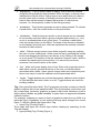
CAN is a serial bus system with multi-master capabilities, that is, all CAN nodes
are able to transmit data and several CAN nodes can request the bus
simultaneously. In CAN networks there is no addressing of subscribers or
stations in the conventional sense, but instead, prioritized messages are
transmitted.
Figure 4. Data Exchange
A transmitter sends a message to all CAN nodes (broadcasting). Each node
decides on the basis of the identifier received whether it should process the
message or not. The identifier also determines the priority that the message
enjoys in competition for bus access.
Protocol
The CAN protocol is an international standard defined in the ISO 11898. Beside
the CAN protocol itself the conformance test for the CAN protocol is defined in
the ISO 16845, which guarantees the interchangeability of the CAN chips.
-8-
User Interface for communication through CAN-Bus
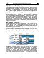
2.1.1. Principles of Data Exchange
CAN is based on the “broadcast communication mechanism”, which is based on
a message-oriented transmission protocol. It defines message contents rather
than stations and station addresses. Every message has a message identifier,
which is unique within the whole network since it defines content and also the
priority of the message. This is important when several stations compete for bus
access (bus arbitration).
As a result of the content-oriented addressing scheme a high degree of system
and configuration flexibility is achieved. It is easy to add stations to an existing
CAN network without making any hardware or software modifications to the
present stations as long as the new stations are purely receivers. This allows for
a modular concept and also permits the reception of multiple data and the
synchronization of distributed processes. Also, data transmission is not based
on the availability of specific types of stations, which allows simple servicing and
upgrading of the network.
Real-Time Data Transmission
In real-time processing the urgency of messages to be exchanged over the
network can differ greatly: a rapidly changing dimension, e.g. engine load, has
to be transmitted more frequently and therefore with less delays than other
dimensions, e.g. engine temperature.
The priority, at which a message is transmitted compared to another less urgent
message, is specified by the identifier of each message. The priorities are laid
down during system design in the form of corresponding binary values and
cannot be changed dynamically. The identifier with the lowest binary number
has the highest priority.
Figure 5. Arbitration in CAN Bus
Bus access conflicts are resolved by bit-wise arbitration of the identifiers
involved by each station observing the bus level bit for bit. This happens in
accordance with the wired-and-mechanism, by which the dominant state
overwrites the recessive state. All those stations (nodes) with recessive
transmission and dominant observation lose the competition for bus access. All
those “losers” automatically become receivers of the message with the highest
-9-
User Interface for communication through CAN-Bus
priority and do not re-attempt transmission until the bus is available again.
Transmission requests are handled in order of their importance for the system
as a whole. This proves especially advantageous in overload situations. Since
bus access is prioritized on the basis of the messages, it is possible to
guarantee low individual latency times in real-time systems.
On the other hand, depending on the size of the propagation delay segment the
maximum possible bus length at a specific data rate (or the maximum possible
data rate at a specific bus length) can be determined. The signal propagation is
determined by the two nodes within the system that are farthest apart from each
other. It is the time that it takes a signal to travel from one node to the one
farthest apart (taking into account the delay caused by the transmitting and
receiving node), synchronization and the signal from the second node to travel
back to the first one. Only then can the first node decide whether its own signal
level (recessive in this case) is the actual level on the bus or whether it has
been replaced by the dominant level by another node. This fact is important for
bus arbitration.
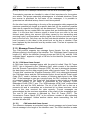
2.1.2. Message Frame Format
The CAN protocol supports two message frame formats, the only essential
difference being in the length of the identifier. The “CAN base frame” supports a
length of 11 bits for the identifier (formerly known as CAN 2.0 A), and the “CAN
extended frame” supports a length of 29 bits for the identifier (formerly known
as CAN 2.0 B).
2.1.2.1. CAN base frame format
A CAN base frame message begins with the start bit called “Start Of Frame
(SOF)”, this is followed by the “Arbitration field” which consist of the identifier
and the “Remote Transmission Request (RTR)” bit used to distinguish between
the data frame and the data request frame called remote frame. The following
“Control field” contains the “IDentifier Extension (IDE)” bit to distinguish between
the CAN base frame and the CAN extended frame, as well as the “Data Length
Code (DLC)” used to indicate the number of following data bytes in the “Data
field”. If the message is used as a remote frame, the DLC contains the number
of requested data bytes. The “Data field” that follows is able to hold up to 8 data
byte. The integrity of the frame is guaranteed by the following “Cyclic
Redundant Check (CRC)” sum. The “ACKnowledge (ACK) field” compromises
the ACK slot and the ACK delimiter. The bit in the ACK slot is sent as a
recessive bit and is overwritten as a dominant bit by those receivers, which
have at this time received the data correctly. Correct messages are
acknowledged by the receivers regardless of the result of the acceptance test.
The end of the message is indicated by “End Of Frame (EOF)”. The
“Intermission Frame Space (IFS)” is the minimum number of bits separating
consecutive messages. Unless another station starts transmitting, the bus
remains idle after this.
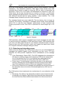
2.1.2.2.
CAN extended frame format
The difference between an extended frame format message and a base frame
format message is the length of the identifier used. The 29-bit identifier is made
-10-
User Interface for communication through CAN-Bus
up of the 11-bit identifier (“base identifier”) and an 18-bit extension (“identifier
extension”). The distinction between CAN base frame format and CAN
extended frame format is made by using the IDE bit, which is transmitted as
dominant in case of an 11-bit frame, and transmitted as recessive in case of a
29-bit frame. As the two formats have to co-exist on one bus, it is laid down
which message has higher priority on the bus in the case of bus access collision
with different formats and the same identifier / base identifier: The 11-bit
message always has priority over the 29-bit message.
The extended format has some trade-offs: The bus latency time is longer (in
minimum 20 bit-times), messages in extended format require more bandwidth
(about 20 %), and the error detection performance is lower (because the
chosen polynomial for the 15-bit CRC is optimized for frame length up to 112
bits).
Figure 6. Telegram
CAN controllers, which support extended frame format messages are also able
to send and receive messages in CAN base frame format. CAN controllers that
just cover the base frame format do not interpret extended frames correctly.
However there are CAN controllers, which only support the base frame format
but recognize extended messages and ignore them.
2.1.3. Detecting and signaling errors
Unlike other bus systems, the CAN protocol does not use acknowledgement
messages but instead signals errors immediately as they occur. For error
detection the CAN protocol implements three mechanisms at the message
level:
• Cyclic Redundancy Check (CRC): The CRC safeguards the information in
the frame by adding a frame check sequence (FCS) at the transmission
end. At the receiver this FCS is re-computed and tested against the
received FCS. If they do not match, there has been a CRC error.
• Frame check: This mechanism verifies the structure of the transmitted
frame by checking the bit fields against the fixed format and the frame
size. Errors detected by frame checks are designated “format errors”.
• ACK errors: Receivers of a message acknowledge the received frames. If
the transmitter does not receive an acknowledgement an ACK error is
indicated.
The CAN protocol also implements two mechanisms for error detection at the
bit level:
• Monitoring: The ability of the transmitter to detect errors is based on the
monitoring of bus signals. Each station that transmits also observes the
bus level and thus detects differences between the bit sent and the bit
-11-
User Interface for communication through CAN-Bus
•
received. This permits reliable detection of global errors and errors local
to the transmitter.
Bit stuffing: The coding of the individual bits is tested at bit level. The bit
representation used by CAN is “Non Return to Zero (NRZ)” coding. The
synchronization edges are generated by means of bit stuffing. That
means after five consecutive equal bits the transmitter inserts a stuff bit
into the bit stream. This stuff bit has a complementary value, which is
removed by the receivers.
If one or more errors are discovered by at least one station using the above
mechanisms, the current transmission is aborted by sending an “error frame”.
This prevents other stations from accepting the message and thus ensures the
consistency of data throughout the network. After transmission of an erroneous
message that has been aborted, the sender automatically re-attempts
transmission (automatic re-transmission). Nodes may again compete for bus
access.
However effective and efficient the method described may be, in the event of a
defective station it might lead to all messages (including correct ones) being
aborted. If no measures for self-monitoring were taken, the bus system would
be blocked by this. The CAN protocol therefore provides a mechanism to
distinguish sporadic errors from permanent errors and local failures at the
station. This is done by statistical assessment of station error situations with the
aim of recognizing a station’s own defects and possibly entering an operation
mode in which the rest of the CAN network is not negatively affected. This may
go as far as the station switching itself off to prevent other nodes’ messages
erroneously from being recognized as incorrect .
2.1.4. Physical Layer
The Controller Area Network (CAN) protocol defines the data link layer and part
of the physical layer in the OSI model, which consists of seven layers. The
International Standards Organization (ISO) defined a standard, which
incorporates the CAN specifications as well as a part of physical layer: the
physical signaling, which comprises bit encoding and decoding (Non-Return-toZero, NRZ) as well as bit timing and synchronization.
On the bit-level (OSI level one, physical layer) CAN uses synchronous bit
transmission. This enhances the transmitting capacity but also means that a
sophisticated method of bit synchronization is required. While bit
synchronization in a character-oriented transmission (asynchronous) is
performed upon the reception of the start bit available with each character, a
synchronous transmission protocol there is just one start bit available at the
beginning of a frame. To enable the receiver to correctly read the messages,
continuous resynchronization is required. Phase buffer segments are therefore
inserted before and after the nominal sample point within a bit interval.
The CAN protocol regulates bus access by bit-wise arbitration. The signal
propagation from sender to receiver and back to the sender must be completed
within one bit-time. For synchronization purposes a further time segment, the
propagation delay segment, is needed in addition to the time reserved for
-12-
User Interface for communication through CAN-Bus
synchronization, the phase buffer segments. The propagation delay segment
takes into account the signal propagation on the bus as well as signal delays
caused by transmitting and receiving nodes.
Figure 7. ISO / OSI Model
Nominal bit-time
Two types of synchronization are distinguished: hard synchronization at the
start of a frame and resynchronization within a frame.
• After a hard synchronization the bit time is restarted at the end of the sync
segment. Therefore the edge, which caused the hard synchronization, lies
within the sync segment of the restarted bit time.
• Resynchronization shortens or lengthens the bit time so that the sample
point is shifted according to the detected edge
Figure 8. Nominal Bit Time
-13-
User Interface for communication through CAN-Bus
2.1.5. Physical media
Electrical signals on the bus are reflected at the ends of the electrical line
unless measures against that have been taken. For the node to read the bus
level correctly it is important that signal reflections are avoided. This is done by
terminating the bus line with a termination resistor at both ends of the bus and
by avoiding unnecessarily long stubs lines of the bus. The highest possible
product of transmission rate and bus length line is achieved by keeping as close
as possible to a single line structure and by terminating both ends of the line.
Specific recommendations for this can be found in the according standards (i.e.
ISO 11898-2 and -3). It is possible to overcome the limitations of the basic line
topology by using repeaters, bridges or gateways.
The connection between a CAN controller chip and a two-wire differential bus a
variety of CAN transceiver chips according to different physical layer standards
are available (see below ISO 11898-2 and –3, etc.).
Figure 9. Generic CAN Montage
This interface basically consists of a transmitting amplifier and a receiving
amplifier transceiver = transmit and receive). Aside from the adaptation of the
signal representation between chip and bus medium the transceiver has to
meet a series of additional requirements. As a transmitter it provides sufficient
driver output capacity and protects the on-controller-chip driver against
overloading. It also reduces electromagnetical radiation. As a receiver the CAN
transceiver provides a defined recessive signal level and protects the oncontroller-chip input comparator against over-voltages on the bus lines. It also
extends the common mode range of the input comparator in the CAN controller
and provides sufficient input sensitivity. Furthermore it detects bus errors such
as line breakage, short circuits, shorts to ground, etc. A further function of the
transceiver can also be the galvanic isolation of a CAN node and the bus line.
-14-
User Interface for communication through CAN-Bus
2.2. CANOpen
CANopen is a CAN-based higher layer protocol. It was developed as a
standardized embedded network with highly flexible configuration capabilities.
CANopen was designed for motion-oriented machine control networks, such as
handling systems. By now it is used in many various fields, such as medical
equipment, off-road vehicles, maritime electronics, public transportation,
building automation, etc.
CANopen was pre-developed in an Esprit project under the chairmanship of
Bosch. In 1995, the CANopen specification was handed over to the CAN in
Automation (CiA) international users’ and manufacturers’ group. Originally, the
CANopen communication profile was based on the CAN Application Layer
(CAL) protocol.
The CANopen application layer and communication profile supports direct
access to device parameters and transmission of time-critical process data. The
CANopen network management services simplify project design, system
integration, and diagnostics. In each decentralized control application, different
communication services and protocols are required. CANopen defines all these
services and protocols as well as the necessary communication objects.
CANopen unburdens the developer from dealing with CAN-specific details such
as bit-timing and implementation-specific functions. It provides standardized
communication objects for real-time data (Process Data Objects, PDO),
configuration data (Service Data Objects, SDO), and special functions (Time
Stamp, Sync message, and Emergency message) as well as network
management data (Boot-up message, NMT message, and Error Control).
2.2.1. Process Data Objects
Process Data Objects (PDOs) are mapped to a single CAN frame using up to 8
bytes of the data field to transmit application objects. Each PDO has a unique
identifier and is transmitted by only one node, but it can be received by more
than one (producer/consumer communication).
PDO Transmissions
PDO transmissions may be driven by an internal event, by an internal timer, by
remote requests and by the Sync message received:
- Event- or timer-driven: An event (specified in the device profile) triggers
message transmission. An elapsed timer additionally triggers the
periodically transmitting nodes.
- Remotely requested: Another device may initiate the transmission of an
asynchronous PDO by sending a remote transmission request (remote
frame).
- Synchronous transmission: In order to initiate simultaneous sampling of
input values of all nodes, a periodically transmitted Sync message is
required. Synchronous transmission of PDOs takes place in cyclic and
acyclic transmission mode. Cyclic transmission means that the node
waits for the Sync message, after which it sends its measured values. Its
PDO transmission type number (1 to 240) indicates the Sync rate it
-15-
User Interface for communication through CAN-Bus
listens to (how many Sync messages the node waits before the next
transmission of its values). Acyclically transmitted synchronous PDOs
are triggered by a defined application-specific event. The node transmits
its values with the next Sync message but will not transmit again until
another application-specific event has occurred.
Figure 10. PDO Transmission
PDO Mapping
The default mapping of application objects as well as the supported
transmission mode is described in the Object Dictionary for each PDO. PDO
identifiers should have high priority to guarantee a short response time. PDO
transmission is not confirmed. The PDO mapping defines which application
objects are transmitted within a PDO. It describes the sequence and length of
the mapped application objects. A device that supports variable mapping of
PDOs must support this during the pre-operational state. If dynamic mapping
during operational state is supported, the SDO Client is responsible for data
consistency.
Figure 11. PDO Mapping
2.2.2. Service Data Object
A Service Data Object (SDO) reads from entries or writes to entries of the
Object Dictionary. The SDO transport protocol allows transmitting objects of any
size. The first byte of the first segment contains the necessary flow control
information including a toggle bit to overcome the well-known problem of doubly
received CAN frames. The next three byte of the first segment contain index
and sub-index of the Object Dictionary entry to be read or written. The last four
-16-
User Interface for communication through CAN-Bus
byte of the first segment are available for user data. The second and the
following segments (using the very same CAN identifier) contain the control
byte and up to seven byte of user data. The receiver confirms each segment or
a block of segments, so that a peer-to-peer communication (client/server) takes
place.
2.2.3. Network Management
The Network Management objects include Boot-up message, Heartbeat
protocol, and NMT message.
Boot-up message, and Heartbeat protocol are implemented as single CAN
frames with 1-byte data field.
Figure 12. Network Management
2.2.3.1. NMT Message
The NMT message is mapped to a single CAN frame with a data length of 2
byte. Its identifier is 0. The first byte contains the command specifier and the
second contains the Node-ID of the device that must perform the command (in
the case of Node-ID 0 all nodes have to perform the command). The NMT
message transmitted by the NMT master forces the nodes to transit to another
NMT state. The CANopen state machine specifies the states Initialisation, PreOperational, Operational and Stopped. After power-on, each CANopen device
is in the state Initialization and automatically transits to the state Preoperational. In this state, transmission of SDOs is allowed. If the NMT master
has set one or more nodes into the state Operational, they are allowed to
transmit and to receive PDOs. In the state Stopped no communication is
allowed except that of NMT objects.
Figure 13. NMT Message
The state Initialization is divided into three sub-states in order to enable a
complete or partial reset of a node. In the sub-state Reset Application the
parameters of the manufacturer-specific profile area and the standardized
-17-
User Interface for communication through CAN-Bus
device profile area are set to their power-on values. In the sub-state Reset
Communication the parameters of the communication profile area are set to
their power-on values. The third sub-state is initialising, which a node enters
automatically after power-on. Power-on values are the last stored parameters.
2.2.3.2. Boot-up Message
A device sends the Boot-up message to indicate to the NMT master that it has
reached the state Pre-operational. This occurs whenever the device initially
boots-up but also after a power-out during operation. The Boot-up message has
the same identifier as the Heartbeat object, however, its data content is zero.
2.2.3.3. Emergency Message
The Emergency message is triggered by the occurrence of a device internal
error situation and is transmitted from an Emergency producer on the
concerned application device. This makes them suitable for interrupt type error
alerts.
Figure 14. Emergency Message
An Emergency message is transmitted only once per ‘error event’. As long as
no new errors occurs on a device, no further Emergency message can be
transmitted. Zero or more Emergency consumers may receive these. The
reaction of the Emergency consumer is application-specific. CANopen defines
several Emergency Error Codes to be transmitted in the Emergency message,
which is a single CAN frame with 8 data byte.
2.2.3.4. Time-Stamp Object (Time)
By means of Time-Stamp, a common time frame reference is provided to
application devices. It contains a value of the type Time-of-Day. This object
transmission follows the producer/consumer push model. The associated CAN
frame has the pre-defined identifier 256 and a data field of 6-byte length.
Figure 15. Time-Stamp Object
-18-
User Interface for communication through CAN-Bus
2.2.4. Error Control
The Heartbeat protocol is for error control purposes and signals the presence of
a node and its state. The Heartbeat message is a periodic message of the node
to one or several other nodes. It indicates that the sending node is still working
properly.
Besides Heartbeat protocol there exists an old and out-dated error control
services, which is called Node and Life Guarding protocol. It is not recommend
for implementation.
Figure 16. Error Control
-19-
User Interface for communication through CAN-Bus
3. VIRTUAL CAN INTERFACE (VCI)
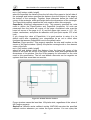
3.1. INTRODUCTION
The choice of the software to implement the driver who controls the
communication is as important as the whole program. Also it must be chosen
with attention. In the present case the best platform to work is the Virtual CAN
Interfaces (VCI). It is a software package for the IXXAT-PC/CAN-Interfaces.
Some general characteristics are:
• Hardware-independent CAN-Applications for PCs.
• Easy application.
• Good real-time behaviour of the VCI.
The aim of the VCI is to provide the user with a unified programming interface
for the various PC/CAN-interface versions of the IXXAT company. For this,
neither the design of the PC-connection (DPRAM, LPT, USB,...) nor the CAN
Controller of the interface used is important. In addition, the VCI makes it
possible to operate several (even different ) cards at the same time.
This concept enables realisation of application programs independent of the
PC/CAN-interface type used. For this, a virtual CAN Controller was defined in
the VCI, the structure of which corresponds to a Basic-CAN-Controller and
which supports operation with 11-bit and 29-bit identifiers. Downstream from
this virtual CAN-Controller a Firmware is installed which organises the message
administration. The virtual CAN-Controller can be present on a PC/CANInterface up to 4 times, whereby simultaneous operation of up to 4 cards is
possible.
The VCI supports:
• Standard and Extended Protocol (11 and 29-bit-Identifier)
• Several CAN-Controllers per interface (if supported by the hardware)
• Simultaneous operation of up to four interfaces by one or more applications
• Baud rates of up to 1000 Kbaud
• Reception of messages via configurable receive queues (FIFO) with time
marker
• Reception of messages via configurable receive buffers with receive
counter.
• Several queues and buffers can be assigned to each CAN-Controller.
• Sending of messages (via configurable send queues)
• Queues can be polled or read per interrupt (Timeout or ´High water mark´)
• Automatic, configurable response to request messages (Remote frames)
(only in 11 Bit Standard protocol) In addition, the VCI supplies statistic data
to the CAN-Bus, to the CAN-Controller, via the data structures and the
PC/CAN-interfaces.
-20-
User Interface for communication through CAN-Bus
3.2. LIMITATIONS
•
•
•
Access to a PC/CAN-interface is only possible for one application. Therefore
several applications cannot share one PC/CAN-interface.
Remote Buffers only possible in 11Bit Standard Mode created, so that presorting can already be carried out by the VCI. All messages recorded in a
Receive queue are provided with a time stamp.
The maximum number of Receive queues which can be configured is 16 per
CAN-Controller.
The Call-back-function is called up from the Interrupt-thread of the VCI. This
gives rise to several limitations:
•
•
In the Call-back-function no time-critical calculations should be carried out,
as otherwise CAN-messages may be lost.
They are located in the Call-back-function in the context of the Interruptthreads. An attempt to access data from its application may fail for this
reason. One way to uncouple Call-back from its application is to start an
application-thread for processing a queue. Incoming CAN-messages are
signalised in their Call-back-function by the setting of an event. The
application-thread waits for this event and carries out processing after the
Event has been set. After the processing step it returns to wait mode.
3.3. TRANSMIT QUEUES
Messages (data and data requests) from the application are sent via Transmit
queues. In this way, when making a request to send, the application does not
need to wait until the CAN-Controller is ready to transmit. Servicing of the
Transmit queue(s) is carried out by the microcontroller of the active PC/CANinterfaces or with passive PC/CAN-interfaces by the Interrupt routine of the PC.
Several queues of different sizes (number of messages) and different priority
can be created. The different priorities of the queues determine the order in
which they are processed by the microcontroller.
The maximum number of Transmit queues per CAN-Controller which can be
configured is 8.
3.4. INTERFACE FUNCTIONS
The VCI-user interface provides the user with a collection of functions for the
PC which access PC/CAN-Interface and handle communication via CAN. The
interface distinguishes four different classes of functions:
• functions for the control and configuration of the PC/CAN interface
• functions for checking and configuration of the CAN-Controller
• functions to receive messages
• functions to send messages
-21-
User Interface for communication through CAN-Bus
3.4.1. Pre-defined Return Codes of the VCI
In order to be able to support other PC/CAN-interface types in future, and as it
is not possible to specify all errors and Return codes today which may occur in
future implementations, all possible Return codes are described via the
following Defines. Additional information (error string and further parameters) is
provided by the Exception handler of the VCI (Call-back-function).
3.4.2. Type Definitions of the Call-back Handler
Call-back handlers are functions coded by the user and called up (in this case
by the VCI) when certain events occur. In this case they are used for error
display and error handling, processing of interrupt messages or for issuing test
or initialisation protocols. In order that the VCI can recognise and carry out
these Call-back handlers, these functions must correspond to the set type
definitions and introduce them to the VCI via ‘VCI_PrepareBoard’.
If, for example, an interrupt is triggered by a Receive queue, a corresponding
function (Call-back handler) must be coded by the user. This function must be
coded for each installed PC/CAN-interface which should trigger interrupts. The
user decides whether to use the possibilities of Call-back-handling or to do
without and just transfer ‘VCI_PrepareBoard’ to a NULL-Pointer instead of to a
function pointer.
3.4.2.1. Receive-Interrupt-Handler
The queue messages (Timeout or “High water mark”) received via the interrupt
are transferred to this function, provided this was specified via the
VCI_ConfigQueue.
This Call-back handler is used for 2 different interrupt mechanisms:
• Transmission of messages (max. 13 messages simultaneously)
• Signal of a Receive queue for the application
In the first case the messages are given to the Interrupt-Callbackfunction by
parameter. This mode should be used only at low message rates.
Within the Receive-Interrupt-Callbackfunction you should pay attention to the
following points:
• Avoid time consuming calculations because the Interrupt-Thread is blocked
while you are in the Callbackfunction and no more messages could be
handled during this time.
• Sometimes it could be difficult to access application data within the ReceiveInterrupt-Callbackfunction because you are in the context of the InterruptThread.
In the second mechanism the call to the Callbackfunction is only a signal to the
application (count = 0) and means that messages are in the receive queue that
should be read using the VCI_ReadQueObj function. This could be used for
example to set a worker thread in the running state (by setting an event) which
could process the messages.
3.4.2.2. Exception-Handlers
This function is always called up when an error has occurred in a system
-22-
User Interface for communication through CAN-Bus
function. In this case this error is not only displayed via the Return value, but is
also handed on to the Exception handler. Thus the user has two ways to handle
errors, whereby the one via the Exception handler provides a clearer program
code.
Strings with a more exact error specification are transferred to the Exception
handler which can be output in an error window or written in a file.
These Null-terminated strings (without control character) with a max. length of
60 characters state the function name of the function in which the error has
occurred and also the error is specified more precisely.
For each PC/CAN-interface a separate Exception handler must be coded.
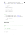
3.5. PROGRAMMING WITH VCI
VCI provides a complete set of functions for programming the CAN controllers
and for carrying out CAN communication with other bus subscribers. The broad
ability to parameterise VCI functions allows the highly flexible use of the
programming library in all CAN application fields.
All functions are implemented according to the C stdcall call convention. For
feedback messages of the API to the application, either call-backs or Windows
messages can be selected by the programmer. Alternatively the receive queue
can be polled.
3.5.1.Callbacks vs. WM Handler
In a typical application case, VCI is operated with one receive and one transmit
queue. For VCI receive queue handling in Visual C++ there are 3 alternatives:
Polling, interrupt processing and event operation as described in the VCI V2
Programming Manual. For interrupt processing and event operation the
notifications can be done via a callback function or a windows message.
The initial specifications for the program (the use of Matlab) imposes conditions
whom in the beginning could be free to election. That is, in a normal situation
we could select the best way to handle the interruptions (either Callbacks or
Windows Handler) and it be necessary a discussion about it. However in this
case there’s no place to these thoughts. A Windows Handler gives no possibility
for the communication with Matlab, so the callbacks appear as the only way for
us.
-23-
User Interface for communication through CAN-Bus
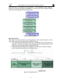
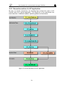
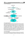
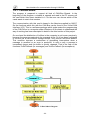
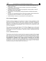
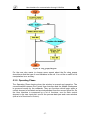
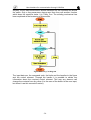
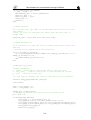
3.5.2. General execution of a VCI application
By way of a simple introduction, the following figure shows the order of VCI
function calls for a typical application. This sequence is first sub-divided into
board selection, initialisation phase, operating phase and termination.
Figure 17. General Execution of a VCI Application
-24-
User Interface for communication through CAN-Bus
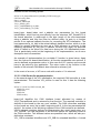
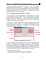
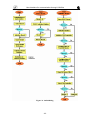
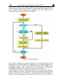
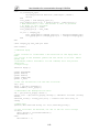
3.5.3.VCI Initialization
Figure 18. VCI Initialization Process
3.5.3.1. Board selection
For initialisation of the CAN interface board, the board type and the computerspecific board identification are required. Both pieces of information can be
defined using the so-called IXXAT registry functions. For this, the XatxxReg.h
header and the associated Xat11Reg.lib library must be integrated. After that
the standard IXXAT hardware selection dialog can be opened with the
command XAT_SelectHardware( ). In the hardware selection dialog the user
can select the board to be used. Its main features are given in the structure
XAT_BoardCFG. The elements of this structure, in particular board_no and
board_type, are required for the initialization of the CAN interface board. If an
application always uses the same CAN board, it is recommended to store the
contents of the XAT_BoardCFG structure in the persistent application data, and
not to use the board selection for the subsequent program runs.
3.5.3.2. Board Prepare
As soon as the board is clearly identified, the initialisation part can processed.
First the relevant CAN board for the application is opened and allocated. For
this the function VCI2_PrepareBoard, which works with callbacks, is used.The
-25-
User Interface for communication through CAN-Bus
function has the following syntax:
INT32 VCI2_PrepareBoard(VCI_BOARD_TYPE board_type,
UINT16 board_index,
char* s_addinfo,
UINT8 b_addLength,
VCI_t_PutS fp_puts,
VCI_t_UsrRxIntHdlr fp_int_hdlr,
VCI_t_UsrExcHdlr fp_exc_hdlr);
board_type, board_index and s_addinfo are parameters for the board
identification, which can be used directly from the structure XAT_BoardCFG of
the board selection. b_addLength is the byte length of the zero-terminated
string s_addinfo and can thus also be defined easily. fp_puts is a function
pointer to an optional callback function for recording the VCI initialisation. The
next parameter fp_int_hdlr is the actual callback handler function, which is to be
called for receive signalling as soon as a CAN telegram is received. In the
following parameter fp_exc_hdlr a callback function can again be specified
which is called in the event of a fatal error during the VCI initialisation phase.
This is particularly useful at the beginning of the implementation, as an error
description text is transmitted.
An example of implementation for a suitable C function is given below. Apart
from the values for board identification, all function parameters are optional. 0
can be defined as parameter value. In this case the VCI receive queue would
have to be polled by the application. The return value of the function is the
handle of the relevant CAN board, also referred to as board_hdl.
In the event of an error, a VCI error code with a value < 0 is returned.
3.5.3.3. CAN Controller parameterisation
In the second step of the VCI initialisation, the required CAN controller is to be
parameterised. The function VCI_InitCan is used for this. It has the following
syntax:
INT32 VCI_InitCan( UINT16 board_hdl,
UINT8 can_num,
UINT8 bt0,
UINT8 bt1,
UINT8 mode);
board_hdl identifies the CAN interface board allocated by means of
VCI2_PrepareBoard and is returned by that function. The required controller is
defined on the board by the can_num variable. The CAN controllers available
on the board are count up in order, beginning with 0. In the two parameters bt0
and bt1, the values of the bit-timing registers of the CAN controller are defined VCI2.h already contains defines for programming the usual baud rates, e.g.
VCI_1000KB. The last parameter of the function defies the operating mode of
the CAN controller. Two different values are possible here, which are also predefined as constants:
VCI_11B for standard identifiers and VCI_29B for extended identifiers. A mixed
-26-
User Interface for communication through CAN-Bus
mode is not supported by VCI2!
The return value of the function is a VCI error code. If successful, VCI_OK is
returned, in the event of an error a value of < 0.
3.5.3.5. Queues Configuration
In the next step the VCI receive queue and where applicable the VCI transmit
queue is to be created. This is done with the function VCI_ConfigQueue. It has
the following syntax:
INT32 VCI_ConfigQueue( UINT16 board_hdl,
UINT8 can_num,
UINT8 que_type,
UINT16 que_size,
UINT16 int_limit,
UINT16 int_time,
UINT16 ts_res,
UINT16* p_que_hdl);
The last parameter p_que_hdl is important, as here VCI enters the queue
handle which clearly identifies the relevant queue.
The return value of the function is a VCI error code. If successful, VCI_OK is
returned, in the event of an error a value of < 0.
3.5.3.6. Starting CAN
Initialisation of the VCI is now complete. However, you will not yet receive
anything, as filtering of the receive queue is set as standard so that all
identifiers are blocked. Therefore, in a further step, the filter has to be set that
all or defined messages will be received. This is done with the function
VCI_AssignRxQueObj. To receive all CAN telegrams, use the following
instruction:
VCI_AssignRxQueObj (hBoard, hRxQue, VCI_ACCEPT, 0, 0);
In the last step, which already marks the transition to the operating phase, start
the CAN controller that has just been parameterised. This is done with the
function VCI_StartCan:
INT32 VCI_StartCan( UINT16 board_hdl,
UINT8 can_num );
3.5.4. Operating phase of the application
3.5.4.1. Receive Process
In a VCI application that does not use callbacks and Windows messages, the
receive queue must be polled. For this, VCI provides the function
VCI_ReadQueObj. It is not our case, so we can just not explain this function
deeply.
If a Window message handler is defined, or if working with a VCI Rx callback
function, the allocation of a local VCI receive buffer as with VCI_ReadQueObj is
not necessary, as both the commencement location address of the VCI receive
buffer and the number of the receive objects are supplied directly. In the receive
-27-
User Interface for communication through CAN-Bus
callback handler, the received CAN objects can therefore be accessed
immediately.
In conclusion, a few words on the format of the VCI CAN data themselves:
every CAN message received by VCI is provided in a structure named
VCI_CAN_OBJ. In addition to the CAN telegram (ID + 8 data bytes), this also
includes the timestamp, RTR bit and diverse status information: time_stamp is
the absolute value of the time of reception of the CAN frame, standardized to
the time interval ts_res defined in the function VCI_ConfigQueue. In id, the
identifier of the CAN telegram, both for 11-bit and for 29-bit frames, is right
adjusted. len, rtr and res define a bit field. It is made up of the DLC of the CAN
frame and the RTR bit. The upper three bits of the structure element are
reserved, but not set to 0: a_data contains the data field of the CAN frame. The
number of valid bytes, i.e. the length of the data field, is obtained by len. The
last element VCI_CAN_OBJ.sts contains VCI-internal status information.
3.5.4.2. Transmit Process
Compared with the acceptance of received CAN data, transmission of a CAN
message is fairly simple. The function VCI_TransmitObj available for this has
the following parameters: board_hdl and que_hdl identify the CAN interface
board and the VCI transmit queue. The CAN identifier id, the CAN data field
pData and the length of the data field used len, are transmitted as individual
parameters.
The return value of the function is a VCI error code. If successful, VCI_OK is
returned, in the event of an error a value of < 0.
3.5.4.3. Termination of the application
When terminating the application, it is necessary to call VCI_CancelBoard. This
call must not be made only when unloading the application (or DLL), but must
be made already during the regular run time of the program, for example in the
WM_DESTROY handler function of you dialog class.
It is recommended to deactivate the CAN controller used already at the start of
program deinitialization with VCI_ResetCan, so that no CAN receive telegrams
interfere with program deinitialization.
3.6. NOTES ON PROGRAMMING
The Virtual CAN Interface for Windows is implemented as a Dynamic Link
Library (DLL).
• the DLL is not integrated like a normal C-library but loaded at the run-time of
the application and connected with it dynamically; the functions of the DLL
are therefore located in their own compiled module and must be integrated
in a certain way; integration is explained in Section 3.1.
• the function VCI_Init() should not be used under Windows in normal
operation; however, for the development in an Interpreter environment, it
can be helpful to reset the VCI explicitly with VCI_Init(); however, this should
not apply to the release version of the application; there the
‘VCI_CancelBoard’ must be used. See also the description of VCI_Init().
-28-
User Interface for communication through CAN-Bus
•
for statically linking you need a import library suitable for your system. Most
systems ship with little command-line tools to generate a import library from
the function signatures of a DLL. Is it not possible to generate the import
library you could in all cases load the VCI-DLL dynamically.
3.6.1. Integration of the DLL in an Application
Integration of the DLL can occur in different ways.
• Implizit Import via import library
• Dynamic Import
I will use the implicit import during linking. In this way the generated code is
clearer and easy to understand and the occupied memory is not so large.
Furthermore we need some functions through the whole program. We cannot
load and clear the dynamic libraries every period.
The Header ‘VCI2.H’ contains the prototypes for the exportable functions.
3.6.2. Implicit Import During Linking
The DLL can be integrated in a project file of the application by inserting the
Import-Library. The Import-Library has the same name as the DLL with the file
extension “.LIB”. This contains the entries which the Linker uses to create a
“Relocation Table”. During the run-time, the addresses of the functions of the
DLL are entered here. With this procedure, the library is loaded during the start
of the application. The installation contains libraries for Microsoft Visual C++
5.0, Microsoft Visual C++ 6.0 and Borland C++ Builder. Import-libraries can also
be created for other compilers by means of the Module-Definition-File (ending
“.DEF”) also contained in the installation.
-29-
User Interface for communication through CAN-Bus
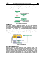
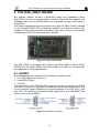
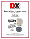
4. THE OAK_EMUF BOARD
The present chapter contains a description about the embedded system
OAK_EMUF used as a programmable controller. Especially the registers and
message-buffers of the CAN-Controller are descripted, as well as the types of
functioning.
This board, manufactured by the enterprise Ing. Büro W. Kanis GmbH, is based
on the PowerPC-RISC-CPU of Motorola. Installed is a special version, with
integrated Flash which includes chip select logic, timer, counter and interrupt
management, CAN, TUP and many other features.
Figure 19. OAK_EMUF Board
The OAK_EMUF is equipped with 4 Mbyte Fast Burst RAM, 2 Mbyte FlashEPROM and 32 kByte SRAM Fast Burst RAMs are used for constant high
throughput also in large applications.
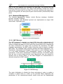
4.1. NODES
The embedded system disposes of the following relevant nodes:
• A 10 Mbit/s Ethernet connection,
• A serial RS-232port
• 2 x CAN
The connection to the CAN-Bus takes place by means of a 9-polygon D-Sub
connector. However it’s important to emphasize that the distribution of the pins
in our connector doesn’t abide by the recommendation of the DS 102-1 norm
from CiA. The following figures show both distributions: the OAK_EMUF one
and the CiA recommendation.
Figure 20. CAN Bus Connection
-30-
User Interface for communication through CAN-Bus
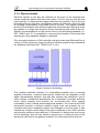
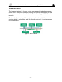
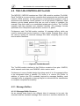
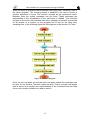
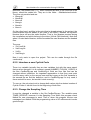
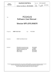
4.2. THE CAN-CONTROLLER TouCAN
The MPC555 / MPC556 contains two CAN 2.0B controller modules (TouCAN).
Each TouCAN is a communication controller that implements the controller area
network (CAN) protocol, an asynchronous communications protocol used in
automotive and industrial control systems. It is a high speed (1 Mbit/sec), short
distance, priority based protocol that can run over a variety of mediums (for
example, fiber optic cable or an unshielded twisted pair of wires). The TouCAN
supports both the standard and extended identifier (ID) message formats
specified in the CAN protocol specification, revision 2.0, part B.
Furthermore each TouCAN module contains 16 message buffers, which are
used for transmit and receive functions. It also contains message filters, which
are used to qualify the received message IDs when comparing them to the
receive buffer identifiers.
Figure 21. TouCAN Structure
The TouCAN module interface to the CAN bus consists of two pins: CANTX0,
which transmit serial data, and CANRX0, which receive serial.
Furthermore it uses a flexible design that allows each of its 16 message buffers
to be designated either a transmit (Tx) buffer or a receive (Rx) buffer. In
addition, to reduce the CPU overhead required for message handling, each
message buffer is assigned an interrupt flag bit to indicate that the transmission
or reception completed successfully.
4.2.1. Message Buffers
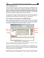
4.2.1.2. Message Buffer Structure
As we already know there’s two different kind of message to be sent: the
extended and the standard message. Each one has a concrete distribution for
-31-
User Interface for communication through CAN-Bus
the buffer for the TouCAN. The following figure display the extended (29-bit) ID
message buffer structure first and nearby the standard (11-bit) ID message
buffer structure.
Figure 22. Message Buffer Structures
In first place I will comment what the common fields means:
- TIME STAMP: Contains a copy of the high byte of the free running timer,
which is captured at the beginning of the identifier field of the frame on
the CAN bus.
- CODE: It is different for Transmit and Receive Buffers. In the Receive
Buffers contains one code of the following:
o NON ACTIVE
o EMPTY
o FULL
o OVERRUN
• BUSY On the other hand the Transmit Buffers have information about
the status:
o Not Ready for Transmit
o Data Frame to be transmitted once, unconditionally
o Remote frame to be transmitted once, and message buffer
becomes an RX message buffer for data frames
o Data frame to be transmitted only as a response to a remote
frame, always
o Data frame to be transmitted only once, unconditionally, and then
only as a response to remote frame, always
- Rx LENGTH: Length (in bytes) of the Rx data stored in offset 0x6
through 0xD of the buffer.This field is written by the TouCAN module,
copied from the DLC (data length code) field of the received frame.
- Tx LENGTH: Length (in bytes) of the data to be transmitted, located in
offset 0x6 through 0xD of the buffer. This field is written by the CPU and
is used as the DLC field value. If RTR (remote transmission request) = 1,
, the frame is a remote frame and will be transmitted without data field,
regardless of the value in Tx length.
- DATA: This field can store up to eight data bytes for a frame. For Rx
frames, the data is stored as it is received from the bus. For Tx frames,
the CPU provides the data to be transmitted within the frame.
- RESERVED: The CPU controls access to this word entry field (16 bits).
-32-
User Interface for communication through CAN-Bus
Now it is the moment to explain the particular fields in both format frames. In the
extended one we find:
- ID[28:18]/[17:15]: Contains the 14 most significant bits of the extended
identifier, located in the ID HIGH word of the message buffer.
- Substitute Remote Request (SRR): Contains a fixed recessive bit,
used only in extended format. Should be set to one by the user for Tx
buffers. It will be stored as received on the CAN bus for Rx buffers.
- ID Extended (IDE): If extended format frame is used, this field should be
set to one. If zero, standard format frame should be used.
- ID[14:0]: Bits [14:0] of the extended identifier, located in the ID LOW
word of the message buffer.
- Remote Transmission Request (RTR): This bit is located in the least
significant bit of the ID LOW word of the message buffer; 0 = Data
Frame, 1 = Remote Frame.
Finally the particular fields for the standard buffers are:
- 16 Bit Time-Stamp: The ID LOW word, which is not needed for standard
format, is used in a standard format buffer to store the 16-bit value of the
free-running timer which is captured at the beginning of the identifier field
of the frame on the CAN bus.
- ID[28:18]: Contains bits [28:18] of the identifier, located in the ID HIGH
word of the message buffer. The four least significant bits in this register
(corresponding to the IDE bit and ID[17:15] for an extended identifier
message) must all be written as logic zeros to ensure proper operation of
the TouCAN.
- RTR: This bit is located in the ID HIGH word of the message buffer; 0 =
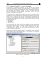
data frame, 1 = remote frame.
- RTR/SRR Bit Treatment: If the TouCAN transmits this bit as a one and
receives it as a zero, an “arbitration loss” is indicated. If the TouCAN
transmits this bit as a zero and is receives it as a one, a bit error is
indicated. If the TouCAN transmits a value and receives a matching
response, a successful bit transmission is indicated.
4.2.1.2. Serial Message Buffers
To allow double buffering of messages, the TouCAN has two shadow buffers
called serial message buffers. The TouCAN uses these two buffers for buffering
both received messages and messages to be transmitted. Only one serial
message buffer is active at a time, and its function depends upon the operation
of the TouCAN at that time. At no time does the user have access to or visibility
of these two buffers.
4.2.1.3. Message Buffer Activation/Deactivation Mechanism
Each message buffer must be activated once the user configures it for the
desired operation. A buffer is activated by writing the appropriate code to the
control/status word for that buffer. Once the buffer is activated, it will begin
participating in the normal transmit and receive processes.
A buffer is deactivated by writing the appropriate deactivation code to the
control/status word for that buffer. A buffer is typically deactivated when the
-33-
User Interface for communication through CAN-Bus
user desires to reconfigure the buffer (for example to change the buffer’s
function from Rx to Tx or Tx to Rx). The buffer should also be deactivated
before changing a receive buffer’s message identifier or before loading a new
message to be transmitted into a transmit buffer.
4.2.1.4. Message Buffer Lock/Release/Busy Mechanism
In addition to the activation/deactivation mechanism, the TouCAN also uses a
lock/release/busy mechanism to ensure data coherency during the receive
process. The mechanism includes a lock status for each message buffer and
uses the two serial message buffers to facilitate frame transfers within the
TouCAN.
Reading the control/status word of a receive message buffer triggers the lock
for that buffer. While locked, a received message cannot be transferred into that
buffer from one of the serial message buffers.
If a message transfer between the message buffer and a serial message buffer
is in progress when the control/status word is read, the BUSY status is indicated
in the code field, and the lock is not activated.
The user can release the lock on a message buffer in one of two ways. Reading
the control/status word of another message buffer locks that buffer, releasing
the previously locked buffer. A global release can also be performed on any
locked message buffer by reading the free-running timer.
4.2.2. Receive Mask Registers
The receive mask registers are used as acceptance masks for received frame
IDs. The following masks are defined:
• A global mask, used for receive buffers 0-13
• Two separate masks for buffers 14 and 15
The value of the mask registers should not be changed during normal
operation. If the mask register data is changed after the masked identifier of a
received message is matched to a locked message buffer, that message will be
transferred into that message buffer once it is unlocked, regardless of whether
that message’s masked identifier still matches the receive buffer identifier.
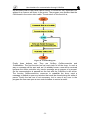
4.2.3. TouCAN Operations
The basic operation of the TouCAN can be divided into three areas:
• Reset and initialization of the module
• Transmit message handling
• Receive message handling
4.2.3.1. TouCAN Initialization
Initialization of the TouCAN includes the initial configuration of the message
buffers and configuration of the CAN communication parameters following a
reset, as well as any reconfiguration which may be required during operation.
On the other hand, in both the transmit and receive processes, the first action in
preparing a message buffer must be to deactivate the buffer by setting its code
field to the proper value. This step is mandatory to ensure data coherency.
-34-
User Interface for communication through CAN-Bus
4.2.3.2. Transmit Process
The transmit process includes preparation of a message buffer for transmission,
as well as the internal steps performed by the TouCAN to decide which
message to transmit. For the user, this involves loading the message and ID to
be transmitted into a message buffer and then activating that buffer as an active
transmit buffer. Once this is done, the TouCAN performs all additional steps
necessary to transmit the message onto the CAN bus.
The user should prepare or change a message buffer for transmission by
executing the following steps.
1.
Write the control/status word to hold the transmit buffer inactive
(code = 0b1000)
2.
Write the ID_HIGH and ID_LOW words
3.
Write the data bytes
4.
Write the control/status word (active Tx code, Tx length)
Once an active transmit code is written to a transmit message buffer, that buffer
begins participating in an internal arbitration process as soon as the receiver
senses that the CAN bus is free, or at the inter-frame space. If there are
multiple messages awaiting transmission, this internal arbitration process
selects the message buffer from which the next frame is transmitted.
When this process is over and a message buffer is selected for transmission,
the frame from that message buffer is transferred to the serial message buffer
for transmission. The TouCAN transmits no more than eight data bytes, even if
the transmit length contains a value greater than eight.
At the end of a successful transmission, the value of the free-running timer
(which was captured at the beginning of the identifier field on the CAN bus), is
written into the time stamp field in the message buffer. The code field in the
control/status word of the message buffer is updated and a status flag is set in
the IFLAG register.
4.2.3.3. Receive Process
During the receive process, the following events occur:
• The user configures the message buffers for reception
• The TouCAN transfers received messages from the serial message buffers
to the receive message buffers with matching IDs
• The user retrieves these messages
The user should prepare or change a message buffer for frame reception by
executing the following steps.
1. Write the control/status word to hold the receive buffer inactive (code =
0b0000)
2. Write the ID_HIGH and ID_LOW words
3. Write the control/status word to mark the receive message buffer as
active and empty
Once these steps are performed, the message buffer functions as an active
receive buffer and participates in the internal matching process, which takes
place every time the TouCAN receives an error-free frame. In this process, all
active receive buffers compare their ID value to the newly received one. If a
match is detected, the following actions occur:
-35-
User Interface for communication through CAN-Bus
1. The frame is transferred to the first (lowest entry) matching receive
message buffer
2. The value of the free-running timer (captured at the beginning of the
identifier field on the CAN bus) is written into the time stamp field in the
message buffer
3. The ID field, data field, and RX length field are stored
4. The code field is updated
5. The status flag is set in the IFLAG register
The user should read a received frame from its message buffer in the following
order:
1. Control/status word (mandatory, as it activates the internal lock for this
buffer)
2. ID (optional, since it is needed only if a mask was used)
3. Data field word(s)
4. Free-running timer (optional, as it releases the internal lock). If the free
running timer is not read, that message buffer remains locked until the
read process starts for another message buffer. Only a single message
buffer is locked at a time. When a received message is read, the only
mandatory read operation is that of the control/status word. This ensures
data coherency.
-36-
User Interface for communication through CAN-Bus
5. System Structure
The object of this work, as it was already mentioned, is to establish a clear
communication between a PC and several motors. In this way, the computer
has to manage the communication as master, while the motor are only slaves
for the PC. These motors must not receive any message from another motor
but only from the CAN-Manager. So the initial point for the project is only a PC
and a motor with no connection to the CAN-Bus and no user program, just a
previous work on the motor system.
Therefore, the present system must be comprehended as the sum of three
modules in accordance of the required development environment or the
operative system where it must work. They are respectively the user interface in
the PC, which must work under Matlab in any case; the driver in the PC or a
program to link within the CAN-Bus (under Windows 2000) and the driver in the
motor side, which should work in several motors, under a proprietary system
OS-9000.
Figure 23. System Structure
The complex structure of this system imposes as a initial condition the
knowledge of three programming environments, because every program has
been programmed under a different one (C, C++ and Matlab), and two
operative systems. Or at least, a period of learning and know-how the link
between all them. The result is an easy and intuitive program user interface,
with a high grade of security for the motor, and speed enough to control it from
the keyboard. Furthermore, there is a feedback control where the user can
check the status of the motor during its evolution from the actual point and the
desired point.
The global functioning of the project, in spite of so many modules, is hardly
linear. The user has two types of information at his disposal. They are the link
with the bus and the control parameter of the motor. So there are two different
user interfaces. When the program starts, a window appears to ask about the
type of the CAN-Card we want to use in the session. Then it gives the way to a
-37-
User Interface for communication through CAN-Bus
new window which waits for an order to open the link with the bus. Once it is
already made, in this window self we find the options to stop the communication
without unlink from the bus, stop it completely, the time and a viewer for the
errors. At the same time Matlab is opened and the user interface begins. Here
we find the options to control and supervise the motor.
Once the program is running, the flow of information starts always in the PC
(because is the master). The motor has no initiative. So, the user introduces the
data to be sent in Matlab. The driver scans each sampling time the Matlab
workspace for new messages to send, they are processed and finally
dispatched. Then the driver of the motor takes the telegrams, transform them
into understandable data and act.
Constitution of the message
One of the initial requierements impones that the message must have always
eigth bytes in the data field, either it is only a requirement of information (in this
case a command is enough) or it is a command with additional data (e.g.
change the velocity to 1 rad/s). The command is assigned to an integer variable
and the data to a float. The CANOpen protocol allows the size of the telegram
of eigth bytes. But to send the message the command and the data have to be
integrated into only one variable.
On the other hand, the VCI libraries deliver the message in four parts of two
bytes each one. So the information has to be again integrated to obtain the two
variables. In the drivers it is made with a union variable. It has no more
complication. But in the Matlab side the problem has been obviated and the
variables are used independiently.
Figure 24. Constitution of the Data Field
5.1. The Motor Driver
A data module is used for the communication between the real-time processes
initcan as well as canio. This data module contains the structure BUFFER which
defines the link between the real-time system and these processes. Applied the
module by the real-time system, both processes link each other.
It is necessary to tell that the most part of this part has been taken from another
final project of career. My knowledge about OS/9000 were not so large. Some
functions has been deeply changed from the original work that it is necessary
an explanation here.
-38-
User Interface for communication through CAN-Bus
5.1.1. Data Transference
The following diagram shows the main description of the Data Transference
between the Real-Time System and the CAN-Controller through the Data
Module.
Figure 25. Data Transference
This figure shows up the structure of the Data Module, divided in two queues:
ToTRANSMIT and RECEIVED. These queues store the incoming and outgoing
messages, releasing the CAN-Card buffers.
5.1.2. The Structure BUFFER
The structure BUFFER establishes the node between the Real-Time System
and the processes canio and initcan. It contains the buffers RECEIVE and
ToTRANSMIT. By means of them the exchange of CAN-Messages between the
Real-Time Process and canio takes place. Both buffers are ringbuffers; each
one has a read and write pointer. These are kept in the structure BUFFER.
Through the Structure-Field wBaudrate informs the Real-Time System to the
process initcan the transmission velocity. It must be configured in the
initialisation phase. In parent_id is the process-identifier of the Real-Time
System. The complete construction of the structure is given below in C-Syntax.
struct BUFFER
{
process_id parent_id;
unsigned short wBaudrate;
unsigned short usAnzReceived, usAnzTransmitted;
int usAnzOVERRUNS, Id_Rechner;
int R_ReadPos,
R_WritePos,
T_ReadPos,
T_WritePos;
TOUCANMB RECEIVED[MAX_RECEIVEBUFFERS];
TOUCANMB ToTRANSMIT[MAX_TRANSMITBUFFERS];
};
A new field has been introduced in it, Id_Rechner. It contains the motor index.
That is essential to be able to manage several motors. It is placed in this
structure because it must be initialised by a function different as the function
where it is used. This structure is actually an exchange element of information.
-39-
User Interface for communication through CAN-Bus
5.1.3. Program Structure
Next the programs initcan and canio, as well as the functions for the Real-Time
System thoroughly detailed.
5.1.3.1. The program-module can_io_init
As part of the functioning of the present project, this function is explained here,
but has not been programmed for this project. However, I consider it essential
for a complete comprehension. The program initcan is called by the Real-Time
System Function CanInit. The task of this program-module is the initialisation of
a TouCANModule correspondent to the distribution of the tasks. It works as
below:
• Configuration of the TouCAN-Moduls once fixed the Transmission Rate.
• Supression of the message filter referring to the ID.
• Deactivation of the interrupts.
The fact of being a module means that there are a few functions which shapes
the complete program. The involved functions in this module are:
• initcan.c
this file contains the main program of the program initcan
• toucanMBfunc.c this file has the definition of the function toucan_MB_off
• buffer.h
in this header file we find the definition of the structure
BUFFER
The main program of the program-module initcan
The task of the main program is the initialisation of the CAN-Controllers
accordant to the distribution of tasks above. To read the transfer rate it is
established a link to the data module, generated by the Real-Time System.
Then the TouCAN-Register are initialised with the values according to the
distribution of tasks. The Message-Buffer are initialised too. After the work of
this program the TouCAN reaches to a empty status.
The function toucan_MB_off
The function toucanb_MB_off deactivate all 16 Message-Buffers of the
TouCANModule and erase the content of its Interrupt-Flag-Register.
5.1.3.2. The program-module canio
The program module canio is responsible for the message transfer between the
Data Module and the CAN-Controller TouCAN. Here the embedded computer
OAK_EMUF will be run as CANopen-Slave, it was configured in this way in the
initialisation program initcan. Now the filter is again enabled and the buffer are
configured to be able to receive messages. As it will be explain later, each
buffer has a personal filter which must be clearly descripted. If not, only one of
the buffers will function and a lot of overruns occur.
The program-Module canio comprises the following files:
• canio.c this file contains the main program of the program-module canio.
• caniofunctions.c the definitions of the functions ReceiveCANMessage and
TransmitCANMessage are placed in this file
• toucanMBfunc.c this file includes the definition of the function
toucan_MB_off.
• buffer.h in this header file we find the definition of the structure BUFFER
-40-
User Interface for communication through CAN-Bus
The main program of the program-module canio
This function has been deeply modified. Originally the motor were configured to
be a CANopen-Master and not to have a filter. Here it is the opposite case and
all the buffers must to be at one’s disposal. So the new diagram will be
provided, as well as a few comments about it.
The tasks of the main program of the module canio are:
• To link to the data module, generated by the Real-Time System,
• To activate the Message-Buffers for the reception of messages,
• To call the functions ReceiveCANMessage and TransmitCANMessage.
The function ReceiveCANMessage is called only if a message is coming to an
active receive-message-buffer. The call to the function TransmitCANMessage
takes place only if it is activated by the Real-Time System. Furthermore, a
question is made in the beginning of this function, the motor index. The user
has to introduce a number that will identificate the present motor. So it is very
important not to assign the same number to several motors, or the program
won’t run correctly. Anyway, there is no danger for the motors integrity, but the
supervision will be terrible. The best choice is to assign from one to the number
of motors. The following Diagram shows the procedure of the main program in
canio.
The filter must be commented briefly. There are two kind of filters in the
TouCAN-Controller. They are a global filter, active for all the buffers, and a
personal filter for each buffer. These two filters are compared after the receive
process and then the embedded system decide if the message is valid or not.
This comparison is done bit to bit. So we define the bits that we want to be
checked. As the program must be the same for all the motors, the best option is
to let the global filter stay without restrictions and to establish the real filter in the
personal ones. Furthermore it is important to know that every filter must have a
different assigned address (that is, let a different identifier each other). Because
when there are two buffers with the same filter, the first incoming message goes
into the first buffer, and the second incoming message goes into the first one
too. So an overrun happens.
In conclusion, each buffer has a different identifier and that is why in the field
ID_HIGH the number introduced are from one to eight, but taking into account
the motor index.
The function ReceiveCANMessage
The function ReceiveCANMessage is responsible for the recovery of the
incoming CAN-Messages from a Message-Buffer in the correspondant
ringbuffer RECEIVED. To maintain the order in the ring-buffer there are two
index, a read index and a write index, in such way that when a new message
reaches to the system, the program writes it into the ring-buffer. The write index
is now actualised.
-41-
User Interface for communication through CAN-Bus
On the other hand, the Real-Time program, as the embedded system is
multitasking, take the messages to be processed from the ring-buffer. So, they
can be read at the same time. It is in this point when the read index increses.
This way, when the read index and the write index have the same value, the
system knows that the ring-buffer is empty.
Figure 26. ReceiveCANMessage Diagram
-42-
User Interface for communication through CAN-Bus
The function TransmitCANMessage
The task of the function TransmitCANMessage is the text messaging, taking the
messages from the ring-buffer ToTRANSMIT. The system of the ring-buffer has
been explained in the previous title. The following diagram shows the function
TransmitCANMessage.
Figure 27. TransmitCANMessage Diagram
The call to the operative system function tsleep in the end of the send-routine
produces an inactivity in the task canio for a loop time (2 ms). Thereby it is
assured that the TouCAN-Controller actualises the interrup-flag-register until the
next call to the function ReceiveCANMessage.
5.1.3.3. The real-time program-modules
This program makes capable the embedded system OAK_EMUF to work as
controller. The Real-Time System must contain the specific hardware
implementation of all functions, wich are called by the control application. The
functions which acts as complement to the Real-Time System are:
• CanInit
• Read_can_cmd
• Write_can_cmd
• CanGetStatus
• CanSetFilter
• CanGetVersion
• CAN_CALLBACKinit
• CAN_MESSAGEinit
• CAN_INTERFACEinit
However, the most of the functions above have not been implemented by the
present programmer, so only the functions which are completely new will be
deeply commented in this work.
The Real-Time system was complemented with the following files:
• can_com.c
• canfunctions.c
-43-
User Interface for communication through CAN-Bus
•
•
•
rtscanfunctions.c
rtscanfunctions.h
buffer.h
The controller function can_com
This is the function which begins all the process. The initialisation has ended
and now is the moment to communicate with the motor. It has been written
almost entire by the professor Höger. However some modifications has been
introduced to be able to use the CAN-Bus. On one hand, the functions read_can_cmd and write_can_cmd are defined and used through the whole
program. They are the responsible of send and receive data from the Data
Module.
On the other hand an initial protocol has been implemented to begin the
communication with the PC. This simple action consists of sending a message
on the beginning with a special command to indicate to the CAN-Master that
there is a new process. So, the PC takes the identifier of this process, get ready
to control to this new motor and finally respond to the original message, but
personalised to this motor.
The function read_can_cmd
The task of the function read_can_cmd is to recover the incoming CAN-Bus
messages from the ring-buffer RECEIVED and return to the controller program
the command to carry out and the associated data. This data will be null when
the command just ask for an action. The existence of a new message is
advertised by the controller application.
The function write_can_cmd
The function write_can_cmd is called by the CANOpen-Library as soon as the
controller program require it. The task of this function is to transmit a message
in the next free buffer position of the ring-buffer ToTRANSMIT and then activate
the process canio. Finally it takes place the actualisation of the write index
T_WritePos in the ring-buffer ToTRANSMIT. The next diagram shows the
sequence of the function write_can_cmd.
5.2. PC Driver
As it has been already explained, the PC has the task of managing and
supervising the communication. The structure of the computer makes
necessary to link the hardware (the input / output ports) with the user interface.
So a program with a lower programming level is required for this link. At least, a
program with the suitable libraries to manage the ports and able to
communicate with the user interface. That is the task of the PC Driver.
In the present driver three blocks are related with the driver programs. That is,
the main program has to communicate with three devices. They are:
• CAN-Bus card, the hardware part of the communication. The low level part
is achieved by the libraries provide by the Firma IXXAT.
• User Interface (Communication module), the tool which let the user to
change some aspects of the communication. Such as to start, to pause and
-44-
User Interface for communication through CAN-Bus
•
to stop it, as long as to introduce a new motor or to close the Matlab
windows when it is not necessary any more.
Matlab Workspace. The objective of controlling the motors from a user
interface in the environment Matlab sets the search of a available way to link
a c++ program with Matlab. It can be made through the Matlab engine.
There is a collection of commands which can be used in a c program and
these send messages to the Matlab Workspace, setting and getting
variables from it. So, the communication consists in the use of certain
variables. However the exchange of information is only achieve by the driver
program. That is, Matlab cannot set any message to this program. So the
workspace is scanned for new messages every Sampling Time. And the
functions are only in one way.
The following figure shows the user functions to establish the link between the
three blocks with the driver.
Figure 28. PC Driver Diagram
The given information in this figure corresponds to the functions but not the
variables (only m_fest and m_can_status). In this respect, a function can be
started by a certain block, processed by the driver and finally send to another
block. But all is made by the same function.
-45-
User Interface for communication through CAN-Bus
5.2.1. CAN-Bus Board
The program is prepared to support all kind of CAN-Bus Boards. In the
beginning of the program, a window is opened and read in the PC memory all
the card which have been installed in it. So the user can choose which of the
cards wants to use in that session.
The communication with this card is based in the libraries supplied by IXXAT.
So the functions which link with the CAN Bus can be found in the Virtual CAN
Interface (VCI). This is a software package which make easier the programming
of the CAN Driver in a computer under Windows. All the basis to understand the
way of working has been descripted in detail in the third section of this project.
On one hand the distribution of buffers in the computer is not known previously,
because the program pretends to be a general driver. So it has been configured
to function as a card without storage buffers, only receive and send buffers.
This condition imposes a mechanism of generating interruptions when a
message is received or an error is produced. In such a way a process is
immediately begun and the buffer is quickly released. That is the task of the
functions VciRxCallback (for messages) and VciExcCallback (for exceptions).
Figure 29. VciRxCallback Diagram
-46-
User Interface for communication through CAN-Bus
On the other hand the messages to be sent are not critical. The control is
assured by the send process self. That is, if this process is well-programmed no
error will occur, because only one buffer is necessary and the program provides
enough time not to produce any collision. Anyway, a mechanism for collisions
have been programmed and in case of error will be noticed to the user with no
consequences for the motor or the computer.
5.2.2. User Interface (Communication Module)
The user interface let the user to control the communication with the CAN-Bus.
So the program is not only a program to control the motors from the computer
but to control some aspects of the bus. These controlable aspects are reduced
because the user is not supposed to know much about the link between the
computer and the motor. The task to be executed by the present user interface
are described in the following paragraphs.
There is two ways of exchanging information between the user interface and the
driver program. In fact, there is two kind of messages between them,
commands and data. When a button is pushed by the user, a function is called
in the driver program, so a command is sent to it. So the functions are
associated with the task to execute.
Figure 30. Communication User Interface
Furthermore the data are related with the edit boxes. There are three boxes in
it: Timer, Can Status and Exception List. Everyone has a variable with the
containt of them and can be actualised in the driver program through the
function UpdateData(FALSE) and it is called by the other function Timer. There
is another way to do it and it is used in the function VciExcCallback. However
the concepts are complexer than a simple variable and it is commented in the
section 6.2. where the functioning of Windows is briefly commented.
A brief description of the functions:
• OnReady, when the user is ready to start the communication
• OnStop, when the user want to pause the communication
-47-
User Interface for communication through CAN-Bus
•
•
•
•
•
•
OnReconnection, when the communication has been paused and the user
wants to reconnect
OnNewMotor, when a new motor has been connect and a new Matlab
control window did not open.
OnMatlab, when the user wants to terminate the communication, close all
the windows and unlink Matlab.
OnInitDialog, it is automatically used by Windows to initialise the present
window.
OnTimer, it is a periodical function of the driver program, which actualise the
edit boxes through the variables m_can_status and m_fest.
VciExcCallback, introduce a new element in the Exception List.
5.2.3. Driver Program
Finally the driver program is the program in charge of the coordination of the
above three blocks (CAN-Bus Card, User Interface and Matlab Workspace).
Moreover is the place where the functions launched by the user interface are
written. So, in the following paragraphs these functions will be explained as well
as the flow diagrams.
The involved functions (see Figure 27. PC Driver Diagram) are in this work
handled in the chronological order of use. So we can differenciate three phases
in the normal running of the program: initialization phase, operating phase and
termination.
5.2.3.1. Initialization Phase
This phase covers from the moment when the program is started (with a dopple
click over the icon) until the user begins the communication through the CANBus clicking the button First Connection. The functions involved in this process
are configuration functions which should not be touched by the user. Only
OnInitDialog is supposed to be used, because it contains the variables
initialization, as well as the board and Matlab begin. The following figure sums
the process. In it there are two subprocesses (in the program are two different
functions) so they have been added to the main one.
-48-
User Interface for communication through CAN-Bus
Figure 31. OnInitDialog
-49-
User Interface for communication through CAN-Bus
During the execution of this phase two windows are opened. The first one is an
IXXAT window whose objective is just select the board to be used. Generally
every computer will have only one, so this must be chosen and click OK. This
window is called in the subprocess Select Board, step IXXAT Selection
Window. Then, the window is closed and a new one opened. This one is called
when all the initialization have been ended.
When the board has been configured and initialised (see Figure 17. General
Execution of a VCI Application) the communication has started, at least, at
hardwares level. So the functions VciRxCallback and VciExcCallback are
already running. The messages are received and processed, in the side of the
driver program, but not in the Matlab. In fact, in Matlab the incoming messages
can be found in the receive queue but only when the button First Connection is
pushed these are not handled.
5.2.3.2. Operating Phase
At the beginning of this phase the user interface (communication module) is on
top and Matlab is opened too. When the motor begins to transmit in the Matlab
appears a variable named wDataByte which is the receive queue in Matlab. It
contains the unique message received, a message whose identifier field
contains the identifier of the motor, the command is the request to open the
communication and the data is null. In the moment when the user clicks First
Connection this message is answered with the confirmation and a new window
is opened, the user interface (input / output module). From this moment on, the
user can control the motor from Matlab.
In the functions context, the button to click activates the function OnReady
where the timer is set, so every syncronous task begins. Between these tasks
the transmission of messages can be found. In the following figure the function
OnReady is summed.
Figure 32. OnReady Diagram
-50-
User Interface for communication through CAN-Bus
When the timer is activated Windows sends a message every Sampling Time to
the driver program. The incoming signal is handled in the way to launch a
function whenever it occurs. The function contains all the syncronous tasks.
Between them the zyclish messages can be found. These messages are
responsibles of the actualization of the edit boxes in Matlab. The controller
program in the motor side impones that every message to transmit is produced
as an answer to a request, so the program has to ask for the data every
sampling time. In the following figure the flow diagram of the function OnTimer.
Figure 33. OnTimer Diagram
Once the link has been set and the timer has been started the messages can
be sent. So the function Transmit comes into play. That is a simple one whose
task is above all to achieve the transformation of the Command and the Data
into an only double variable to be able to send it.
-51-
User Interface for communication through CAN-Bus
As secondary task a little pause can be found. It is short but very important, but
without it an overrun will occur in the motor. The program runs quicker than the
CAN-board in the motor side is able. The structure of this function is,
Figure 34. Transmit Diagram
Finally three buttons rest. They are OnStop, OnReconnection and
OnNewMotor. The first function has as lonely task to kill the timer. In such a
way no message will be sent and, as it is already known, none will be received
because the motor controller only send a message as an answer of a request.
So the communication is paused but the link with the CAN-Bus is still active.
The function OnReconnection, moreover to restablish the timer, send a
message to Matlab to open any window that could be closed during the while of
pause. Finally the last one is not necessary, but in case of any error in the
program the user can open a new control window to control a motor.
-52-
User Interface for communication through CAN-Bus
5.2.3.3. Termination
To terminate the program the user has just to click in Close Matlab and all the
control windows will be closed, as well as the communication through the CANBus. The functions OnMatlab works as follows:
Figure 35. OnMatlab Diagram
5.3. Matlab User Interface
Motor and PC are already in connected. The communication has been
established between them. The supervisory element of the SCADA has been
achieved. At least, there is a cyclic transference every Sample Time to request
for the state of the motor. And now it is the moment to start the control and
present a “good face” to the user.
Matlab has been selected to do it because of its wider and wider utilisation by
the students and enterprises as an analysis tool and recently as a real time tool.
Certainly, several modules has been developed to cover the necessities of the
companies which have already installed a CAN Bus Board or any other realtime device. The present work substitutes mainly one of these tools. It is even
better because it is known how the tool works and can be changed easily.
In regard to the structure and the way of working, the Matlab Workspace has
communication with two elements: the driver program and the Control User
Interface. With the first one its relation is only two send the parameters for the
transmission and receive the new values. With the Control user interface the
-53-
User Interface for communication through CAN-Bus
relation is similar than in the precedent section. That is, it is a block to acquire
data from the user and in the same way, show him/her the actual state of the
motor. The following figure is quite illustrative.
Figure 36. Workspace Communication
In the figure the reader can realise that almost all the information flow belongs
to the variable field. Only two functions have been written. It is actually not so,
but the figure contains all the important information to understand the project.
Some functions are launched from the driver program, as Reconnection or
Zyklisch. And moreover some functions occur only in the workspace, to prepare
the program to function, as chng_popup. In the following sub-sections below
they are widely explained.
The mechanical of the communication is based in the Workspace as a storing
place of data. Matlab is not able to send any information to the driver program,
but this program can read the Matlab Workspace (or any other external file, but
it has been considered that it is better to circumscribe the communication to the
mentioned programs). So in this side of the project the Control User Interface
stores in the Workspace the values to be sent. These are:
- TxCommand: the command for the motor.
- TxData: the data, if it is necessary (e.g. position, velocity…)
- TxProc: the motor index.
The main window is divided in three parts: user input, process data and
parameter. Each part corresponds to one of the column that there is in the
window.
-54-
User Interface for communication through CAN-Bus
Figure 37. Control User Interface window
In the User Input part, there are three type of control elements. A Popup Menu
whose function is to select the way of control, six edit boxes where the user can
write the desired values depending on the control and finally a button which set
the position of the motor into null.
On the other hand, the button in the Parameter section opens a new window
with a group of parameters only to read them once (or actualise them with a
button). The following figure shows it,
Figure 38. Parameter window
It is only an example of parameter window, because no parameter was defined
in the initial requierement of the project. But due to the structure of
programming it is very easy to change it.
-55-
User Interface for communication through CAN-Bus
Finally it is important to tell that all the control windows, either the main ones
(CanBus.m) or the secondary (e.g. Parameter.m), share the same structure for
the handles and additional information. In this way the programmer has to be
worried about only one MAT file. It is CanBus.mat. However, it produces a lot of
problems and it is not easy to manipulate with it. The best method to add
something in this file is to use a local function and follow the method below:
- Delete the local memory,
- load the whole file in the memory
- load the new data
- save all
- and clear the local memory again.
It is essential to be carefully with it. Great problems could happen if any bad
change is made. Anyway there is always the possibility of resetting this file and
execute the file FirstTime.m. It deletes any modification from the installation.
5.3.1. Initialization Phase
With Matlab no initial configuration is necessary. It works without any mediation
from the user. It must be considered as a calculation tool. However, some
changes can be executed from the Matlab shell to adapt it to our preferences or
new situations. Only once, the first time the user uses the program.
In the installation moment of the program one function has to be executed to
introduce some imprescindible variables in the storing file of the figure
(canbus.mat). The most important is the list of defined states for the control
element Popup. This list contains, not only the possible states, but the codes
associated and which are sent through the CAN Bus. This way, before the first
execution Matlab should be opened and execute the file FirstTime.m.
Afterwards, the user wants maybe to change some states or introduce a new
one. There is a function to manipulate this list in an easy way. This file names
chng_popup and a flow diagram can be found in the next page.
Once the program is running but still in the initialization Phase some data is
loaded in the workspace. First, the driver program requires the codes for the
cyclic messages. That is why this program launches the Matlab script function
Zyklisch. Then, when the PC has admitted the new motor a new Control User
Window opens.
The local variables have not been still loaded in the particular memory of the
window. It is complex to distribute the variables to reach the callback function
(which are called when a control element is active). So a data structure seems
to be the best solution. Some limitations of this version of Matlab impose the
use of global variables to share them.
On the other hand, at the beginning the control element fields are empty and
some requests are sent to the motor requiring the pertinent information. The
function which does it is Initialisierung. It is obviously called only once and
indicates the end of the Initialization Phase.
-56-
User Interface for communication through CAN-Bus
Figure 39. chng_popup Diagram
For the user who wants to change some aspect about the file chng_popup
shoud know that the type of used variables is the cell. It is not like a matrix so its
manipulation is no so easy.
5.3.2. Operating Phase
The Operating Phase begins when the window is opened and operative. The
communication between the Control User Interface and the Matlab Workspace
is governed mostly by the callbacks. They are functions which begin when a
control element is activated and are independient from the source figure file. So
the User Interface is componed by a lot of functions, one for each control
element in the user input part, one for the process data part and a new window
(with a lot of functions in its turn).
-57-
User Interface for communication through CAN-Bus
Anyway, the six edit boxes have a similar behaviour so the functions are almost
the same. Only a few parameters change and then they call another function
which does the repetitive tasks. It is Trans_Can. The sending mechanical has
been explained at the beginning of this section.
Figure 40. Trans_Can Diagram
The input data are: the command code, the limits and the handles to the figure
and the control element. Through the handle it is possible to obtain any
information about the required control element. This way any element can
change the contents from any other (it is the case of the button in the user input,
but doesn’t use this concrete function).
-58-
User Interface for communication through CAN-Bus
On the other hand, all the control elements in the process data part are
managed by an only function, RxGeneral (it mean General Reception). This is
not a callback function because the elements are never activated. Its
functioning is easily understood with the diagram,
Figure 41. RxGeneral Diagram
This function is called by the driver program. So it is used as soon as a new
message comes. If the command is 1 a new motor try to initiate a session. If not
the message, which is write in the Matlab Workspace as the Matlab matrix
wDataByte (following the notation of the VCI libraries), modified the
corresponding edit box. This matrix constitutes the receive queue.
Finally, what it is called as a semaphore (index_sem) it is not really what it is
usually understood as such. It is just an index which indicates that the transmit
queue is full and ready to transmit. It is green when the driver program is
allowed to take the messages and transmit them and when its value is null there
-59-
User Interface for communication through CAN-Bus
are no messages. Due to the nature of the Matlab variables the queue may
contain some messages that have been already sent. That is why another
variable is required to count how many messages are waiting to be sent, i_sem.
Any other function works following the mechanical explained above. It is not
necessary to write all the diagrams of all the functions.
5.3.3. Termination
There is not so much to say about it. It is automatically closed from the
Communication User Interface, by clicking on Stop first to close all the control
windows and then Close Matlab. Actually, it is not true that Matlab close but
unlink it, in the way to be able to follow with the work in Matlab offline.
-60-
User Interface for communication through CAN-Bus
6. PROCEDURES
6.1. Matlab
6.1.1. Change the properties of the main window
These properties are defined in the first block that we find when we read the file
canbus.m from the beginning. However it’s important to know it because all the
new windows have the same distribution. So, the distribution of the properties
with their correspondent values have been achieved in a clear way to
understand and read. Although it’s possible to write them one after other, in the
present file every property occupes a row, with the own name first and then the
value.
h0 = figure(‘Color’,[0.8 0.8 0.8], ...
‘Colormap’,mat0, ...
‘FileName’,’CanBus.m’, ...
‘NumberTitle’,’off’, ...
‘Name’,sprintf(‘Motor Nummer %d’,ident_pr), ...
‘PaperPosition’,[18 180 576 432], ...
‘PaperUnits’,’points’, ...
‘Position’,[200 220 720 300], ...
‘ResizeFcn’,’doresize(gcbf)’, ...
‘Tag’,’Fig1’, ...
‘ToolBar’,’figure’, ...
‘UserData’,infos(ident_pr), ...
‘DefaultaxesCreateFcn’,’plotedit(gcbf,”promoteoverlay”); ‘);
In spite of there’s a lot of properties I will only explain the important ones. That
is, just those ones that I have used.
Color: Background color. This property controls the figure window background
color. You can specify a color using a three-element vector of RGB values or
one of the MATLAB predefined names.
Colormap: Figure colormap. This property is an m-by-3 array of red, green, and
blue (RGB) intensity values that define m individual colors. MATLAB accesses
colors by their row number. For example, an index of 1 specifies the first RGB
triplet, an index of 2 specifies the second RGB triplet, and so on. Colormaps
can be any length (up to 256 only on MS-Windows), but must be three columns
wide. The default figure colormap contains 64 predefined colors.
FileName: GUI FIG-file name. GUIDE stores the name of the FIG-file used to
save the GUI layout in this property.
NumberTitle: Figure window title number. This property determines whether
the string Figure No. N (where N is the figure number) is prefixed to the figure
window title.
Name: Figure window title. This property specifies the title displayed in the
figure window. By default, Name is empty and the figure title is displayed as
Figure 1, Figure 2, and so on. When you set this parameter to a string, the
figure title becomes Figure 1: <string>.
PaperPosition: Location on printed page. A rectangle that determines the
location of the figure on the printed page. Specify this rectangle with a vector of
-61-
User Interface for communication through CAN-Bus
the form
rect = [left, bottom, width, height]
where left specifies the distance from the left side of the paper to the left side of
the rectangle and bottom specifies the distance from the bottom of the page to
the bottom of the rectangle. Together these distances define the lower left
corner of the rectangle. width and height define the dimensions of the rectangle.
The PaperUnits property specifies the units used to define this rectangle.
PaperUnits: Hardcopy measurement units. This property specifies the units
used to define the PaperPosition and PaperSize properties. All units are
measured from the lower left corner of the page. normalized units map the
lower left corner of the page to (0, 0) and the upper right corner to (1.0, 1.0).
inches, centimeters, and points are absolute units (one point equals 1/72 of an
inch).
If you change the value of PaperUnits, it is good practice to return it to its
default value after completing your computation so as not to affect other
functions that assume PaperUnits is set to the default value.
Position: Figure position. This property specifies the size and location on the
screen of the figure window. Specify the position rectangle with a four-element
vector of the form
rect = [left, bottom, width, height]
where left and bottom define the distance from the lower left corner of the
screen to the lower left corner of the figure window. width and height define the
dimensions of the window. See the Units property for information on the units
used in this specification. The left and bottom elements can be negative on
systems that have more than one monitor.
Figure 42. Matlab Window Position
Figure windows cannot be less than 104 pixels wide, regardless of the value of
the Position property.
ResizeFcn: Window resize callback routine. MATLAB executes the specified
callback routine whenever you resize the figure window. You can query the
-62-
User Interface for communication through CAN-Bus
figure’s Position property to determine the new size and position of the figure
window.
Tag: User-specified object label. The Tag property provides a means to identify
graphics objects with a user-specified label. This is particularly useful when you
are constructing interactive graphics programs that would otherwise need to
define object handles as global variables or pass them as arguments between
callback routines.
For example, suppose you want to direct all graphics output from an M-file to a
particular figure, regardless of user actions that may have changed the current
figure. To do this, identify the figure with a Tag.
• figure(‘Tag’,’Plotting Figure’)
Then make that figure the current figure before drawing by searching for the
Tag with findobj.
• figure(findobj(‘Tag’,’Plotting Figure’))
ToolBar: Control display of figure toolbar. The Toolbar property enables you to
control whether MATLAB displays the default figure toolbar on figures. There
are three possible values:
• none—do not display the figure toolbar
• auto—display the figure toolbar, but remove it if a uicontrol is added to the
figure
• figure—display the figure toolbar
UserData: User-specified data. You can specify UserData as any matrix you
want to associate with the figure object. The object does not use this data, but
you can access it using the set and get commands.
DefaultaxesCreateFcn: Callback routine executed during object creation. This
property defines a callback routine that executes when MATLAB creates a
figure object. You must define this property as a default value for figures.
6.1.2. Change uicontrol Properties
The uicontrols correspond to every element in a window, such as buttons, edit
boxes, static text and so. But although they are so different each other, the
initialization fields are similars. So, I can explain all the uicontrols in an only
section. They are defined in the file where the window starts, for instance
canbus.m.
infos(ident_pr).h_D_Sprung = uicontrol(‘Parent’,h0, ...
‘Units’,’points’, ...
‘BackgroundColor’,[1 1 1], ...
‘Callback’,’D_Sprung’, ...
‘ListboxTop’,0, ...
‘Position’,[20 120 60 15], ...
‘String’,’0.1’, ...
‘Style’,’edit’, ...
‘Tag’,’D_Sprung’);
Parent: Handle of figure’s parent. The parent of a figure object is the root
object. The handle to the root is always 0.
Units: Units of measurement. This property specifies the units MATLAB uses to
interpret size and location data. All units are measured from the lower left
-63-
User Interface for communication through CAN-Bus
corner of the window.
• normalized units map the lower left corner of the figure window to (0,0)
and the upper right corner to (1.0,1.0).
• inches, centimeters, and points are absolute units (one point equals 1/72
of an inch).
• The size of a pixel depends on screen resolution.
• characters units are defined by characters from the default system font;
the width of one character is the width of the letter x, the height of one
character is the distance between the baselines of two lines of text.
This property affects the CurrentPoint and Position properties. If you change the
value of Units, it is good practice to return it to its default value after completing
your computation so as not to affect other functions that assume Units is set to
the default value.
BackgroundColor: Background color. This property controls the figure window
background color. You can specify a color using a three-element vector of RGB
values or one of the MATLAB predefined names.
Callback: Control action. A routine that executes whenever you activate the
uicontrol object (e.g., when you click on a push button or move a slider). Define
this routine as a string that is a valid MATLAB expression or the name of an Mfile. The expression executes in the MATLAB workspace.
To execute the callback routine for an edit text control, type in the desired text
and then do one of the following:
•
•
•
Click another component, the menu bar, or the background of the GUI.
For a single line editable text box, press Enter, or
For a multiline editable text box, press Ctl+Enter.
Callback routines defined for static text do not execute because no action is
associated with these objects.
ListboxTop: Index of top-most string displayed in list box. This property applies
only to the listbox style of uicontrol. It specifies which string appears in the topmost position in a list box that is not large enough to display all list entries.
ListboxTop is an index into the array of strings defined by the String property
and must have a value between 1 and the number of strings. Noninteger values
are fixed to the next lowest integer.
Position: Figure position. This property specifies the size and location on the
screen of the figure window. Specify the position rectangle with a four-element
vector of the form
rect = [left, bottom, width, height]
where left and bottom define the distance from the lower left corner of the
screen to the lower left corner of the figure window. width and height define the
dimensions of the window. See the Units property for information on the units
used in this specification. The left and bottom elements can be negative on
systems that have more than one monitor.
Figure windows cannot be less than 104 pixels wide, regardless of the value of
the Position property.
-64-
User Interface for communication through CAN-Bus
String: Uicontrol label, list box items, pop-up menu choices.
•
For check boxes, editable text, push buttons, radio buttons, static text,
and toggle buttons, the text displayed on the object. For list boxes and
pop-up menus, the set of entries or items displayed in the object.
•
For uicontrol objects that display only one line of text, if the string value is
specified as a cell array of strings or padded string matrix, only the first
string of a cell array or of a padded string matrix is displayed; the rest are
ignored. Vertical slash (‘|’) characters are not interpreted as line breaks
and instead show up in the text displayed in the uicontrol.
•
For multiple line editable text or static text controls, line breaks occur
between each row of the string matrix, each cell of a cell array of strings,
and after any \n characters embedded in the string. Vertical slash (‘|’)
characters are not interpreted as line breaks, and instead show up in the
text displayed in the uicontrol.
•
For multiple items on a list box or pop-up menu, you can specify items as
a cell array of strings, a padded string matrix, or within a string vector
separated by vertical slash (‘|’) characters. Use the Value property to set
the index of the initial item selected.
•
For editable text, this property value is set to the string entered by the
user.
Style: To create a specific type of uicontrol, set the Style property as one of the
following strings:
• ‘checkbox’- Check boxes generate an action when selected. These
devices are useful when providing the user with a number of independent
choices. To activate a check box, click the mouse button on the object.
The state of the device is indicated on the display.
•
•
•
‘edit’ - Editable text fields enable users to enter or modify text values. Use
editable text when you want text as input. If Max-Min>1, then multiple
lines are allowed. For multi-line edit boxes, a vertical scrollbar enables
scrolling, as do the arrow keys.
‘listbox’ - List boxes display a list of items (defined using the String
property) and enable users to select one or more items. The Min and Max
properties control the selection mode:
If Max-Min>1, then multiple selection is allowed.
If Max-Min<=1, then only single selection is allowed.
The Value property indicates selected entries and contains the indices into
the list of strings; a vector value indicates multiple selections. MATLAB
evaluates the list box’s callback routine after any mouse button up event
that changes the Value property. Therefore, you may need to add a
“Done” button to delay action caused by multiple clicks on list items. List
boxes differentiate between single and double clicks and set the figure
SelectionType property to normal or open accordingly before evaluating
the list box’s Callback property.
-65-
User Interface for communication through CAN-Bus
•
‘popupmenu’ - Pop-up menus open to display a list of choices (defined
using the String property) when pressed. When not open, a pop-up menu
indicates the current choice. Pop-up menus are useful when you want to
provide users with a number of mutually exclusive choices, but do not
want to take up the amount of space that a series of radio buttons
requires. You must specify a value for the String property.
•
‘pushbutton’ - Push buttons generate an action when pressed. To activate
a push button, click the mouse button on the push button.
•
‘radiobutton’ - Radio buttons are similar to check boxes, but are intended
to be mutually exclusive within a group of related radio buttons (i.e., only
one is in a pressed state at any given time). To activate a radio button,
click the mouse button on the object. The state of the device is indicated
on the display. Note that your code can implement the mutually exclusive
behavior of radio buttons.
•
‘slider’ - Sliders accept numeric input within a specific range by enabling
the user to move a sliding bar. Users move the bar by pressing the mouse
button and dragging the pointer over the bar, or by clicking in the trough
or on an arrow. The location of the bar indicates a numeric value, which is
selected by releasing the mouse button. You can set the minimum,
maximum, and current values of the slider.
•
‘text’ - Static text boxes display lines of text. Static text is typically used to
label other controls, provide directions to the user, or indicate values
associated with a slider. Users cannot change static text interactively and
there is no way to invoke the callback routine associated with it.
•
‘toggle’ - Toggle buttons are controls that execute callbacks when clicked
on and indicate their state, either on or off. Toggle buttons are useful for
building toolbars.
Tag: User-specified object label. The Tag property provides a means to identify
graphics objects with a user-specified label. This is particularly useful when you
are constructing interactive graphics programs that would otherwise need to
define object handles as global variables or pass them as arguments between
callback routines.
For example, suppose you want to direct all graphics output from an M-file to a
particular figure, regardless of user actions that may have changed the current
figure. To do this, identify the figure with a Tag.
• figure(‘Tag’,’Plotting Figure’)
Then make that figure the current figure before drawing by searching for the
Tag with findobj.
• figure(findobj(‘Tag’,’Plotting Figure’))
-66-
User Interface for communication through CAN-Bus
6.1.3. Change the Cyclish Codes
During the initialisation phase, the cyclish codes are called from Matlab to be
charged in the workspace. The file which contains them is Zyklisch.m. It is not a
Matlab function but a text file. The variable name is Zyklisch_Code and it’s so
large as the number of edit boxes we need to actualize every sampling time. In
this case we have only six.
On the other hand, the order is not important.
Zyklisch_Code = [2100 2101 2102 2111 2112 2120];
However, that is the task to change o introduce a new Cyclish Code but we
have to achive a few more in Visual C++. So, look below in the section 6.2.2.
6.1.4. Introduce a new Initial Code
The process of initialisation consists of sending a telegram with the code of the
edit box to initialise, waiting later for the reply. A function is used to do it,
Initialisierung.m. This function has two input variables: the motor index and a
vector with the command codes to be sent once during the process. So, when a
window is opened (either the main window or a paremeter window) the edit
boxes are intialised into the replied values.
If we want to change the codes or introduce a new one, we go to the end of the
file which creates the window (canbus.m or parameter.m) and look for the rows:
vector_Command = [2010 2011 2015 2016 2020 2021];
Initialisierung(ident_pr,vector_Command);
Finally we modify the vector vector_Command as we want. The order of the
codes is not important.
6.1.5. Introduce a new uicontrol
Once we know all the important properties of an uicontrol, we are prepared to
design a new one. It is so easy as copy an existing similar field and change
those properties that we do not want to be the same. So, we change first the
style and position to place the new element in the right position into the window.
Later we can modified the rest of the properties, such as the string, tag,
backgroundcolor and the most important callback. In this property you have to
write the name of the function that will be called when this control is activated.
There is another possibility but it is not recommended at all. You can use the
Matlab Figure editor writing guide and the name of the file to change.
Nevertheless this subprogram erase all the code that is not related with the
figure. So, all the variable initialisation and definition of global variables
disappear after a modification through this command. I have used it in the
beginning but not later.
-67-
User Interface for communication through CAN-Bus
6.1.6. Introduce a button to a new window
It’s probably that you may need a button to open a new window. It is very easy.
You have to create the new button, positioning it in the place you want in the
window (see the sections before) and, in the field callback, write the name of
the file that contains the initialisation of the new window. It supposed you have
already created this file. If you have not made it, now it’s the moment to do it.
In this point, the best way to work it is write guide in the command line of
Matlab. A pair of windows are opened, the window editor and a blank window.
This editor is very intuitive. Anyway there is in internet a lot of documentation
about this program. But you have to pay attention to the version (the present
version is 5.3. due to license problems).
6.2. Visual C++
As we know, Windows is the most popular environment with graphic user
interface (GUI). From this point of view, Windows is a multitask environment
based in windows which represents programs and allows concurrent execution.
To develop programs it provides with a library for routines and functions (SDK Sofware Development Kit) which allows to manage elements, such as menus,
dialogs or windows.
Visual C++ is an integrated development environment, specially prepared to
Object Oriented Programming (OOP) as well as the development system SDK
(known as API). Because of its feature as integrated, Visual C++ includes the
following development tools:
•
•
•
•
Text Editor
Compilator
Debugging
Browser
From the user’s point of view is Windows a friendly environment, but from the
developer’s is completely opposite. The SDK from Windows is more than a
complex whole of functions which adds a lot of definitions of new data types. To
solve this problem, Visual C++ includes the library of MFC classes (Microsoft
Foundation Classes). It is an “application framework” for programming in
Microsoft Windows. Written in C++, MFC provides much of the code necessary
for managing windows, menus, and dialog boxes; performing basic input/output;
storing collections of data objects; and so on. The member functions of these
classes wrap most of the important Win32 API functions associated with the
encapsulated object. That is, the MFC class member function calls the Win32
API function (it may do other things as well). And, given the nature of C++ class
programming, it’s easy to extend or override the basic functionality the MFC
framework supplies. The MFC framework is a powerful approach that lets build
upon the work of expert programmers for Windows.
The programming model proposed by Windows is completely different to the
sequential execution model of MS-DOS. Because of Windows is a multitask
-68-
User Interface for communication through CAN-Bus
environment the programs must be prepared to share the resources of the
machine (processor, memory, keyboard, mouse...). It means that Windows
should have at one’s disposal methods to delay some tasks and to activate
another ones, depending on the circumstances (for instance, on an user’s
action).
But at the application’s level, it means that the programs have to cooperate in
the share of these resources. The Windows’ applications just “wait” for
messages from the system, process them and back to the initial waiting state.
This is the programming model, known as “event oriented model”.
•
•
Message: it’s a notification from the application to communicate that
something interesting is happening. Therefore it should be achieved some
specific action. The precedence of the message can be the user (by clicking
with the mouse in a window), the application itself (sending itself a message)
or Windows (asking for repainting the window after another one hide it by
placing ahead). Since the minimal execution unit in Windows is a window,
the messages are aimed at them.
Window and window procedure: In Windows, an application is represented
physically by a main window (although it can open several children windows
afterwards). Everyone has at one’s disposal a few properties and an
associated code (what it fits in with the principle of OOP, with the object
concept). The code of every window is known as “window procedure”. It is a
function which receive the message, process them and give the control back
to Windows.
Other specific characteristic of Windows against DOS is the use of the
resources by the applications, such as icons, menus, bitmaps cursors and so.
So the Windows applications have own resources (generally graphics) stored in
the “resource file”. The construction process of programs incorporates an
additional phase to compiling and linking of the object modules and libraries.
There’s a final process for the compilation and bind of the resource file.
Workspace
The workspace corresponds to the concept of project in Visual C++. A project
defines the steps to follow to achieve the construction of an objective (a
program, a DLL ...) . Actually it is an parallel concept to “makefile” in other
typical C development environment. In fact, Visual C++ generates two project
files for every project: the workspace file (with extension wsp) and a standard
makefile (with extension mak) to allow to use the same project in another
different environment.
From a functional viewpoint, the project contains references to each source file
(C/C++, with extensions c and cpp respectively), objects, libraries and resource
file (extension rc) that must be used to construct the final objective of the
project.
In short, to create any program with Visual C++ we should begin to create a
new project for it, codifying and adding the necessary modules and defining the
associated resources.
-69-
User Interface for communication through CAN-Bus
6.2.1. Configure Visual C++ to be able to compile
On one hand, a lot of files are necessary, not only the user code. A simple
program can work without exchanging information. But this is not a simple one.
The exchanging is fundamental for a program which administrates an external
port and sends data to another program. The actual technology takes into
account this necessity and has prepared several ways to do it. The most
important one are the dynamic libraries.
There are two kind of dynamic libraries which are required to execute correctly
the application. One is related with the development environment where it was
written, Visual C++, and the other with the communication. The first ones are
contained in the own development program, so these files should be taken from
a computer with this program or just install it (these files are provided with the
project). These files are:
• MFC42D.dll
• MFCO42D.dll
• MSFCRTD.dll
The communication with Matlab should be not a problem, because this program
brings itself the dynamic libraries. However, amongst the given files in this work
are provided these libraries too. They must be installed in the path:
.../Matlab/extern/lib. If it doesn’t work correctly other solution is to place them in
the same folder as the application.
Anyway, if we just want to configure Visual C++ to be able to compile we should
add the libraries in the Project Settings (above, in the Tool Bar), in Properties. A
window like the following should appear,
Figure 43. Visual C++ Initial Settings
-70-
User Interface for communication through CAN-Bus
Moreover, the headed files (*.h) , which contains the titles of the functions in the
library, should be added too. They are in the folder .../Matlab/extern/include.
They are not provided and are:
• libeng.dll
• libmat.dll
• libmx.dll
• libeng.h
• libmat.h
• libmx.h
On the other hand, and this is the point that is already stored in the project, the
used libraries must be added in the path of the MSVC. Besides the dynamic
libraries there still are the static libraries. That is, the libraries required during
the compilation and which belong to the driver (Virtual CAN Interface). Note that
when it is said static libraries, should be added the own libraries and the headed
files.
They are:
• Vci11un6.lib
• Xat11reg.lib
• Vci2.h
• XatXXreg.h
Now it only rests to open the project. This can be made through the file
canbus.dsp.
6.2.2. Introduce a new Cyclish Code
There is a variable (actually they are two variables, but with the same name)
that must be changed. It is a constant, named NUMBER_ZYCLISH_CODES, in
the files CanBusDlg.cpp and CanBusDlg.h. Both are user files and can be
changed without problems. An important appreciation is that they must point
into the same value (or the second one must be longer as the first, because in
the second file we find the definition, and in CanBusDlg.cpp it’s only used; it
there wouldn’t be error, but wouldn’t work correctly).
To sum up, the only step to do is change both values into the desired number of
Cyclish Codes. It can be found in the beginning of both files.
6.2.3. Change the Sampling Time
It must be changed a variable in the file CanBusDlg.cpp. The variable name
TIMER_RECEIVE, because it’s the Sampling Time when this program check
Matlab for new messages to send. That is, when this program receive new
messages from Matlab. With the programming value of 60 milliseconds it works
good enough.
-71-
User Interface for communication through CAN-Bus
6.2.4. Change the Icon
There are two ways to make it. The first one it is direct but it is important to have
an idea. Visual C++ provides with a icon editor the possibility to design our own
icon for the program. The given icon with the project is just an example. This
editor is in the resource section (in the left side of the program) and then in the
icon folder. There are two icons: one belongs to the About Box, in the version
window of the program, and the other one is the important. I don’t write the
name because it can be changed. Now just select it and draw.
The other way is to import it. Now we choose the same icon folder and click the
right button over the folder and then choose import. A new icon will appear in
the folder and we can already use it as the main icon of the program.
6.2.5. Introduce a new element in the Main Window
Before explain some changes that can be made in the program, it is convenient
to do a brief description about the use of the Visual C++. Once the program
runs correctly some changes can be easily made. So, in the following figure the
main fields are indicated, such as Resource, Button or Edit Box.
Figure 44. Visual C++ Develop Window
This is a general view of the program. However, when we want to make a
change in a concrete element other menus are opened.
There are two menus which are very important in the development of a
program. The first one is the property box of an element (clicking with the right
button of the mouse in the desired element. For instance, the following picture
shows the properties of a generic Button.
Normally every control has two fields to fill: ID and Caption. The first one is the
name of the element for the program. So, when we want to use this element
-72-
User Interface for communication through CAN-Bus
from the code, that is the name to write. The Caption is the “unofficial” name. In
the buttons is the text which appears in it.
Figure 45. VC++ Property Window
On the other hand, there is another important menu: the Class Wizard. An
advanced user doesn’t need it, but it is easier to program with it. It’s a function
and variables manager. Here it is,
Figure 46. VC++ ClassWizard Window
6.2.5.1. Button
•
•
•
•
Go to the section Resource and open the Dialog Folder
Choose in the Task Bar the Button and place it wherever you want and with
the desired size.
Modify some properties, like Caption (the text shown in the button), or the ID
(the name of the variable that identifies this control element. To do it just
click the right button of the mouse over the element and select Properties.
Create a message handler. The easiest way to do it is to unfold de menu
with the right button of the mouse and select Class Wizard (or just push Ctrl
-73-
User Interface for communication through CAN-Bus
•
•
+ W, whenever we want). Class Wizard is an assistent for creating
Messages Maps, member functions, member variables, classes and so.
In the list Object Ids choose the ID of the element (that has been changed in
the previous step) and in the list Messages select BN_CLICKED or
BN_DOUBLECLICKED, depending on our preferences. Then click Add
Function and will appear a message warning that it is creating a new
function member. We can change the name if we want.
Finally we click in Edit Code to write the task to achieve when this button is
clicked by the user.
6.2.5.2. Static Text
• Go to the section Resource and open the Dialog Folder
• Choose in the Task Bar the Static Text and place it wherever you want.
• And finally in the Properties change the field Caption the Static Text to show
what you want.
6.2.5.3. Edit Box
Another important control field is the edit box. Almost the 70% of the incoming
information in a Windows application is based in this kind of controls. Therefore
it is the most ordinary control, behind the button.
•
•
•
•
•
•
Select the section resources on the left of your screen. In the control bar
there is button for the Edit Box (icon ab|) and access to the properties by
clicking with the right button of the mouse.
Verify the property ID to be IDC_<name you want>
Close the property box
If we want this Edit Box to exchange information with other parts of the
program we have to use EN_CHANGE in the edit box.
Access to the ClassWizard (CTRL + W) to create the message manager.
Finally select Add Function in the Class Wizard and then EN_CHANGE go
on to be part of the Member Functions. Select it and click Edit Code.
The Edit Box has been already created. It is possible to write a code associated
with this control element. But there is still not an available variable associated
with it. That’s why we cannot actualise the content. Neither takes the value nor
writes in it.
• Access to the Class Wizard and select the section Member Variables
• From the list Control’s ID we mark the Edit Box ID (we have previously
changed or read this name in the property box)
• Click Add Variable
• In the window introduce the desired name for the variable (m_<desired
name>) in the field Member Variable Name. In the rest of fields: Category
Value, Variable Type: Cstring (if we want a string).
• Accept and close the Class Wizard window.
We have now a variable for the Edit Box, but the actualisation is not
automatical. It is necessary when we want the program to do it. The content of
the controls (not only the Edit Box) is tranferred FROM the controls (the value in
-74-
User Interface for communication through CAN-Bus
the window) TO the variables throuhg the function UpdateData (TRUE). And to
transfer the variables to be shown in the window, we can use UpdateData
(FALSE).
6.2.6. Introduce a new class variable
There are several types of variables in C++. Local variables are defined in a
function, at the beginning. Global variables are defined before any function in
the file. However, C++ is an Object Oriented Programming. So the variables to
use are the class variables.
The variables of a concrete class can be defined to be share with other classes,
a public variable. Or, in the opposite, to be used only in this class. Then the
variable is privated. And finally the variable can be defined to be shared, but
only with the inherited classes. It is a privated variable. Anyway, these variables
have to be written in the header file associated to our file. For instance, if we
have the file CanBus.cpp, the class definition, with all the member variables and
member functions, would be in the file CanBus.h. Visual C++ works so.
6.3. OS-9000
6.3.1. Enable the eighth receive buffer
It is not still enabled because it is not necessary. The program runs perfectly
without it. But if we want to implement more functionalities a new buffer may be
good. The way to do it is hardly wandered. The configuration is already
achieved and the code written but as a comment. So the only thing to do is to
open the file canio.c in the program-module canio, look for the code
/*
if ((psTOUCAN->IFLAG & 0x0080)==0x0080)
{
ReceiveCANMessage(psBUFFER, psTOUCAN, 7);
psTOUCAN->IFLAG &=~BIT7;
}
*/
erase the comment marks, recompiled and load the new canio into the
embedded system.
-75-
User Interface for communication through CAN-Bus
7. Installation and User Manual
The installation consists in a copy of files and a previous installation of the VCI
Drivers. Each one has its right place for a good working. The user has to
distinguish three different placement: Matlab, Hawk IDE and the program self.
The steps to do:
1. Double click on the file vci216.exe. It is provided in the CD of the project.
Anyway it can be downloaded from the homepage of IXXAT. The
installation is intuitive.
2. Copy the Matlab dynamic libraries for the external communication in the
folder …/Matlab/extern/lib. These libraries are libeng.dll, libmat.dll and
libmx.dll. The corresponding header files are probably in Matlab in the
folder …/Matlab/extern/include. If not, they have to be copied too.
3. Copy the motor task folders can_io_init and can_dcmotor wherever the
user wants, considering the fact that they have to opened by the program
Hawk IDE later.
4. The program can be copied where the user wants. If the program Visual
C++ 6.0 or later is installed in the computer the only file CanBus.exe
should work. Anyway, it is provided together with three dynamic libraries:
MFC42D.dll, mfco42d.dll and msvcrtd.dll.
This section has as single task to teach the user how has to use the program
not to have problems. It will not take a long time because it has been design to
be easy to use. From the PC:
1. Double click in the icon CanBus.exe (or a direct access icon).
2. A window appears asking for the card to use in the session. Generally
each computer will have only one card, so the answer it is trivial. Just
select it and click OK. In the case of having two or more one has be
chosen.
3. The connection user interface is opened together with Matlab. The
program is waiting for the user to click First Connection. The button New
Motor has the same result. Reconnection and Stop have no effect.
4. Once First Connection has been clicked a new window is opened by
Matlab. It is the Control User Interface. It is the unique window to be
used. It contains three columns of elements.
a. The first are the user inputs. That is, the control column. From
here the user tells the computer which type of control has to be
used and the values in every case. They are initialised to the
present values the first time we connect with the motor. So the
values are always the read values.
b. The second one reflects mainly the actual state of the motor. This
column is only informative.
c. The last column integrates a few buttons which opened new
windows. They are a list of parameters. They are actualised once
when the window is opened. But there is the possibility of
actualise them with a button too. The most important of these is
the last. It begins the transfer process of the latest data from the
motor, so the information can be easily treated in Matlab.
5. To go out from the program the Matlab should be unlinked through the
button Close Matlab and then just click OK.
-76-
User Interface for communication through CAN-Bus
However, the motors have to be initialised. This process it is not so easy,
because they do not “retain” the programs in its memory. This way the user
must download the programs from the PC using the Serial Port. The steps to
follow are:
1. Open the connection with the motor through the serial port with the
program EMUF (an icon in the desktop leads to carpet with four icons)
2. Begin the communication from the shell with the command:
ifconfignet0 192.168.11.11
3. Open the program Hawk IDE in the PC
4. Open the project CanBus (Project
Project Space
Open)
5. Download the tasks (Target
Load): rtask, io_init_su, canio and
can_com
6. Check for the right download with the command from the shell: mdir
7. Start all the tasks, writing:
a. io_init_su
b. rtask^500& (because it must be a task with high priority, 500)
c. canio& (here a motor index is asked. It must be under 100 and is
convenient to have an order in the motors, beginning with 1, 2, 3
…)
d. can_com&
-77-
User Interface for communication through CAN-Bus
BIBLIOGRAPHY
•
•
•
•
•
•
•
•
•
•
•
•
•
•
•
•
•
•
•
•
•
•
•
Helmut Liesenfeld. CANopen-Anbindung für ein SPS-Laufzeitsystem unter
OS-9000. Final Project, February 2003. Fachhochschule München
Bibliothek.
A. Daneels and W. Salter. What is SCADA? International Conference on
Accelerator and Large Experimental Physics Control Systems, 1999,
Trieste, Italy.
Wolfhard Lawrenz. Controler Area Network. Ed. Hüthig, 2000.
VDI/VDE-Gesellschaft Mess- und Automatisierungstechnik. CAN in der
AutomatisierungsTechnik. VDI-Verl., 1998
CAN. A Serial Bus System – Not Just for Vehicles. Es Gmbh Hannover.
Víctor M. González. Supervisión y Control de Procesos. Universidad de
Oviedo. Marzo 2003.
Motorola. MPC555 User’s Manual
IXXAT Automation Gmbh. VCI-V2 Installation Manual.Software Version
2.16.
IXXAT Automation Gmbh. VCI-V2 Programmers Manual.Software Version
2.16.
CAN Homepage of Robert Bosch Gmbh.
http://www.can.bosch.com
Can In Automation.
http://www.can-cia.de
Ing. Buero W. Kanis Gmbh Page.
http://www.kanis.de/public/oak_emuf/i_oakinfo.pdf
IXXAT Automation Gmbh Homepage.
http://www.ixxat.de
Demian C. Panello. Apunte de Visual C++.
http://www.dcp.com.ar
Matlab Online Help
http://www.mathworks.com/access/helpdesk/help/helpdesk.html
Bharat Shah. A Tutorial to call Matlab Functions from within a C/C++
Program.
http://prism.mem.drexel.edu/Shah/public_html/c2matlab.htm
-78-
User Interface for communication through CAN-Bus
FIGURE INDEX
Section 1
Figure 1.
Figure 2.
Figure 3.
CAN in Vehicles
Source: Robert Bosch Gmbh Homepage
Objective System
Structure of the Objective System
Section 2
Figure 4.
Figure 5.
Figure 6.
Figure 7.
Figure 8.
Figure 9.
Figure 10.
Figure 11.
Figure 12.
Figure 13.
Figure 14.
Figure 15.
Figure 16.
Data Exchange
Arbitration in CAN Bus
Telegram
ISO / OSI Model
Nominal Time
Generic CAN Montage
PDO Mapping
Source: CiA Homepage
PDO Transmission
Source: CiA Homepage
Network Management
Source: CiA Homepage
NMT Message
Source: CiA Homepage
Emergency Message
Source: CiA Homepage
Time-Stamp Object
Source: CiA Homepage
Error Control
Source: CiA Homepage
Section 3
Figure 17.
Figure 18.
General Execution of a VCI Application
VCI Initialization process
Section 4
Figure 19.
Figure 20.
Figure 21.
Figure 22.
OAK_EMUF Board
Source: Ing. Buero W. Kanis Gmbh Homepage
CAN Bus Connection
TouCAN Structure
Source: MPC555 User’s Manual by Motorola
Message Buffer Structures
Source: CANopen-Anbindung für ein SPS-Laufzeitsystem unter
OS-9000
-79-
User Interface for communication through CAN-Bus
Section 5
Figure 23.
Figure 24.
Figure 25.
Figure 26.
Figure 27.
Figure 28.
Figure 29.
Figure 30.
Figure 31.
Figure 32.
Figure 33.
Figure 34.
Figure 35.
Figure 36.
Figure 37.
Figure 38.
Figure 39.
Figure 40.
Figure 41.
System Structure
Constitution of the Data Field
Data Transfer
TransmitCANMessage Diagram
ReceiveCANMessage Diagram
PC Driver Diagram
VciRxCallback Diagram
Communication User Interface
OnInitDialog Diagram
OnReady Diagram
OnTimer Diagram
Transmit Diagram
OnMatlab Diagram
Workspace Communication
Control User Interface window
Parameter window
chng_popup Diagram
Trans_Can Diagram
RxGeneral Diagram
Section 6
Figure 42.
Figure 43.
Figure 44.
Figure 45.
Figure 46.
Matlab Window Position
Source: Matlab Help Homepage
Visual C++ Initial Settings
Visual C++ Develop Window
VC++ Property Window
VC++ ClassWizard Window
-80-
User Interface for communication through CAN-Bus
CHART OF VARIABLES
Next, a list with the variables of the main functions in the work has been written
down. I hope it could be useful to the global comprehension of the work.
VISUAL C++
Member Variables
CAN_NO
WM_VCI_EXCEPT
TIMER_RECEIVE
NUMBER_ZYCLISH_CODES
s_hwndDialog
ep
indent_pr [20]
m_fest
anzahl_pr
RxReceive
m_Tempo_Period
TxData
TxCommand
TxProc
TxISem
worksp
Index of the CAN controller
User Windows message
Period Time
Number of cyclic messages
Handle to the dialog window
Pointer to Matlab Workspace
Motor indexes
Display variable
Number of motors
Union variable to introduce the command
and the data into a unique variable
Data to transmit
Command to transmit
Motor Identifier where is transmitted
Matlab Semaphore
VciRxCallback
que_hdl
count
p_Obj
CanObj
index_pr_matlab
Databyte
p_index_pr_matlab
RxData
wObj
Receive queue index
Number of incoming messages
incoming message data in one vector
Matrix which contains the incoming msg
Matrix which contains the process list
Pointer to CanObj
Pointer to index_pr_matlab
Union to construct the resulting variables
Loop index
Transmit
m_hBoard
m_hTxQue
ident
abData
abCommand
abProc
TeilTxData
Tx
error
i
Handle of the board
Queue Handle
Data
Command
Process Indentifier
Auxiliary Variable to be sent
Auxiliary Variable to divide the variables
Error string
Loop index and error code
-81-
User Interface for communication through CAN-Bus
InitializeBoard
sConfig
hVciRes
Structure with information of the board
Error index
OnReady
Zyklisch
pZyklisch
Zyclic codes
Pointer to Zyklisch
MATLAB
Workspace
TxCommand
TxData
TxProc
index_sem
i_sem
Zyklisch
Command to transmit
Data to transmit
Motor Index where to transmit
Semaphore (index which indicates if there
are messages to transmit)
Number of messages to transmit
Code of the cyclic messages
CanBus.m
mat0
mat2
list_popup
infos
ident_pr
UserData
vector_Command
Colormap
Default popup list of states
Popup list of states and codes
Structure with all handles and additional
information from all the control windows
Identifier of the actual control window
Part of infos corresponding to the actual
control window
Group of codes of initialization (to write
the edit boxes in the user input)
chng-popup.m
name
new_code
pos
list_popup
list_popup2
mat2
code
length_pop
String with the name of the new state.
If name = ‘delete’ the state is deleted
Code to be sent through CAN-Bus
New position
Popup list of states and codes
Auxiliary popup list
Auxiliary list of the names
Auxiliary list of codes
Length of the old popup list
RxGeneral
DataByte
id
Command
Data
nr_msg
Incoming message. Each row corresponds
to a msg and the columns to: motor index,
command and data
Vector of identifiers
Vector of commands
Vector of data
Number of messages
-82-
User Interface for communication through CAN-Bus
hObject
retorno
Handle to the corresponding element
String with the standard output
Trans_Can
field_value
retorno
errorlim
The value in the control field
String with the standard output
Error string
-83-
User Interface for communication through CAN-Bus
PROGRAM CODE
This set of programs is not the whole project but represents the most important
functions in it. Those which are not here are very simple or not contribute with a
new concept or element. The comments are both in English and German. It is
because the project was developed in a University in Munich, Fachhochschule
München.
PC DRIVER CODE
// CanBusDlg.cpp : Implementierungsdatei
//
#include "stdafx.h"
#include "CanBus.h"
#include "CanBusDlg.h"
/*********************************************************************
****
**
static constants, types, macros, variables
**
User Code
**********************************************************************
***/
// Index of the CAN controller to use:
// 0 = CAN1
// 1 = CAN2
#define CAN_NO 0
// Windows message sent to the dialog window if a VCI exception
occurred.
// WPARAM is not considered
// LPARAM casts a pointer to the exception description string
#define WM_VCI_EXCEPT (WM_USER + 100)
// Timer's time-stamp in miliseconds
// Periodendauer für den Auffrischzyklus Update-Rate
#define TIMER_RECEIVE 60
#define NUMBER_ZYCLISH_CODES 6
// Handle to the dialog window
static HWND s_hwndDialog;
/*********************************************************************
****
**
static function prototypes
**********************************************************************
***/
// Kommunikation mit der CAN-Karte, User-Funktionen
static void VCI_CALLBACKATTR VciRxCallback(UINT16, UINT16,
VCI_CAN_OBJ*);
static void VCI_CALLBACKATTR VciExcCallback(VCI_FUNC_NUM, UINT32,
UINT16, char*);
// Pointer für die Kommunikation mit Matlab
engine *ep;
int ident_pr[20], anzahl_pr;
union RxReceive
{
-84-
User Interface for communication through CAN-Bus
unsigned char verteil[4];
float zusammen_float;
UINT32 zusammen_UINT32;
};
// Message Map. Verwendete Windows Nachrichten
BEGIN_MESSAGE_MAP(CCanBusDlg, CDialog)
//{{AFX_MSG_MAP(CCanBusDlg)
ON_WM_SYSCOMMAND()
ON_WM_PAINT()
ON_WM_QUERYDRAGICON()
ON_BN_CLICKED(IDC_READY, OnReady)
ON_BN_CLICKED(IDC_MATLAB, OnMatlab)
ON_WM_TIMER()
ON_BN_CLICKED(IDC_NEW_MOTOR, OnNewMotor)
ON_BN_CLICKED(IDC_STOP, OnStop)
ON_BN_CLICKED(IDC_RECONNECTION, OnReconnection)
ON_EN_CHANGE(IDC_FESTSTELLUNG, OnChangeFeststellung)
//}}AFX_MSG_MAP
END_MESSAGE_MAP()
//////////////////////////////////////////////////////////////////////
///////
// CCanBusDlg Nachrichten-Handler
// Initialisierung
BOOL CCanBusDlg::OnInitDialog()
{
//////////////////////////////////////////////////////////////////////
////////////
// Für Windows Initialisierung. Nicht zu verändert ohne
Computerkenntnisse
CDialog::OnInitDialog();
s_hwndDialog = m_hWnd;
// IDM_ABOUTBOX muss sich im Bereich der Systembefehle befinden.
ASSERT((IDM_ABOUTBOX & 0xFFF0) == IDM_ABOUTBOX);
ASSERT(IDM_ABOUTBOX < 0xF000);
CMenu* pSysMenu = GetSystemMenu(FALSE);
if (pSysMenu != NULL)
{
CString strAboutMenu;
strAboutMenu.LoadString(IDS_ABOUTBOX);
if (!strAboutMenu.IsEmpty())
{
pSysMenu->AppendMenu(MF_SEPARATOR);
pSysMenu->AppendMenu(MF_STRING, IDM_ABOUTBOX,
strAboutMenu);
}
}
// Symbol für dieses Dialogfeld festlegen. Wird automatisch
erledigt
// wenn das Hauptfenster der Anwendung kein Dialogfeld ist
SetIcon(m_hIcon, TRUE);
// Großes Symbol verwenden
// Kleines Symbol verwenden
SetIcon(m_hIcon, FALSE);
-85-
User Interface for communication through CAN-Bus
//////////////////////////////////////////////////////////////////////
////////////
// User Code
XAT_BoardCFG sConfig; // Structure with board attributes
if( SelectBoard(&sConfig) )
// Local Function to Select the
board
{
InitializeBoard(sConfig);
// Local Function to
initialize the board
}
// Start of the Matlab engine
ep = engOpen("\0");
// Kommunikation mit Matlab starten,
neues fenster
engEvalString(ep,"clear");
// Löschung des Matlab Workspaces
// Nummer der kontrolierten Motoren
anzahl_pr = 0;
m_Tempo_Period = 0;
// Zustand
for (UINT16 j=0; j<20; j++)
ident_pr[j] = 0;
// Motor Index Verzeichnis
// Puffer mit acht Elementen
TxData
= mxCreateDoubleMatrix(8,1,mxREAL); // MatlabLibrary-Funktion
TxCommand
= mxCreateDoubleMatrix(8,1,mxREAL); // die ein Matrix
definieret
TxProc
= mxCreateDoubleMatrix(8,1,mxREAL);
TxISem
= mxCreateDoubleMatrix(1,1,mxREAL);
worksp
= mxCreateDoubleMatrix(8,1,mxREAL);
mxSetName
die einen
mxSetName
mxSetName
mxSetName
// Matlab-Library-Funktion
(TxData,"TxData");
(TxCommand,"TxCommand"); // Name der Matrix zuweist
(TxProc,"TxProc");
(TxISem,"i_sem");
pTxData
=
Funktion die einen
pTxCommand =
pTxProc
=
pTxISem
=
pworksp
=
// Matlab-Library-
mxGetPr(TxData);
mxGetPr(TxCommand);
mxGetPr(TxProc);
mxGetPr(TxISem);
mxGetPr(worksp);
// Zeiger der Matrix zuweist
return TRUE;
// Geben Sie TRUE zurück, außer ein
Steuerelement soll den Fokus
//erhalten
}
/*********************************************************************
********
Function:
VciRxCallback
User Code
(NACHRICHT
EMUF -> Matlab)
Description:
This function is called by VCI to notify the application about the
reception
of one or more CAN objects. Ausgelöst durch Interrupt von der Karte.
Die Daten werden von der Canbus-Karte abgeholt und in den Workspace
geschrieben
-86-
User Interface for communication through CAN-Bus
Arguments:
que_hdl -> Handle of the queue which initiated the interrupt.
count
-> Number of received objects. If count = 0, the call is a
simple
signal and the data must be read with 'VCI_ReadQueObj'
The
behaviour of alert mode and simple receive queue can be
altered
by increasing or decreasing the intlimit at
'VCI_ConfigQueue'
p_obj
-> Pointer to the received objects Int_level <= 13 in
VCI_ConfiQueue
Please save the data by copying it out of the interface
board.
Results:
**********************************************************************
*******/
void VCI_CALLBACKATTR VciRxCallback( UINT16
que_hdl,
UINT16
count,
VCI_CAN_OBJ *p_obj )
{
// Lokal Initialisierung
Engine *ep;
mxArray
*CanObj,*index_pr_matlab;
double
*Databyte,*p_index_pr_mat;
union RxReceive RxData;
ep = engOpen("\0");
// Link Matlab
CanObj = mxCreateDoubleMatrix (1,3,mxREAL);
// Matlab Matrix
Declaration
index_pr_matlab = mxCreateDoubleMatrix (1,10,mxREAL);
mxSetName (CanObj,"wDataByte");
// Set a Name
mxSetName (index_pr_matlab,"index_pr_matlab");
// Assign a
Databyte
= mxGetPr(CanObj);
pointer
p_index_pr_mat
= mxGetPr(index_pr_matlab);
for (UINT16 wObj = 0; wObj < count; ++wObj)
// For all
the incoming msg
{
// Read the Command
// The length is always 8 bytes, and the “unsigned char”
have 2 of them, which
// is the variable type used to read the messages, so
p_obj[wObj].len/2 = 4
for (UINT16 wDatabyte=0; wDatabyte < 4; ++wDatabyte)
{
RxData.verteil[wDatabyte] =
p_obj[wObj].a_data[wDatabyte];
}
// To avoid the filter it is summed 100 to the identifier
of the incoming msg
Databyte[0] = p_obj[wObj].id - 100;
// The four parts of the Command are saved in a unique
variable
Databyte[1] = RxData.zusammen_UINT32;
-87-
User Interface for communication through CAN-Bus
// If the identifier is 1, a new process has begun.
Actualization of variables
if (Databyte[1]==1 && (ident_pr[anzahl_pr] !=
(int)Databyte[0]))
{
anzahl_pr += 1;
ident_pr[anzahl_pr] = (int)Databyte[0];
p_index_pr_mat[0] = anzahl_pr;
p_index_pr_mat[anzahl_pr] =
(double)ident_pr[anzahl_pr];
engPutArray(ep,index_pr_matlab);
// Write the
process list in Matlab
}
// Read the Data
// Half a message size is 4
for (wDatabyte=0; wDatabyte < 4; ++wDatabyte)
{
RxData.verteil[wDatabyte] =
p_obj[wObj].a_data[wDatabyte+4];
}
Databyte[2] = RxData.zusammen_float;
engPutArray(ep,CanObj);
// The incoming variable
into Matlab
engEvalString(ep,"Rx_General(wDataByte)"); // Actualise
User Interface
}
}
/*********************************************************************
********
Function:
VciExcCallback
User Code
Description:
This function is called in the event of a fatal error within a VCI
API
function call. Fehlerbehandlung -> Bildschirmanzeige
Arguments:
func_num -> Type name from the type enumeration VCI_FUNC_NUM, which
identifies the failed function.
err_code -> Returncode of the failed VCI function (VCI_SUPP_ERR,
VCI_PARA_ERR, ...).
ext_err -> Additional error description of the error VCI_ERR.
s
-> Error string (max. 40 characters without control
characters)
with the functionname of the failed function and a
further
description of the error.
Results:
**********************************************************************
*******/
void VCI_CALLBACKATTR VciExcCallback( VCI_FUNC_NUM func_num,
INT32
err_code,
UINT16
ext_err,
char*
s )
-88-
User Interface for communication through CAN-Bus
{
CString strError;
strError.Format(
,
,
,
,
"Func(%u) Err(%d) ExtErr(%#X) : %s\n"
func_num
err_code
ext_err
s);
// Because of possible problems caused by using MFC objects out of
other threads send a
// windows message here instead of directly accessing the dialog
member variable.
::SendMessage(s_hwndDialog, WM_VCI_EXCEPT, 0,
(WPARAM)(LPCTSTR)strError);
}
/*********************************************************************
********
Function:
CCanBusDlg::SelectBoard
(Aufruf bei Initialisierung)
Description:
This function is called to open the hardware selection dialog.
Arguments:
psConfig <- Pointer to the struct that returns the configuration
data of
the selected board.
Results:
0 if function failed, otherwise a value > 0.
**********************************************************************
*******/
BOOL CCanBusDlg::SelectBoard(XAT_BoardCFG* psConfig)
{
BOOL fResult = 0;
// Open hardware selection dialog
if ( XAT_SelectHardware(NULL, psConfig) )
{
fResult = 1;
}
return fResult;
}
//********************************************************************
*********
// Datenübertragung von VC++ an den EMUF
void CCanBusDlg::Transmit (UINT16 m_hBoard, UINT16 m_hTxQue, UINT32
ident, float abData, UINT32 abCommand, UINT32 abProc)
{
UINT8 TeilTxData[8];
int i;
char error[22];
union RxReceive Tx;
-89-
User Interface for communication through CAN-Bus
// Divide the Command in parts to be sent
Tx.zusammen_UINT32 = abCommand;
for(i=0;i<4;i++)
{
TeilTxData[i]=Tx.verteil[i];
}
Tx.zusammen_float = abData;
// Divide the Data in parts to be sent
for(i=0;i<4;i++)
{
TeilTxData[i+4]=Tx.verteil[i];
}
// Transmit the message
i = VCI_TransmitObj(m_hBoard, m_hTxQue, abProc, 8,
(UINT8*)TeilTxData);
// Error?
if (i!=VCI_OK)
{
sprintf(error,"ErrorInTransmision=%d",i);
// Write in Matlab the variable
engEvalString(ep,error);
ErrorInTransmision
}
Sleep(30); // 30 ms
}
/*********************************************************************
********
Function:
CCanBusDlg::InitializeBoard
Description:
This function is called to open and initialize the board specified
by
sConfig. If initialization succeeded the static variables m_hBoard,
m_hTxQue
and m_hRxQue hold the handles to the board, the configured tx and rx
queue
after return of this function.
Arguments:
sConfig -> Configuration data of the board the is to be initialized.
Results:
TRUE : Succeeded
FALSE: Failed
**********************************************************************
*******/
BOOL CCanBusDlg::InitializeBoard(XAT_BoardCFG sConfig)
{
INT32 hVciRes = VCI_OK;
// Open IXXAT CAN Board described in sConfig.
// On CAN object reception call VciRxCallback.
// For VCI errors use callbackfunction named VciExcCallback);
hVciRes = VCI2_PrepareBoard( sConfig.board_type,
sConfig.board_no,
sConfig.sz_CardAddString,
-90-
User Interface for communication through CAN-Bus
strlen(sConfig.sz_CardAddString),
NULL,
VciRxCallback,
VciExcCallback);
// Error during the Board Initialisation ?
if ( 0 <= hVciRes )
{
m_hBoard = (UINT16)hVciRes;
// Initialize CAN controller. Parameters: Handle of the board,
Can Controller, Velocity, Mode
//of the communication
hVciRes = VCI_InitCan( m_hBoard, CAN_NO, VCI_500KB, VCI_11B );
if ( VCI_OK == hVciRes )
{
// Configuration of transmit queue. Parameters: Handle of the
Board, CAN Controller,
// Queue Type, Size of the Queue, Number of CAN-Messages after
which an interrupt is
// triggered, Time in ms after which an interrupt is triggered,
Requiered resolution,
// Handle of the Queue.
hVciRes = VCI_ConfigQueue( m_hBoard,
CAN_NO,
VCI_TX_QUE,
20,
0,
0,
0,
&m_hTxQue );
if ( VCI_OK == hVciRes )
{
// Configuration of receive queue. The parameters are the same
as the transmit queue.
hVciRes = VCI_ConfigQueue( m_hBoard,
CAN_NO,
VCI_RX_QUE,
100,
1,
100,
100,
&m_hRxQue );
if ( VCI_OK == hVciRes )
{
// Open rx queue filter. Parameters: Handle of the Board,
Handle of the Queue, Release/
// Blocking of the messages, index of the messages, Mask for
defining the relevant
//Identifier bits.
hVciRes = VCI_AssignRxQueObj(m_hBoard, m_hRxQue, VCI_ACCEPT,
0, 0);
if ( VCI_OK == hVciRes )
{
// Start CAN contoller. Parameters: Handle of the Board,
CAN Controller
hVciRes = VCI_StartCan(m_hBoard, CAN_NO);
}
}
}
}
-91-
User Interface for communication through CAN-Bus
}
return (VCI_OK == hVciRes);
}
/*********************************************************************
********
Function:
CCanBusDlg::TerminateBoard
Description:
This function is called to reset the CAN controller and to close the
open
board.
Arguments:
Results:
**********************************************************************
*******/
void CCanBusDlg::TerminateBoard(void)
{
VCI_ResetCan(m_hBoard, CAN_NO);
VCI_CancelBoard( m_hBoard );
}
//////////////////////////////////////////////////////////////////////
/////////
// Initialisierung der Kommunikation mit Matlab
void CCanBusDlg::OnReady()
{
mxArray *Zyklisch;
double *p_Zyklisch;
// Link Matlab
ep=engOpen("\0");
// Declare the following variables as global in Matlab. They
contains the information to
// send
engEvalString (ep, "global TxCommand;"); // Command in Matlab
// Data in Matlab
engEvalString (ep, "global TxData;");
// Process in
engEvalString (ep, "global TxProc;");
Matlab
engEvalString (ep, "global index_sem;"); // Number of Messages
to send
engEvalString (ep, "global i_sem;");
// Semaphore
Zyklisch
=
mxCreateDoubleMatrix(NUMBER_ZYCLISH_CODES,1,mxREAL);
mxSetName(Zyklisch,"Zyklisch_Code");
// Start the function Zyklisch in Matlab, which writes the
Zyclic Codes in the Workspace
engEvalString(ep, "Zyklisch");
-92-
User Interface for communication through CAN-Bus
Zyklisch = engGetArray(ep,"Zyklisch_Code");
from Matlab
p_Zyklisch = mxGetPr(Zyklisch);
// Take the Codes
for (UINT16 i=0; i<NUMBER_ZYCLISH_CODES; i++)
Zyklisch_code[i] = (UINT32) p_Zyklisch[i];
/* TIMER. Parameters: Timer index, Time Stamp, always Null */
SetTimer(1, TIMER_RECEIVE, NULL);
}
void CCanBusDlg::OnMatlab()
// Schließen der Kommunikation
{
int error;
// Kill the timer
KillTimer(1);
// Close all Matlab windows
engEvalString(ep,"close all");
error = (int) engClose(ep);
// Unlink Matlab
if (error == 1)
{
m_fest = 999;
UpdateData(FALSE);
}
}
// Hauptfunktion, wird zyklisch aufgerufen, Zeitintervall entsprechend
Timer
void CCanBusDlg::OnTimer(UINT nIDEvent)
{
UINT16 i;
m_fest = m_Tempo_Period;
UpdateData(FALSE);
// Nachrichten von Matlab an den EMUF
// Read the semaphore
worksp = engGetArray(ep,"index_sem");
Element
pworksp = mxGetPr(worksp);
array
// Actualising timer
m_fest=m_Tempo_Period;
UpdateData(FALSE);
aktuaklisieren
// Matrix-Array, ein
// Semaphore -> double
// VC++ Bedienfenster
// If there's news
if((int)pworksp[0]!=0)
// Semaphore (int)
{
// Take from Matlab workspace the variables to send
// zunächst als Matrix-Arrays
TxData
= engGetArray(ep,"TxData");
TxCommand
= engGetArray(ep,"TxCommand");
TxProc
= engGetArray(ep,"TxProc");
TxISem
= engGetArray(ep,"i_sem");
// Umwandlung in double-arrays
pTxData
= mxGetPr(TxData);
-93-
User Interface for communication through CAN-Bus
pTxCommand
pTxProc
pTxISem
= mxGetPr(TxCommand);
= mxGetPr(TxProc);
= mxGetPr(TxISem);
// Reset the timer display
m_fest= pworksp[0];
UpdateData(FALSE);
// Send all messages in the buffer
for (i=0;i < (UINT16) pTxISem[0]; i++)
{
Transmit(m_hBoard,m_hTxQue,(UINT16)anzahl_pr,
(float)pTxData[i], (UINT32) pTxCommand[i], (UINT32) pTxProc[i]);
}
// Semaphore into null
engEvalString(ep,"index_sem=0");
engEvalString(ep,"i_sem=0");
}
for (UINT16 j=0; j<NUMBER_ZYCLISH_CODES; j++)
{
for (i=1; i<=anzahl_pr; i++) // Schleife für mehrere
Motoren
Transmit(m_hBoard,m_hTxQue, (UINT16)anzahl_pr,(float)
0, Zyklisch_code[j], (UINT32) ident_pr[i]+j+1);
}
m_Tempo_Period +=1;
if (m_Tempo_Period == 10000)
m_Tempo_Period = 0;
CDialog::OnTimer(nIDEvent);
}
void CCanBusDlg::OnNewMotor()
{
///////// Conection to Matlab /////////////
// Declarations
mxArray *index;
char ident_char[30];
double *indd;
float Data, *pData;
/* Default Inicialitation */
Data = (float)0xFFFFFFFF;
pData=&Data;
Transmit (m_hBoard,m_hTxQue, (unsigned long)3, *pData,
(UINT32)*pData,(UINT32)3);
/* TIMER */
SetTimer(1, TIMER_RECEIVE, NULL);
ep=engOpen("\0");
// Creation of a matrix
index = mxCreateDoubleMatrix(1,1,mxREAL);
mxSetName (index, "index_sem");
indd=mxGetPr(index);
-94-
User Interface for communication through CAN-Bus
indd[0]=0;
pworksp=mxGetPr(worksp);
pTxData=mxGetPr(TxData);
Transmit (m_hBoard,m_hTxQue, (unsigned long)2, *pData,
(UINT32)*pData,(UINT32)2);
// Put the semaphore into the Matlab Engine
engPutArray(ep,index);
sprintf (ident_char,"ident_pr=%d",(int)anzahl_pr);
engEvalString(ep, ident_char);
// Open the user interface
worksp = engGetArray(ep,"index_sem");
pworksp= mxGetPr(worksp);
m_fest=pworksp[0];
UpdateData(FALSE);
/////////// End of conection //////////////
// Open the user interface
sprintf(identy_char,"canbus(%d)",ident_pr);
engEvalString (ep, ident_char);
}
void CCanBusDlg::OnStop()
{
KillTimer(1);
m_Tempo_Period = 1;
UpdateData(FALSE);
}
void CCanBusDlg::OnReconnection()
{
ep=engOpen("\0");
engEvalString(ep,"Reconnection");
SetTimer(1, TIMER_RECEIVE, NULL);
}
MOTOR DRIVER CODE
/*********************************************************************
**
*
DATEI: caniofunctions.c
*
*
*
*
PROJEKT: CAN
*
*
*
*
OS-9000 MODUL: canio
*
*
*
*
Benötigte Bibliotheksdateien: MWOS\OS9000\PPC\LIB\sys_clib.l
*
*
*
-95-
User Interface for communication through CAN-Bus
*
AUTOR: Helmut Liesenfeld / modifiziert: Eduardo Fernández
*
*
*
**********************************************************************
**/
#include <stdio.h>
/* für printf() */
#include <toucan.h>
/* in MWOS\OS9000\555\DEFS */
#include "datamodule.h"
/* ...\PROJECTS\CAN\SOURCE\SHARED_FILES */
#define TRUE 1
#define FALSE 0
TOUCANMB lastTRANSMITTED; /* Puffer für letzte gesendete Nachricht */
/*********************************************************************
***
*
ReceiveCANMessage( )
**********************************************************************
**/
int ReceiveCANMessage(BUFFER *psBUFFER, TOUCAN *psTOUCAN, int MSB_Nr)
{
TOUCANMB ReceivedMsg;
unsigned short timer_temp; /* Puffer für Free Runninig Timer
Register */
unsigned short ReceivedMsg_Length;
char *pReceivedData, *plastTransmittedData;
unsigned char identicData = FALSE;
int i; /* Schleifenzähler */
int BUF_Nr;
BUF_Nr = psBUFFER->R_WritePos;
pReceivedData = (char *)ReceivedMsg.CANDATA;
plastTransmittedData = (char *)lastTRANSMITTED.CANDATA;
/* Message Buffer durch Lesen des CONTROL/STATUS-Wortes sperren: */
ReceivedMsg.CONTR_STAT = psTOUCAN->MSB[MSB_Nr].CONTR_STAT;
if((int)(ReceivedMsg.CONTR_STAT & 0x00FF) == 104)
printf("Overrun\n");
if( (ReceivedMsg.CONTR_STAT & 0x00F0) == (R_FULL << TOUCODE) )
/* falls Nachricht im MB: eingetroffene Nachricht Lesen */
{
/*
psTOUCAN->MSB[MSB_Nr].CONTR_STAT bereits gelesen */
ReceivedMsg.ID_HIGH
= psTOUCAN->MSB[MSB_Nr].ID_HIGH;
ReceivedMsg.ID_LOW
= psTOUCAN->MSB[MSB_Nr].ID_LOW;
ReceivedMsg.CANDATA[0] = psTOUCAN->MSB[MSB_Nr].CANDATA[0];
ReceivedMsg.CANDATA[1] = psTOUCAN->MSB[MSB_Nr].CANDATA[1];
ReceivedMsg.CANDATA[2] = psTOUCAN->MSB[MSB_Nr].CANDATA[2];
ReceivedMsg.CANDATA[3] = psTOUCAN->MSB[MSB_Nr].CANDATA[3];
/* Kopie der eingetroffenen Nachricht im Puffer RECEIVED */
psBUFFER->RECEIVED[BUF_Nr].CONTR_STAT =
ReceivedMsg.CONTR_STAT;
-96-
User Interface for communication through CAN-Bus
psBUFFER->RECEIVED[BUF_Nr].ID_HIGH
ReceivedMsg.ID_HIGH;
psBUFFER->RECEIVED[BUF_Nr].ID_LOW
psBUFFER->RECEIVED[BUF_Nr].CANDATA[0]
ReceivedMsg.CANDATA[0];
psBUFFER->RECEIVED[BUF_Nr].CANDATA[1]
ReceivedMsg.CANDATA[1];
psBUFFER->RECEIVED[BUF_Nr].CANDATA[2]
ReceivedMsg.CANDATA[2];
psBUFFER->RECEIVED[BUF_Nr].CANDATA[3]
ReceivedMsg.CANDATA[3];
=
= ReceivedMsg.ID_LOW;
=
=
=
=
/* Index R_WritePos erhöhen */
if(++psBUFFER->R_WritePos == MAX_RECEIVEBUFFERS)
psBUFFER->R_WritePos = 0;
} /* end if Nachricht im MB */
if((ReceivedMsg.CONTR_STAT & 0x00F0) == (R_OVERRUN<<TOUCODE))
{
psBUFFER->usAnzOVERRUNS++;
}
/* Free Runninig Timer Register lesen - dadurch wird der Message
Buffer wieder freigeben */
timer_temp = psTOUCAN->TIMER;
/* Message Buffer wieder für den Nachrichten-Empfang aktivieren clear buffer*/
psTOUCAN->MSB[MSB_Nr].CONTR_STAT = (R_EMPTY<<TOUCODE);
return 0;
}
/*********************************************************************
***
*
TransmitCANMessage( )
**********************************************************************
**/
int TransmitCANMessage(BUFFER *psBUFFER, TOUCAN *psTOUCAN, int MSB_Nr)
{
int BUF_Nr;
unsigned short LENGTH;
BUF_Nr = psBUFFER->T_ReadPos;
/* Blockade des Puffer */
psTOUCAN->MSB[MSB_Nr].CONTR_STAT = (T_NOTREADY << TOUCODE);
/* Kopie aus Puffer ToTRANSMIT im TouCAN Puffer */
psTOUCAN->MSB[MSB_Nr].CANDATA[0] = psBUFFER>ToTRANSMIT[BUF_Nr].CANDATA[0];
psTOUCAN->MSB[MSB_Nr].CANDATA[1] = psBUFFER>ToTRANSMIT[BUF_Nr].CANDATA[1];
psTOUCAN->MSB[MSB_Nr].CANDATA[2] = psBUFFER>ToTRANSMIT[BUF_Nr].CANDATA[2];
-97-
User Interface for communication through CAN-Bus
psTOUCAN->MSB[MSB_Nr].CANDATA[3] = psBUFFER>ToTRANSMIT[BUF_Nr].CANDATA[3];
psTOUCAN->MSB[MSB_Nr].ID_HIGH = psBUFFER->ToTRANSMIT[BUF_Nr].ID_HIGH;
psTOUCAN->MSB[MSB_Nr].ID_LOW
= psBUFFER->ToTRANSMIT[BUF_Nr].ID_LOW;
LENGTH = psBUFFER->ToTRANSMIT[BUF_Nr].CONTR_STAT & 0x000F;
/* Befreien den Puffer */
psTOUCAN->MSB[MSB_Nr].CONTR_STAT = (T_TRANS1<<TOUCODE) |
(LENGTH<<TOULENGTH);
/* Index T_ReadPos erhöhen */
if(++psBUFFER->T_ReadPos == MAX_TRANSMITBUFFERS)
psBUFFER->T_ReadPos = 0;
tsleep(2);
return 0;
}
/* ------------------------------------------------------------------------| file :
can_functions.c
author: Eduardo Fernández
| project : User Interface for communication through CAN-Bus
| os:
os9000
|
| Anzeigen der Maschinen- und Betriebsparameter ueber CAN
|
|---------------------------------------------------------------------------*/
/* in E:\Mwos\OS9000\555\Ports\OBK4MB */
#include <systype.h>
/* MWOS includes */
#include <types.h>
#include <errno.h>
#include <module.h>
/* Allgemeine includes */
#include <stdio.h>
#include <datamodule.h>
extern int read_can_cmd(struct sbuffer * pbuf, int *command, float
*f_value, int ID_RECHNER);
extern int write_can_cmd(struct sbuffer * pbuf, int *command, float
*f_value, int ID_RECHNER);
union Datafield
{
int command;
float f_value;
unsigned char teil[4];
} Data;
-98-
User Interface for communication through CAN-Bus
/*********************************************************************
***
*
read_can_cmd( )
**********************************************************************
**/
int read_can_cmd(struct sbuffer * pbuf, int *command, float *f_value,
int ID_RECHNER)
{
int iRBufIndex, n;
char BRTR;
unsigned long DWID;
unsigned char RxData[8];
int ucReceivedDataLength;
if (pbuf->R_ReadPos != pbuf->R_WritePos)
{
iRBufIndex = pbuf->R_ReadPos;
/* Lenght soll 8 von Wert sein */
ucReceivedDataLength = (int) (pbuf>RECEIVED[iRBufIndex].CONTR_STAT & 0x000F);
/* RTR soll Null von Wert sein*/
BRTR = (char) ((pbuf->RECEIVED[iRBufIndex].ID_HIGH &
0x0010)>>4);
/* Identifier soll ID_PC sein. Hier kommt der Filter */
DWID = (unsigned long) (pbuf>RECEIVED[iRBufIndex].ID_HIGH>>5);
memcpy (RxData, (void *) pbuf>RECEIVED[iRBufIndex].CANDATA,ucReceivedDataLength);
Data.teil[0]=RxData[3];
Data.teil[1]=RxData[2];
Data.teil[2]=RxData[1];
Data.teil[3]=RxData[0];
*command = Data.command;
Data.teil[0]=RxData[7];
Data.teil[1]=RxData[6];
Data.teil[2]=RxData[5];
Data.teil[3]=RxData[4];
*f_value = Data.f_value;
if(++pbuf->R_ReadPos == MAX_RECEIVEBUFFERS)
pbuf->R_ReadPos = 0;
/* Print the asynchronous commands */
if(*command<2100)
{
printf("Receiving... Command= %d Data=
%f",*command,*f_value);
printf(" Identifier= %u\n",DWID);
}
return 0; /* There's a new msg */
}
return 1;
}
/*********************************************************************
***
*
write_can_cmd( )
**********************************************************************
**/
-99-
User Interface for communication through CAN-Bus
int write_can_cmd(struct sbuffer * pbuf, int *command, float *f_value,
int ID_RECHNER)
{
unsigned char TxData[8];
int iTBufIndex;
int LENGTH;
Data.command = *command;
TxData[0] = Data.teil[3];
TxData[1] = Data.teil[2];
TxData[2] = Data.teil[1];
TxData[3] = Data.teil[0];
Data.f_value = *f_value;
TxData[4] = Data.teil[3];
TxData[5] = Data.teil[2];
TxData[6] = Data.teil[1];
TxData[7] = Data.teil[0];
iTBufIndex = pbuf->T_WritePos;
/* 100 is summed up to the identifier not to receive back the
message */
pbuf->ToTRANSMIT[iTBufIndex].ID_HIGH = ((unsigned short)
ID_RECHNER + 100 << 5)+((unsigned short)0<<4);
pbuf->ToTRANSMIT[iTBufIndex].CONTR_STAT = (unsigned short) 8;
memcpy ((void*)pbuf->ToTRANSMIT[iTBufIndex].CANDATA, TxData, 8);
if(++pbuf -> T_WritePos == MAX_TRANSMITBUFFERS)
pbuf->T_WritePos = 0;
return 1;
}
/* ======================= eof can_functions.c
================================= */
MATLAB CODE
% FUNCTION Initialisierung
%
% This function send to a motor indentify by the index proc a list of
request
% which corresponds to the codes of the initial values in the window.
It
% performs only once.
%
% Two parameters:
% - proc: Process index
% - vector_Command: List of Commands
function Initialisierung(proc,vector_Command)
global
global
global
global
global
TxCommand;
TxData;
TxProc;
i_sem;
index_sem;
-100-
User Interface for communication through CAN-Bus
for i=1:length(vector_Command)
i_sem = i_sem + 1;
TxCommand(i_sem) = vector_Command(i);
TxData(i_sem) = 0;
TxProc(i_sem) = proc;
index_sem = 1;
pause(1);
end
% SCRIPT Zyklisch
%
% It contains only the codes of the messages which must be actualise
each Sample
% Time. It is not so efficient but useful when the user wants to
change them
Zyklisch_Code = [2100 2101 2102 2111 2112 2120];
% SCRIPT Reconnection
%
% Its function is to open the control windows which were closed after
STOP was
% clicked in the Communication User Interface.
for i=1:1:index_pr_matlab(1)
if(~(figflag(sprintf('Motor Nummer %d',index_pr_matlab(i+1)),1)) &
index_pr_matlab(i+1)~=0)
canbus(index_pr_matlab(i+1));
end
end
%
%
%
%
%
%
%
%
FUNCTION chng_popup
Three parameters:
- name:
String which contains the name of the new state
- new_code:
Code for this state to send through the Can Bus
- pos:
Position in the list
If the name is 'delete' the state in the position pos is deleted.
function chng_popup(name,new_code,pos)
load canbus;
mat2 = list_popup(:,1);
code = list_popup(:,2);
length_pop = length(mat2);
% Consider the initial text which are not possible states
pos = pos + 2;
if strcmp(name,'delete')
list_popup_2 = cell(length_pop-1,2);
list_popup_2(1:pos-1,1:2)=list_popup(1:pos-1,1:2);
list_popup_2(pos:length_pop-1,1)=list_popup(pos+1:length_pop,1);
list_popup_2(pos:length_pop-1,2)=list_popup(pos+1:length_pop,2);
list_popup=list_popup_2;
clear list_popup_2;
-101-
User Interface for communication through CAN-Bus
else
if pos>length_pop+1
errordlg('Invalid Position','Bad Input','modal')
return
end
list_popup = cell(length_pop+1,2);
list_popup(1:pos-1,1:2) = [mat2(1:pos-1), code(1:pos-1)];
% The conversion to cell from double or char is possible
% by means of curly brackets
list_popup{pos,1} = name;
list_popup{pos,2} = new_code;
if pos ~= length_pop
list_popup(pos+1:(length_pop+1),1) = mat2(pos:length_pop);
list_popup(pos+1:(length_pop+1),2) = code(pos:length_pop);
end
end
clear length_pop new_code pos name
save canbus;
% FUNCTION Popup
%
% This callback is called when a new selection in the Popup menu is
made.
% It writes in the Transmit Queues the new values to be sent. These
queues are
% TxCommand, TxData and TxProc for the command, data and process
identifier
% respectively.
function Popup ()
global
global
global
global
global
TxCommand;
TxData;
TxProc;
index_sem;
i_sem;
% Take the information from the User Structure
fig = gcf;
infos = get(fig,'UserData');
load('CanBus','list_popup');
% Indexnummer der Menueposition holen
val = get(infos.h_Popup,'Value');
string_list = get(infos.h_Popup,'String'); %Verweist auf mat2 (StringListe)
selected_string = string_list{val}; % convert from cell array to
string
% Debug-Info
fprintf('The selected string is: %s\n',selected_string);
% A new state must be selected, not one of the two first strings
if val<3
disp('Choose a valid Betriebsart');
betriebsart = 0;
else
betriebsart = 1;
-102-
User Interface for communication through CAN-Bus
end
if betriebsart
% Daten für die Übertragung durch VC++ bereitstellen
i_sem = i_sem + 1;
TxData(i_sem) = 0;
TxCommand(i_sem) = list_popup{val,2};
TxProc(i_sem) = infos.ident_Tx;
% Open the semaphore. The message is ready to be sent.
index_sem = 1;
end
set(fig,'UserData',infos)
% FUNCTION Rx_General
%
% This function processes ALL the incoming messages, so in the case of
% considering a new message is here where the changes must be
effected.
% The only parameter is a matrix whose rows are the messages and the
columns are
% the motor index, command and data respectively.
function Rx_General (DataByte)
%Empfang der Zyklisch aufgefrischten Daten
%Wird von VC++ zyklisch aufgerufen
%DataByte ist ein Datenvektor
global
global
global
global
global
TxCommand;
TxData;
TxProc;
index_sem;
i_sem;
%Umwandlung des Vektors in eine Matrix
%Jede Zeile enthält eine Nachricht
%Spalte 1: Motorindex
%Spalte 2: Befehlscode
%Spalte 3: float-Wert
DB=reshape(DataByte,length(DataByte)/3,3);
id=DB(:,1);
Command=DB(:,2);
Data=DB(:,3);
%Für Zugriff auf Felder der figure
load('CanBus','infos');
%load canbus.mat
%Anzahl der Nachrichten
nr_msg = length(id);
% Alle Nachrichten behandeln
for ind=1:nr_msg
if Command(ind)~=1
switch Command(ind)
case 3010
hObject = infos(id(ind)).D_Sprung;
case 3011
hObject = infos(id(ind)).D_Rampe;
case 3015
-103-
User Interface for communication through CAN-Bus
hObject = infos(id(ind)).S_Sprung;
case 3016
hObject = infos(id(ind)).S_Rampe;
case 3020
hObject = infos(id(ind)).ZielPos;
case 3021
hObject = infos(id(ind)).VnZiel;
case 3120
hObject = infos(id(ind)).Rx_D_Sprung;
case 3100
hObject = infos(id(ind)).Rx_D_Rampe;
case 3111
hObject = infos(id(ind)).Rx_S_Sprung;
case 3101
hObject = infos(id(ind)).Rx_S_Rampe;
case 3112
hObject = infos(id(ind)).Rx_ZielPos;
case 3102
hObject = infos(id(ind)).Rx_VnZiel;
end
retorno = sprintf('%3.3f',Data(ind));
set(hObject,'string',retorno);
elseif figflag(sprintf('Motor Nummer %d',id(ind)),1)~=1
canbus(id(ind));
% Anzahl offene Nachrichten
i_sem = 1;
TxData(i_sem) = 0;
TxCommand(i_sem) = 1;
% float nicht verwendet
%Befehlscode für der ersten gesende
Nachricht
TxProc(i_sem) = infos(id(ind)).ident_Tx;
% Motorindex
% Initialisierung
vector_Command = [2010 2011 2015 2016 2020 2021];
for i=1:1:length(vector_Command)
i_sem = i_sem + 1;
TxCommand(i_sem) = vector_Command(i);
TxData(i_sem) = 0;
TxProc(i_sem) = infos(id(ind)).ident_Tx;
end
% Semaphore
index_sem = 1;
end
end
% FUNCTION D_Sprung
%
% This callback is called when a new value is introduced in the first
field of
% the control window. It is similar to the rest of callbacks
function D_Sprung()
% Take the User Data Structure
fig = gcf;
infos = get(fig,'UserData');
% Corresponding Code
Command = 1011;
% Symmetric limits
-104-
User Interface for communication through CAN-Bus
limit = 0.2;
% Sends the information
Trans_Can (Command, limit, -limit, infos.h_D_Sprung, infos);
% FUNCTION Trans_Can
%
% This function writes in the Transmit Queues the new values to be
sent. These
% queues are TxCommand, TxData and TxProc for the command, data and
process
% identifier respectively. Furthermore it checks the incoming values.
%
% Parameters:
% - Command: Code which corresponds to the task to achieve
% - uplimit: high limit
% - lowlimit: low limit
% - hObject: handle to the control element (edit box)
% - infos: User Data Structure
function Trans_Can (Command, uplimit, lowlimit, hObject, infos)
global
global
global
global
global
TxData;
TxCommand;
TxProc;
index_sem;
i_sem;
% Anzahl der offenen Nachrichten
i_sem = i_sem + 1;
%%%%%%%%%% Take the input data and rewrite it into minimal expression
%%%%%%%%%%
field_value = str2double(get(hObject,'string'));
retorno = sprintf('%3.3f',field_value);
set(hObject,'string',retorno);
%%%%%%%%%% If the input data is a character notify the error
%%%%%%%%%%%%
if isnan(field_value)
errordlg('You must enter a numeric value','Bad Input','modal')
%%%%%%%%%% The Target value of FIELD must be INSIDE THE LIMITS %%%%%%
elseif field_value > uplimit | field_value < lowlimit
errlim=sprintf('Invalid value. Must be between %g and
%g',lowlimit,uplimit)
errordlg(errlim,'Bad Input','modal')
else
%%%%%%%%%% eintragen der Daten in den Workspace %%%%%%%%%%
% VC++ liest die Daten aus dem Workspace und sendet sie über den
CANBus
TxData(i_sem) = field_value;
% float-Wert
TxCommand(i_sem) = Command;
% Befehlscode
TxProc(i_sem) = infos.ident_Tx;
% Motor-Index
% SEMAPHORE VC++ liest den Wert, wenn 1, wird Canbus-Auftrag
ausgeführt,
% als Ausführungsquittung wird index_sem von VC++ gelöscht
index_sem = 1;
end
-105-