1
EDG-4508+
8-Port RS-232/422/485 to
Ethernet Data Gateway
with Front Wiring
EDG-4508R+
8-Port RS-232/422/485 to Ethernet
Data Gateway with Rear Wiring
EDG-4516+
16-Port RS-232/422/485 to
Ethernet Data Gateway
with Front Wiring
EDG-4516R+
16-Port RS-232/422/485 to
Ethernet Data Gateway with
Rear Wiring
User Manual
Copyright
This documentation and the software included with this product are
copyrighted 2007 by Advantech Co., Ltd. All rights are reserved.
Advantech Co., Ltd. reserves the right to make improvements in the
products described in this manual at any time without notice. No part of
this manual may be reproduced, copied, translated or transmitted in any
form or by any means without the prior written permission of Advantech
Co., Ltd. Information provided in this manual is intended to be accurate
and reliable. However, Advantech Co., Ltd. assumes no responsibility for
its use, nor for any infringements of the rights of third parties which may
result from its use.
Acknowledgments
IBM and PC are trademarks of International Business Machines Corporation. MS-DOS and Windows are trademarks of Microsoft Corporation.
Intel and Pentium are trademarks of Intel Corporation. All other product
names or trademarks are properties of their respective owners.
CE Notification
The EDG-4508(R)+ and EDG-4516(R)+ developed by Advantech Co.,
Ltd. has passed the CE test for environmental specifications when operated within an industrial enclosure . Therefore, in order to protect the
products from being damaged by ESD (Electric Static Discharge), we
strongly recommend the use of CE-compliant industrial enclosure products when using any EDG module.
This manual covers the following models:
• EDG-4508+
• EDG-4516+
• EDG-4508R+
• EDG-4516R+
Part No. 2003450842
6th Edition
Printed in Taiwan
June 2007
EDG-4508(R)+/4516(R)+ User Manual ii
Product Warranty (2 years)
Advantech warrants to you, the original purchaser, that each of its products will be free from defects in materials and workmanship for two years
from the date of purchase.
This warranty does not apply to any products which have been repaired or
altered by persons other than repair personnel authorized by Advantech,
or which have been subject to misuse, abuse, accident or improper installation. Advantech assumes no liability under the terms of this warranty as
a consequence of such events.
Because of Advantech’s high quality-control standards and rigorous testing, most of our customers never need to use our repair service. If an
Advantech product is defective, it will be repaired or replaced at no
charge during the warranty period. For out-of-warranty repairs, you will
be billed according to the cost of replacement materials, service time and
freight. Please consult your dealer for more details.
If you think you have a defective product, follow these steps:
1.
Collect all the information about the problem encountered. (For
example, CPU speed, Advantech products used, other hardware
and software used, etc.) Note anything abnormal and list any
onscreen messages you get when the problem occurs.
2.
Call your dealer and describe the problem. Please have your manual, product, and any helpful information readily available.
3.
If your product is diagnosed as defective, obtain an RMA (return
merchandize authorization) number from your dealer. This allows
us to process your return more quickly.
4.
Carefully pack the defective product, a fully-completed Repair and
Replacement Order Card and a photocopy proof of purchase date
(such as your sales receipt) in a shippable container. A product
returned without proof of the purchase date is not eligible for warranty service.
5.
Write the RMA number visibly on the outside of the package and
ship it prepaid to your dealer.
iii
FCC Class A
This equipment has been tested and found to comply with the limits for a
Class A digital device, pursuant to Part 15 of the FCC Rules. These limits
are designed to provide reasonable protection against harmful interference when the equipment is operated in a commercial environment. This
equipment generates, uses and can radiate radio frequency energy and, if
not installed and used in accordance with the instruction manual, may
cause harmful interference to radio communications. Operation of this
equipment in a residential area is likely to cause harmful interference in
which case the user will be required to correct the interference at his own
expense.
Technical Support and Assistance
Step 1. Visit the Advantech web site at www.advantech.com/support
where you can find the latest information about the product.
Step 2. Contact your distributor, sales representative, or Advantech's customer service center for technical support if you need additional
assistance. Please have the following information ready before
you call:
- Product name and serial number
- Description of your peripheral attachments
- Description of your software (operating system, version, application software, etc.)
- A complete description of the problem
- The exact wording of any error messages
Packing List
Before setting up the system, check that the items listed below are
included and in good condition. If any item does not accord with the
table, please contact your dealer immediately.
• EDG-4508+ or EDG-4516+ or EDG-4508R+ or EDG-4516R+ x 1
• CD-ROM for driver and utility x 1
• Rack mount kit, including 2 L-shape metal plates and 12 screws
• Power Cable x 1
• 30 cm Serial Connection Cable x 1
• Rubber Spacer x 4
• Terminal Connector x 1
EDG-4508(R)+/4516(R)+ User Manual iv
Contents
Chapter
1 Overview .......................................................... 2
1.1
1.2
1.3
1.4
Chapter
2 Getting Started ................................................ 6
2.1
Understanding EDG-4508/4516(R)+ Modules ................. 6
2.2
2.3
Panel Layout...................................................................... 8
Connecting Hardware........................................................ 9
2.4
Chapter
Introduction ....................................................................... 2
Features ............................................................................. 3
Specifications .................................................................... 4
Packing Checklist.............................................................. 4
2.1.1
2.1.2
2.1.3
2.3.1
2.3.2
2.3.3
2.3.4
2.3.5
2.3.6
2.3.7
Virtual COM Port Mode ................................................ 7
Data Mode ...................................................................... 7
Control Mode ................................................................. 7
Rack Mounting .............................................................. 9
Network Connection ...................................................... 9
Power Supply Connection ........................................... 10
DI/O Connection .......................................................... 10
Serial Port Connection ................................................. 11
Console Port Connection ............................................. 11
Ordering Information ................................................... 11
Installation ...................................................................... 12
2.4.1
2.4.2
Configuration Utility .................................................... 12
COM Port Mapping Utility .......................................... 16
3 Configuration................................................. 20
3.1
3.2
3.3
3.4
3.5
3.6
Searching EDG Modules................................................. 20
EDG Modules Connected Devices Group ...................... 24
3.2.1
3.2.2
Deleting Devices .......................................................... 26
Connected Devices Group Functions .......................... 27
Locking & Unlocking Devices........................................ 27
Locating the Module ....................................................... 31
3.4.1
3.4.2
Locate a specific device for you .................................. 31
Grouping Locate specific devices for you ................... 32
Device System Configuration ......................................... 33
3.5.1
Security Configuration -Password Modify .................. 35
Port Configuration........................................................... 36
3.6.1
3.6.2
3.6.3
Virtual COM mode ...................................................... 41
Data Mode .................................................................... 42
Control Mode ............................................................... 45
3.7
Monitor and Event Configuration ................................... 49
3.8
3.9
UDP Testing Utility ........................................................ 51
Updating EDG Firmware ................................................ 55
3.7.1
3.7.2
Device Status ............................................................... 49
Event setting ................................................................ 50
v
Table of Contents
Chapter
4 Port Mapping Utility..................................... 58
4.1
4.2
4.3
Chapter
5.5
5.6
5.7
Self Test Function ........................................................ 62
Save the Configuration ................................................ 65
Overview ......................................................................... 68
Access Web Page ............................................................ 68
Network Configuration ................................................... 70
Port Configuration........................................................... 71
5.4.1
5.4.2
5.4.3
Data Mode .................................................................... 71
Control Mode ............................................................... 72
Port UART setting ....................................................... 72
DI/O Event Configuration............................................... 73
Change Password ............................................................ 73
Reset Configuration......................................................... 74
6 Console Configuration .................................. 76
6.1
6.2
6.3
Chapter
4.3.1
4.3.2
5 Web-Based Configuration ............................ 68
5.1
5.2
5.3
5.4
Chapter
Overview ......................................................................... 58
Virtual COM Port Settings.............................................. 58
Inquiring Virtual COM Port Setting................................ 62
Overview ......................................................................... 76
Hyper Terminal Connection............................................ 76
Command List ................................................................. 79
7 Event and DI/O Monitoring ......................... 92
7.1
7.2
7.3
Overview ......................................................................... 92
Event and DI/O Monitoring ............................................ 92
7.2.1
7.2.2
Polling Monitoring ....................................................... 92
Event Monitoring ......................................................... 93
Programming I/O............................................................. 95
Appendix A Pin Assignments .......................................... 100
A.1
A.2
RS-232 Pin Assignments............................................... 100
RJ-48 Cable PIN Assignments...................................... 100
A.2.1
A.2.2
1. RS-422 ................................................................... 101
2. RS-485 ................................................................... 101
EDG-4508(R)+/4516(R)+ User Manual vi
CHAPTER
1
2
Overview
Chapter 1 Overview
1.1 Introduction
This manual provides the necessary information to use EDG-4508(R)+
and EDG-4516(R)+. The Advantech Ethernet Data Gateway series (EDG
series) consists of fast and cost-effective data gateways between RS-232/
422/485 and Ethernet interfaces.
EDG-4508(R)+ and EDG-4516(R)+ are part of the Ethernet Data Gateway (EDG) family of multiple port modules. They provide reliable and
cost-effective network connections for serial devices, allowing users to
extend their limited COM ports without changing the architecture of their
existing application (s). EDG immediately upgrades users' existing device
to the Internet world and make it possible for your software to access
serial devices anywhere over a local LAN or the Internet.
To ensure the compatibility of network software that uses the standard
network API(BSD sockets or Winsock), EDG-4508(R)+ and EDG4516(R)+ also provideTCP/UDP control and TCP/UDP data mode. These
units upgrade your existing device for integration into the Internet world
and makes your serial devices behave just like networking devices.
EDG-4508(R)+ and EDG-4516(R)+ provide 8 and 16 serial ports respectively, that can be easily configured. To increase the reliability of systems, EDG-4508(R)+ and EDG-4516(R)+ provide various significant
functions:
• Auto-reconnection and Host Idle
• IP access control
• Support for Baud rates up to 230 kbps, meeting today's demand for
high-speed data exchanges.
EDG-4508(R)+/4516(R)+ User Manual 2
1.2 Features
• Supports 8/16 channels (8 Channels for EDG-4508(R)+, 16 Channels
for EDG-4516(R)+).
• Supports RS-232/422/485
• Versatile socket operation modes, including TCP control mode, UDP
control mode, TCP data mode, and UDP data mode.
• 4 DI/O for alarm handling
• Web-based configuration
• Auto-reconnection: automatic connection recovery to network
• LEDs for power status and all ports Tx/Rx monitoring
• Console mode configuration
• Supports front wiring access for EDG-4508+ and EDG-4516+, rear
wiring access for EDG-4508R+ and EDG-4516R+
• Easy-to-use Windows Utility for mass installation and remote control
3
Chapter 1
1.3 Specifications
• I/O controller: 16C654 or compatible (auto hardware flow control)
• LAN Speed: 100Base-TX (10/100 Mbps)
• Ethernet Connection: RJ-45
• Serial: RS-232, RS-422 and RS-485
• Serial Connection: RJ-48
• DI/O: programmable 4DI,4DO for extra control
• Signals:
TxD, RxD, RTS, CTS, DTR, DSR, DCD, RI, GND(RS-232)
TxD+, TxD-, RxD+, RxD-, GND(RS-422)
Data+, Data-, GND(RS-485)
• Baud rate: 50 ~ 230 kbps
• Data bits: 5, 6, 7, 8
• Stop bits: 1, 1.5, 2
• Parity: none, even, odd, space, mark
• Max. Windows Virtual Port: 255
• Utility: EDG II Configuration Utility
• OS Driver support: Windows NT/2000/XP
• Power requirements: 90 V AC ~ 260 V AC, 47 ~ 63 Hz
• Power consumption:
22W(EDG-4516)
18W(EDG-4508)
• Operating temperature: 0° ~ 55° C (32° ~ 131° F)
• Serial protection: 15,000 V ESD
1.4 Packing Checklist
• EDG-4508+ or EDG-4516+ or EDG-4508R+ or EDG-4516R+ x 1
• CD-ROM for driver and utility x 1
• Rack mount kit, include 2 L-shape metal plates and 12 screws
• Power Cable x 1
• 30cm Serial Connect Cable x 1
• Rubber Spacer x 4
• Terminal Connector x 1
EDG-4508(R)+/4516(R)+ User Manual 4
CHAPTER
2
2
Getting Started
Chapter 2 Getting Started
This chapter includes information about installing EDG-4508(R)+ and
EDG-4516(R)+ The following covered:
• Understanding the EDG-4508(R)+ and EDG-4516(R)+
• Connecting Hardware
• Configuration Utility and COM port mapping Utility installation
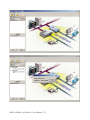
2.1 Understanding EDG-4508/4516(R)+ Modules
EDG-4508(R)+ and EDG-4516(R)+ are advanced Ethernet data gateway
units. They extend traditional COM ports of a PC to Ethernet access.
Through Ethernet networking, users can control and monitor remote
serial devices and equipment over LAN or WAN. Since EDG-4508(R)+
and EDG-4516(R)+ are connected with the TCP/IP protocol, you will
have to know fundamental facts about Ethernet networking to get the
server setup correctly. To allow for easier configuration, we provide several system configuration methods such as Configuration Utility, Web
Configuration and Console mode Configuration. More details will be
available in the following chapters.
EDG -4508(R)+ and EDG-4516(R)+ come with a virtual COM driver
that transmits all signals intact. Your existing COM-based applications
can be preserved, without in additional modification. EDG-4508(R)+
and EDG-4516(R)+ also provide various Socket modes: TCP/UDP control mode and TCP/UDP data mode. The main different of TCP and UDP
protocol is that TCP guarantees delivery of data by requiring the recipient
to send and acknowledge to the sender. UDP doesn’t require this verification.
Traditional serial devices use RS-232/422/485 interface to issue commands or transmits data to another one. Many of these devices will be
constrained by the length of wire. With the EDG-4508(R)+ and EDG4516(R)+, you are now able to communicate with each other via Internet.
Even more, you can connect any networking device dynamically.
EDG-4508(R)+/4516(R)+ User Manual 6
2.1.1 Virtual COM Port Mode
EDG series provide a virtual COM driver that works on Windows NT/
2000/XP systems. This driver establishes a transparent connection
between Host and serial devices. The driver will be installed on your
computer automatically while you install COM port mapping utility. You
have to use COM port mapping utility to configure the mapping between
the EDG serial ports and local COM ports on the host computer.
2.1.2 Data Mode
In Data mode, EDG-4508(R)+ and EDG-4516(R)+ can establish the a
TCP connection to a pre-defined host computer or device while serial
data arrives. EDG-4508(R)+ and EDG-4516(R)+ will terminate the
connection by the setting of Data Idle Timeout. This operation mode
supports 4 simultaneous connections. The Data mode provides a certain
amount of transparence and flexibility in transmitting data between
devices. If you wan to transmit data to any networking device from serial
device directly, data mode is a very perfect selection.
In data mode, the data from the serial port of one EDG-4508(R)+ and
EDG-4516(R)+ can be automatically sent to the other networking device,
without the need for an intermediate PC. Thus, serial devices will be no
longer bundled with operation system and behave like network devices to
send /receive data via Ethernet.
2.1.3 Control Mode
In controlling mode, the EDG-4508(R)+ and EDG-4516(R)+ presents a
modem interface to the attached serial device: it accepts AT-style modem
commands to connect / disconnect to other networking device. If you
want serial device running application program to connect/disconnect to
different devices by request, you can use controlling mode.
The controlling mode provides three modem AT-style commands. The
serial devices can use these commands to control EDG-4508(R)+ and
EDG-4516(R)+ to connect or disconnect to remote networking device.
Thus, intelligent serial devices such as stand-alone PLC will send /receive
data to/from devices one by one via Ethernet.
7
Chapter 2
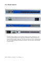
2.2 Panel Layout
Default Setting Button: press Default Setting button continuously and
press the Reset button for to load factory defaults. This will cause the
status LED to blink on and off. The factory defaults will be loaded while
the LED stops blinking and buzzer buzzed. You can release the Default
Setting button.
EDG-4508(R)+/4516(R)+ User Manual 8
2.3 Connecting Hardware
This section introduces how to connect EDG-4508(R)+ or EDG4516(R)+ to serial devices for first time.
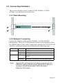
2.3.1 Rack Mounting
2.3.2 Network Connection
Connect the Ethernet cable to EDG-4508(R)+ or EDG-4516(R)+
Ethernet port. There are 2 LED indicator located on front panel to show
the Ethernet status. If the cable is connected correctly, the LAN LED will
indicate a valid connection to the Ethernet in the following ways:
LED
Status
Description
Speed
Green
100M bps
Off
10M bps
Off
No Ethernet data being received or transmitted
Blinking
Ethernet data being received/transmitted
Link/Active
Note
Speed LED will keep the last status even though the
Ethernet cable is disconnected. While EDG reboot or
re-plug in the Ethernet cable, EDG will detect
Ethernet LAN speed.
9
Chapter 2
2.3.3 Power Supply Connection
Connect EDG-4508(R)+ or EDG-4516(R)+ AC power line with its AC
connector. If the power is properly supplied, you can turn on the power
switch and the Power LED will show a green color.
2.3.4 DI/O Connection
EDG-4508(R)+/4516(R)+ User Manual 10
2.3.5 Serial Port Connection
Connect the serial data cable, OPT1A or OPT1D, between EDG series
and the serial devices.
LED
Status
Description
Tx (Port N)
N= 1~8/16
Blinking
Serial port data being transmitted
Off
No data being transmitted
Rx (Port N)
N= 1~8/16
Blinking
Serial port data being received
Off
No data being received
2.3.6 Console Port Connection
Connect to Consol port using directly cable with DB9 connector. Refer to
Chapter 6 for details.
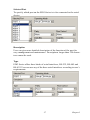
2.3.7 Ordering Information
EDG-4508+
8-port RS-232/422/485 to Ethernet Data Gateway with Front Wiring
EDG-4508R+
8-port RS-232/422/485 to Ethernet Data Gateway with Rear Wiring
EDG-4516+
16-port RS-232/422/485 to Ethernet Data Gateway with Front Wiring
EDG-4516R+
16-port RS-232/422/485 to Ethernet Data Gateway with Rear Wiring
Communication Cable RJ48 to DB9 30cm (OPT-1D)
30 cm RJ48 to DB9 M-Type RS-232/422/485 Cable
Communication Cable RJ48 to DB9 1m (OPT-1A)
1m RJ48 to DB9 M-Type RS-232/422/485 Cable
Terminal Connector (1654909900)
Terminal Connector for Test Usage
11
Chapter 2
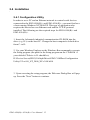
2.4 Installation
2.4.1 Configuration Utility
In order to use a PC and an Ethernet network to control serial devices
connected to the EDG-4508(R)+ and EDG-4516(R)+, you must first have
a host running Windows NT/2000/XP. This type of application also
requires the host to have an Ethernet card and the TCP/IP protocol
installed. The following are the required steps for EDG-4508(R)+ and
EDG-4516(R)+.
1. Insert the Advantech industrial communication CD-ROM into the
drive (e.g. D:\) on the host PC. Change the host computer's default drive
from C: to D:
2. Use your Windows Explorer or the Windows Run command to execute
the Setup program (the path for the Setup program on the CD-ROM if
your default CD drive is D: should be):
D:\Device Server(EDG)\Utility&Driver\EDG COMPort Configuration
Utility\V2.xx\98_NT_2000_XP v2.00 b014
3. Upon executing the setup program, the Welcome Dialog Box will popup. Press the "Next" button to continue.
EDG-4508(R)+/4516(R)+ User Manual 12
4. Carefully read the Software License Agreement, and press "Yes" to
continue.
13
Chapter 2
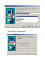
5. The Setup program will specify a default installation path, C:\Program
Files\Advantech\EDG COMPort Utility.
6. In this step, you may select a specific program folder or just use the
default setting and press "Next".
EDG-4508(R)+/4516(R)+ User Manual 14
7. After setup has copied all program files to your computer, click the
<Finish> button to finish the installation.
15
Chapter 2
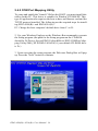
2.4.2 COM Port Mapping Utility
To setup and enable the Virtual COM on the HOST, you must install this
utility on this PC. This driver is suitable for Window NT/2000/XP. This
type of application also requires the host to have an Ethernet card and the
TCP/IP protocol installed. The following are the required steps for installing EDG-4508(R)+ and EDG-4516(R)+.
PC. Change the host computer's default drive from C: to D:
2. Use your Windows Explorer or the Windows Run command to execute
the Setup program (the path for the Setup program on the CD-ROM
should be D:\Device Server(EDG)\Utility&Driver\EDG COMPort Mapping Utility\2000_XP WDM v2.00 b206, if your default CD-ROM drive
is D: ).
3. Upon executing the setup program, the Welcome Dialog Box will popup. Press the "Next" button to continue.
EDG-4508(R)+/4516(R)+ User Manual 16
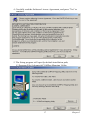
4. Carefully read the Software License Agreement, and press "Yes" to
continue.
5. The Setup program will specifya default installation path,
C:\Program Files\Advantech\COMPort Mapping Utility.
17
Chapter 2
6. In this step, you may select a specific program folder or just use the
default setting and press "Next".
7. After setup has copied all program files to your computer, click the
<Finish> button to finish the installation.
EDG-4508(R)+/4516(R)+ User Manual 18
CHAPTER
3
2
Configuration
Chapter 3 Configuration
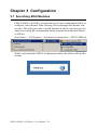
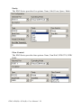
3.1 Searching EDG Modules
EDG-4508(R)+/4516(R)+ provides an easy-to-use configuration utility to
configure your Ethernet Data Gateway Device through an Ethernet connection. The utility provides a search function to show your device(s) by
simply executing the configuration utility program from the Start Menu
as follows.
Start Menu -> All Program ->Advantech eAutomation -> EDG COMPort
While you launch the EDG II configuration utility, the utility will load the
setting.
EDG-4508(R)+/4516(R)+ User Manual 20
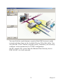
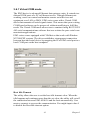
You can click the search button to search all the EDG device(s) on the
network and show them on the Available Devices Tab of the utility. You
can click the “Close” button to stop the search. From here you can easily
configure various parameters for TCP/IP configuration.
(In this example, the system finds the Ethernet Data Gateway device
EDG-4516R+ in a local network)
21
Chapter 3
EDG-4508(R)+/4516(R)+ User Manual 22
You can click on the device name to show the features of the specific
device. Click on the "+" before the model name (e.g. EDG4516(R)+),and the utility will expand the tree structure to show the individual device name. Click on the “-“ before the model name (e.g. EDG4516(R)+), and the utility will collapse the structure.
You may click the button, and the utility will expand all tree structure to
show the individual device name. You might click button to collapse all
tree structure.
For Example, EDG Configuration Utility shows "EDG-000102FFFF06"
after expanding the tree structure.
Note
The EDG series default device name is "MAC ID". In
this case, the device name "EDG-000102FFFF06"
means the device "MAC ID" is "00 01 20 FF FF
06".You can change the default device name in System Tag of Device Properties.
Note
Please reserve TCP port 5202 in your network ,Configuration will use this port to communicate with EDG
series.
23
Chapter 3
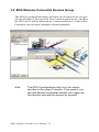
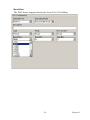
3.2 EDG Modules Connected Devices Group
This EDG II configuration utility will allow you to add a device via specifies the IP address. You can click ‘New’ button to add a device. And then
the EDG device will be shown on the ‘Connected Devices’ of the utility.
From here you can easily configure various parameters.
Note
The EDG II configuration utility only can search
devices on the same IP domain. If you want to connect the devices on another domain, you might use
this function and add the devices by yourself.
EDG-4508(R)+/4516(R)+ User Manual 24
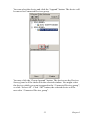
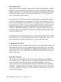
You can select the device and click the “Append” button. The device will
be moved to Connected Devices group.
You may click the “Group Append” button. The devices on the Devices
Survey panel will be showed on the selected window. You might select
the devices which you want to append to the “Connected Devices group”,
or click “Select All”. Click “OK” button, the selected device will be
moved to “Connected Devices group”.
25
Chapter 3
3.2.1 Deleting Devices
You can select the device on Connected Devices group and click “Delete”
button. The device will be deleted. You may click “Search” button and
find the device again.
EDG-4508(R)+/4516(R)+ User Manual 26
3.2.2 Connected Devices Group Functions
While you move the device(s) to Connected Devices group, you can use
these functions
• Lock device
• Grouping Allocate
• Download firmware
• EDG II configuration utility check the device(s) automatically. Connected – online, Disconnected – offline
• The utility will record these devices on Connected Devices group and
will connect and check these devices again while the utility will be relaunched.
3.3 Locking & Unlocking Devices
The EDG II configuration utility provides Lock and Grouping Lock function to secure the device(s). You can modify the password one by one on
the “Security Configuration” tab. There is only one password in the EDG4516(R)+ and EDG-4508(R)+. You can use Configuration utility, Web
Configuration, and Console to modify this password and disable the
security control.
27
Chapter 3
Note
Don’t input any character on the password field and
save. The security control is disabled.
You also use the “Grouping Lock” button to modify the password while
the devices are on “Connected Devices group”.
EDG-4508(R)+/4516(R)+ User Manual 28
While you click “OK” button, the password will be updated to device.
You should click “Reset” button, the module will move this data to Flash
memory and restart.
Note:
You might finish all setting and click "Apply" to enable
the modification in the moment; otherwise the setting
will disappear while the device restarts.
You can click the “Un-lock” button and select the devices you want to
unlock.
29
Chapter 3
You also select the device and right click “Mouse button”. Input the password and unlock the device.
EDG-4508(R)+/4516(R)+ User Manual 30
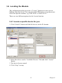
3.4 Locating the Module
The configuration utility provides a "Locate" function to assist you in
finding a specific device. You can select the EDG Series as a group or just
select one specific module, e.g. EDG-4508+ or EDG-4516+.
There are two different options for the Locate function
3.4.1 Locate a specific device for you
1. Click “Search” button and find all devices on the IP domain.
2. Select the device on the “Available Devices” Tab and click “Locate”
button.
3. The device buzzer sound.
4. Click “Stop” to stop.
31
Chapter 3
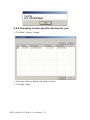
3.4.2 Grouping Locate specific devices for you
1. Click the “Locate” button
2. Select the devices which you want to locate.
3. Click the “Stop”
EDG-4508(R)+/4516(R)+ User Manual 32
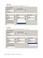
3.5 Device System Configuration
The EDG II configuration utility only searches for EDG-4508(R)+ and
EDG-4516(R)+ on the local network, and cannot search beyond a router
or gateway. Make sure that the EDG-4508(R)+ or EDG-4516(R)+ you
want to monitor resides in the same local network segment as the host PC.
You might use “New” function to add the device by yourself.
Device Name
The configuration utility provides a default name for device to distinguish
a specific EDG Series from other EDG Series. You can update the default
device name based on your application. Names longer than 32 characters
cannot be used. It is best to choose a name you can remember.
Device Description
This field is to record the function, application and other information for
each EDG Series device in more detail for easy management and maintenance. You are allowed to describe in your own words. Names longer
than 127 characters cannot be used.
33
Chapter 3
Firmware Version
In this field, the configuration utility represents the firmware version of
the EDG Series. You might need to refer to the firmware version to determine functions available on the EDG Series device. In case of problems
that might concern the firmware version, please provide the firmware version number to our Customer Service.
Network Configuration Ethernet
Select the Ethernet that you want to configure.
MAC Address
The MAC address is for the local system to identify and locate each EDG
series. This MAC address is already set before delivery from factory,
hence no need for further configuration.
IP address, Subnet Mask, Default Gateway
The IP address identifies your EDG device on the global network. Each
EDG device has the same default IP address 10.0.0.1. Obtain a specific IP
address from your network administrator and then configure each EDG
device with an individual IP address, related Subnet Mask and Gateway
Setting.
EDG-4508(R)+/4516(R)+ User Manual 34
Note
EDG devices do not support auto IP address configured by DHCP server.
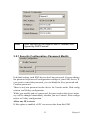
3.5.1 Security Configuration -Password Modify
In default setting, each EDG device don’t has password. You can change
the password to protect all configuration settings of your EDG device. If
you want to cancel the password, you can blank the New password and
Confirm password.
There is only one password on the device for Console mode, Web configuration, and Utility configuration.
While you modify and save password, the password on the device memory will be changed immediately whether you use Console, Web configuration, or Utility configuration.
Allow any IP to access
If this option is enabled, all PC can access data from this EDG.
35
Chapter 3
The specified IP which can access
Enabled this option, you might limit at most 32 PCs to access data from
this EDG.
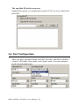
3.6 Port Configuration
There are three operation modes for EDG-4516(R)+ and EDG-4508(R)+,
Virtual COM mode, Data mode, and Control mode. You can configure
mode for individual ports.
EDG-4508(R)+/4516(R)+ User Manual 36
Selected Port
To specify which port on the EDG Series is to be connected to the serial
device.
Description
User can give more detailed description of the function of the port for
easy management and maintenance. Descriptions longer than 128 characters cannot be used.
Type
EDG Series offers three kinds of serial interfaces, RS-232, RS-485 and
RS-422. User can use any of the three serial interfaces according to user’s
requirements.
37
Chapter 3
Parity
The EDG Series provides five options: None, Odd, Even, Space, Mark.
Flow Control
The EDG Series provides four options: None, Xon/Xoff, RTS/CTS, DTR/
DSR.
EDG-4508(R)+/4516(R)+ User Manual 38
Baud Rate
The EDG Series supports baud rates from 50 to 230,400bps.
39
Chapter 3
Data Bits
The EDG Series provides four options: 5, 6, 7 or 8.
Stop Bits
The EDG Series provides three options: 1, 1.5 or 2.
EDG-4508(R)+/4516(R)+ User Manual 40
3.6.1 Virtual COM mode
The EDG device is advanced Ethernet data gateway units. It extends traditional COM ports of a PC to Ethernet access. Through Ethernet networking, users can control and monitor remote serial devices and
equipment over LAN or WAN. EDG series come with a Virtual COM
driver that transmits all serial signals intact. This means that your existing
COM-based software can be preserved, without modifying to fulfil the
needs. The Virtual COM mode allows user to continue using RS-232/422/
485 serial communications software that was written for pure serial communication applications.
EDG series comes equipped with COM driver that work with Window
NT/2000/XP systems. The driver establishes a transparent connection
between host and serial device by mapping the IP of EDG serial port to a
local COM port on the host computer.
Host Idle Timeout
The utility allows the user to set the host idle timeout value. When the
idle happens and continues more than the set value, the utility will cut off
the connection between EDG-4508/16 and the host automatically. User
must re-connect to recover the communication. You might input value 0
to disable the Host Idle timeout option.
41
Chapter 3
Note
While you disable the Host Idle option, the EDG will
not cut off the connection. If Host loses the connection with EDG and the Host Idle option is disabled,
Host will not connect to EDG again.
3.6.2 Data Mode
EDG-4516(R)+ and EDG-4508(R) can be Data server or Data client
either. Both operations support TCP and UDP protocol. The EDG4516(R)+ and EDG-4508(R) makes your serial devices behave just like
networking devices. You can issue commands or transmit data from serial
devices, which connected to EDG-4516(R)+ and EDG-4508(R), to any
devices that are connected to the Internet.
EDG-4516(R)+ and EDG-4508(R)+ allows most 4 host PC accessing
data simultaneously via polling networking architecture. You can use it
according to your application. If you want to access the EDG-4516(R)+
and EDG-4508(R), you must ascertain your application software supports
standard networking application programming interface (API) such as:
WinSock Socket.
You might select Data mode and setup port attributes
EDG-4508(R)+/4516(R)+ User Manual 42
Protocol
EDG-4516(R)+ and EDG-4508(R)+ provides TCP/IP and UDP two protocols. In settings, you can choose either TCP mode or UDP mode
according to your application.
43
Chapter 3
Data Listen Port
The TCP(UDP) port number represents the source port number , and the
number is used to identify the channel for remote initiating connections.
Range: 1024-65533. If an unknown caller wants to connect to the system
and asks for some services, they need to define the TCP(UDP) port to
carry a long-term conversation.
Each node on a TCP/IP network has an IP address, and each IP address
can allow connections on one or more TCP port. The well known TCP
port are those that have been defined; for example, port 23 is used for Telnet connections. There are also custom sockets that users and developers
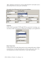
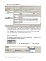
define for their specific needs. The default TCP (UDP) port of EDG4516(R)+ and EDG-4508(R)+ is 5200. The example initial 5200 is System Port, and 5201 is Data Port. But users can adjust them by one's preference or application.
Each port has its own data listen port to accept connected request of other
network device. So, the data listen port can’t be set the same value. You
can transmit/receive data to/from device via the data listen port.
Command Listen Port
Each port has its own command listen port to accept connected request of
other network device. So, the command listen port can’t be set the same
value. You can use ‘AT command’ to change the port setting via the command listen port. The Command Listen Port must be different from the
Data Listen port.
Data Idle Timeout
The default is 60 seconds. If you want to keep connection continually,
you can key-in “0”. Data idle Time is the time period in which the device
waits for data. If the EDG-4516(R)+ and EDG-4508(R)+ does not
receive data over an established idle time, the EDG-4516(R)+ and EDG4508(R)+ will disconnect temporarily. When the data comes to the EDG4516(R)+ and EDG-4508(R)+, it will reconnect automatically. Users do
not need to reconnect.
EDG-4508(R)+/4516(R)+ User Manual 44
Peer Number
Set the number of network device which you want to connect.
IP Address
IP address of network devices which you want to connect.
Port
Another TCP port of network devices which you want to connect.
3.6.3 Control Mode
In controlling mode, the EDG-4516(R)+ and EDG-4508(R)+ present a
modem interface to the attached serial device: it accepts AT-style modem
commands to connect / disconnect to other networking device. If you
want serial device running application program to connect/disconnect to
different devices dynamically, you can use controlling mode.
The controlling mode provides three modem AT-style commands. The
serial devices can use these commands to control EDG-4516(R)+ and
EDG-4508(R)+ to connect/disconnect to remote networking device.
45
Chapter 3
Thus, intelligent serial devices such as stand-alone PLC will send /receive
data to/from devices one by one via Ethernet.
You might select Data mode and setup port attributes
Protocol
EDG-4508/16 provides TCP/IP and UDP two protocols. In settings, you
can choose either TCP mode or UDP mode according to your application.
Data Listen Port
Each port has its own data listen port to accept connected request of other
network device. So, the data listen port can’t be set the same value. You
can transmit/receive data to/from device via the data listen port.
EDG-4508(R)+/4516(R)+ User Manual 46
Command Listen Port
Each port has its own command listen port to accept connected request of
other network device. So, the command listen port can’t be set the same
value. You can use ‘AT command’ to change the port setting via the command listen port.
Data Idle Timeout
The default is 60 seconds. If you want to keep connection continually,
you can key-in “0”.
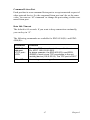
The following commands are available for EDG-4516(R)+ and EDG4508(R)+.
Command
Function
ATDT<IP
address>
<TCP port>
<CR>
“Forms a TCP connection to the specified host.
Ex: ATDT 192.0.55.22:5201
In above example, the EDG-4516(R)+ and EDG4508(R)+ forms a raw TCP connection to the networking device (192.0.55.22). The TCP port is 5201.”
ATA <CR>
Answering an incoming call
47
Chapter 3
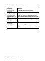
The following table illustrates the response.
Command
Function
<LF><CR> OK
<LF><CR>
Commands are executed correctly
<LF><CR> CONNECT <LF><CR>
Connect to other device
<LF><CR> RING
ddd.ddd.ddd<LF><
CR>
Detect the connection requesdt from other
device, which IP address is ddd.ddd.ddd.ddd.
<LF><CR> DISCONNECT
<LF><CR>
Disconnect from other device
<LF><CR> ERROR
<LF><CR>
Incorrect commands
<LF><CR> FAIL
<LF><CR>
If you issu an ATDT command and can not
connect to the device, it will response
“FAIL”.
EDG-4508(R)+/4516(R)+ User Manual 48
3.7 Monitor and Event Configuration
3.7.1 Device Status
EDG Configuration utility II provide an excellent function to monitor the
virtual serial port status. User can check the serial port health.
Refresh
Update port status manually when you click ‘Start’ button.
Continue
Update port status automatically every 10 seconds unless you click ‘Stop’
button.
49
Chapter 3
3.7.2 Event setting
EDG-4508(R)+/EDG-4516(R)+ provide 4 events with comparison and
different server IP and Port. The event will be activated when any one of
DI signals that you specified meets the ‘Action’ option. The event will be
monitored on the Host and port of your assignment.
Event Setting
Specify which event of the device is to be set.
Action
There are three options: L->H, H->L or Change.
L->H: Low to High
H->L: High to Low
Change: status change
Trigger
Specify which DI you want to monitor.
Server IP Address
IP address of network device which you want to connect.
TCP Port
TCP port of network device which you want to connect.
EDG-4508(R)+/4516(R)+ User Manual 50
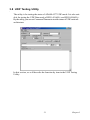
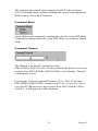
3.8 UDP Testing Utility
The utility is for testing the status of ADAM-4577 UDP mode. It is also suitable for testing the UDP Data mode of EDG-4516(R)+ and EDG-4508(R)+.
By the utility, you can set Command Timeout to test the status of UDP network
architecture.
In this section, we will describe the function by item in the UDP Testing
Utility.
51
Chapter 3
Target Device & UDP Port
You can set Target Device IP Address according to Network IP Address in
Configuration Utility. And UDP Port is depended on Setting Listen on UDP
Port in Configuration Utility. “UDP Port” value is equal to “Listen on UDP
Port” value plus one. For Example: If your Listen on UDP Port is setting
5300, UDP Port in UDP Testing Utility must set 5300.
Command Format
This option have two choices, one is ASCII and another is HEX. This will
decide Command blank what to display.
You can choose None, CR, LF, CR+LF to test.
EDG-4508(R)+/4516(R)+ User Manual 52
The command edit control can be inputted in ASCII code ast choose
ASCII Command Forma, and the command edit control can be inputted in
HEX format as choose HEX Coomand.
Command Mode
Single Mode means command is running only one time to test UDP Mode.
Command is running repeatedly to test UDP Mode as you choose Repeat
Mode.
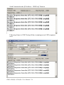
Command Timeout
The "Timeout" is the Host PC waiting time from
EDG-4508(R)+/EDG-4516(R)+, in this period Host PC doesn’t receive any
response from EDG-4508(R)+/EDG-4516(R)+, it will display “Timeout”
as setting time is over.
For Example, if setting Command Timeout is 12 sec., Host PC will wait
EDG-4508(R)+/EDG-4516(R)+ response until 12 sec. is over. As 12 sec. is
over, Host PC did not receive any response from EDG-4508(R)+/EDG4516(R)+ , it will appear the following frame :
53
Chapter 3
Send Command to the [IP Address : UDP Port] Timeout
Following Frame is UDP Testing Utility is running test as UDP responses
well.
EDG-4508(R)+/4516(R)+ User Manual 54
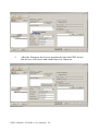
3.9 Updating EDG Firmware
Advantech continually upgrades its firmware. You can use the download
function located on the COM Port Configuration utility to carry out the
upgrade procedure. Please access www.advantech.com to download the
required file and then follow these instructions.
You have to move the device to Connected Device group, and then you
can use download firmware function
1.
Click on the Upgrade FW button
2.
Locate and select the firmware that you want to download.
55
Chapter 3
3.
After the firmware have been downloaded into the EDG device,
this device will reboot and enable the new firmware.
EDG-4508(R)+/4516(R)+ User Manual 56
4
CHAPTER
2
Port Mapping Utility
Chapter 4 Port Mapping Utility
4.1 Overview
The purpose of the port mapping utility is to help you manage all ports on
one Windows NT/2000/ME/XP platform. The utility displays three types
of ports: used ports, unused ports and EDG ports. Please follow the Virtual COM port setting steps.
4.2 Virtual COM Port Settings
1. Click "+" at "Unused Ports" to expand the unused port lists, and select
the port that you want to configure.
EDG-4508(R)+/4516(R)+ User Manual 58
2. Click the 'Add' button to assign a COM port to an EDG device. You
might click 'Add All' button to assign the COM ports the EDG device.
The COM ports number depends on the model of installed device that
you selects.
Module of Installed Device
You can choose between all connected EDG devices. In this example,
EDG-4516(R)+ was chosen.
IP Address of Installed Device
Enter the IP address you assigned prior.
Port of Installed Device
Choose the port where you want to setup: 8 ports for EDG-4508(R)+ and
16 ports for EDG-4516(R)+.
59
Chapter 4
Properties (Auto Reconnect Function)
Sometimes, the connection between EDG device and HOST is interrupted by network traffic or powered-off by accident. In such a situation,
the host have to reconnect to EDG device.
The function "Auto-reconnect" is for this purpose, If the EDG device
loses the connection to its host, the VCOM driver will try to re-establish
the connection while the HOST AP access the VCOM port. The driver
DO NOT re-establish the connection automatically. When the connection
is working again, the host's commands will be automatically received by
the EDG Series again. Reconfiguration is not necessary, so this function
enhances the reliability of the system.
if the function is disabled, the connection can not be re-established again
unless the VCOM driver or HOST is restarted.
Memo
You can add a description to the port setting if necessary.
Add
Click here to add a single port setting to your specification.
Add All
You can assign all ports to follow current settings by clicking the "Add
All" button. This is more convenient than adding ports individually. For
this example, we have selected COM21 and made all necessary settings
for Port 1 of EDG-4516+. After clicking on the "Add All" button, the
COM Port Mapping Utility will assign the COM21 ~ COM36 mapping to
Port 1 ~ Port 16.
EDG-4508(R)+/4516(R)+ User Manual 60
(COM21 is mapping to Port 1 of EDG-4516+)
(COM22 is mapping to Port 2 of EDG-4516+)
Note
If you assigned a different COM port to the
same EDG series module port, the following
dialog box will remind you.
61
Chapter 4
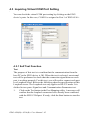
4.3 Inquiring Virtual COM Port Setting
You can check the virtual COM port setting by clicking on the EDG
device’s ports. In this case, COM11 is assigned to Port 1 of EDG-4516+.
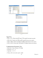
4.3.1 Self Test Function
Test
The purpose of this test is to confirm that the communication from the
host PC to the EDG device is OK. When the test is selected, an external
test will be performed to check that the connection signal between each
port is working properly. For this test, you will need to connect each port
to a Loopback tester. Refer to the following chart for specifications of this
Loopback tester. The Loopback test only applies to RS-232 mode. It is
divided in two parts: Signal test and Communication Parameters test.
1.
Click on the Test button in the Port Mapping utility. A message will
confirm that the loopback connector have already been connected
with the EDG COM port. If ready, click the Start button to start the
test.
EDG-4508(R)+/4516(R)+ User Manual 62
Test Fail (Without Loopback Connector)
Test ok
Signal Test
• RTS->CTS: Checks the RTS and CTS signals between two ports.
• DTR->RI: Checks the DTR and RI signals between two ports.
• DTR->DSR: Checks the DTR and DSR signals between two ports.
• DTR->DCD: Checks the DTR and DCD signals between two ports.
Communication Parameters Test
• Baud rate: From 50 bps to 230 kbps
• Data bits: 5, 6, 7, 8
• Stop bits: 1, 1.5, 2
• Parity: odd, even, none, space, mark
63
Chapter 4
2.
Click the OK button to return to the port mapping window. All the
ports in the EDG Series are tested ok.
Delete
You can delete Port Mapping Setting by clicking the button.
Apply
If any changes are made, please press the button to confirm your
modifications.
Exit
If you want to quit the utility, you might click < Exit > button or <X> on
the right top of this window. A new enhancement is implemented from
version 1.40 Build137. If any changes are made in the COM Port Mapping setting, your changes will work while you exit COM Port Mapping.
Sometime, the system reboot requirement might show up.
Note
If you change the COM port setting and the COM is
used by AP, the COM Port Mapping utility will crash
and you might get the ‘Blue Screen’. This is
because the COM resource is occupied by OS
system, COM port Mapping utility try to remove it
and unauthorized accessing occur.
EDG-4508(R)+/4516(R)+ User Manual 64
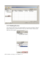
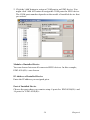
4.3.2 Save the Configuration
If you want to save or recover the configuration, you can select the
"Import/Export" items.
1.
a. Select "File"
b. Select "Import" or "Export".
2.
Save or open the configurations
65
Chapter 4
EDG-4508(R)+/4516(R)+ User Manual 66
CHAPTER
5
2
Web-Based
Configuration
Chapter 5 Web-Based Configuration
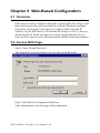
5.1 Overview
EDG devices can be configured through a web interface. By using a standard web browser, the same procedure as with the Windows configuration utility can be used. In the browser’s address field, enter the IP
Address of your EDG device. The default IP setting is 10.0.0.1, but you
should use the IP which you have previously assigned for this device.
Once the IP is entered, you will be presented with the following windows.
5.2 Access Web Page
Step 1. Enter ID and Password
The default ID and password is root, key this into both fields..
Step 2. Web Based Configuration Welcome
After authorization, the first page will be displayed.
EDG-4508(R)+/4516(R)+ User Manual 68
You can change the Device Name and Device Description on this page.
Press ‘Save’ to store the settings.
69
Chapter 5
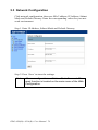
5.3 Network Configuration
Click network configuration, there are: MAC address, IP Address, Subnet
Mask and Default Gateway. Enter the corresponding values for your network environment.
Step 1. Enter IP Address, Subnet Mask and Default Gateway
Step 2. Press ‘Save’ to store the settings.
Note:
All new configurations will take effect after reset. The
reset function is located on the main menu of the Web
Configuration.
EDG-4508(R)+/4516(R)+ User Manual 70
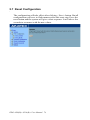
5.4 Port Configuration
Under port configuration – Port’s Mode, you can setup the mode for individual ports. There are three modes Virtual COM mode, Data mode, and
Control mode. While you select VCOM mode, you also setup HOST Idle
option here.
5.4.1 Data Mode
You might refer to chapter 3.6.2 to clarify the setting.
71
Chapter 5
5.4.2 Control Mode
You might refer to chapter 3.6.3 to clarify the setting.
5.4.3 Port UART setting
You can as sign the Type, Parity, Flow Control, Baud Rate, Data Bits, and
Stop Bits.
You might enable the ‘Set all ports parameter like Port 1’ and others setting will set as same as Port 1.
EDG-4508(R)+/4516(R)+ User Manual 72
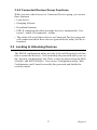
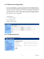
5.5 DI/O Event Configuration
In event configuration, you can assign a DI event by enabling the check
box and choosing the optimized action mode, Server IP and TCP Port for
the active event. You can setup 4 events with comparison and different IP
and Port. The event will be activated when any one of DI signals that you
specified meets the ‘Action’ option. The event will be monitored on the
Host and port of your assignment.
Action option:
L->H: Low to High
H->L: High to Low
Change: status change
5.6 Change Password
You can modify the password.
73
Chapter 5
5.7 Reset Configuration
The configuration will take effect after clicking < Save> button. But all
configurations will save to flash memory after this reset step. Press the
reset button and the system will give a reset response. It will take a few
seconds to reconnect with the new values.
EDG-4508(R)+/4516(R)+ User Manual 74
6
CHAPTER
2
Console Configuration
Chapter 6 Console Configuration
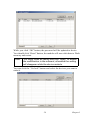
6.1 Overview
The purpose of the Console Configuration is to help you manage your
device in console mode. One of the main functions of the console mode is
to change the web configuration login password. You can use terminal
software like Hyper Terminal, Telix and other related terminal software.
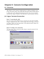
6.2 Hyper Terminal Connection
Step 1. Connecting the cable
You can connect to the EDG device’s console port with a RS-232 DB9
M-type communication cable, with the other end connecting to the host’s
serial port. Make sure the connection is OK and then run the Hyper Terminal Program on your host.
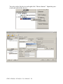
Step 2. Creating a new connection
You can create a new connection and assign a connection name for the
console configuration.
EDG-4508(R)+/4516(R)+ User Manual 76
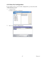
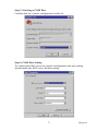
Step 3. Selecting a COM Port
Confirm that the console configuration works ok.
Step 4. COM Port Setting
To connect the EDG series for console configuration, the port setting
should match the EDG series' default setting.
77
Chapter 6
Console Configuration Default Setting
Baud Rate: 57600
Data Bits: 8
Parity: None
Stop Bits: 1
Flow Control: None
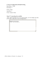
Step 5. Connecting Successfully
After connecting the device in console mode, you can simply type the
password to entry the consol configuration.
EDG-4508(R)+/4516(R)+ User Manual 78
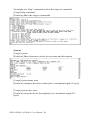
6.3 Command List
Command
Function
system
Show or configure device name and information
port
Show or configure ports information
mvcom
Show or configure all port mode and mode information
mctrl
Show or configure port mode and mode information
mdata
Show or configure port mode and mode information
pmode
Show port mode
event
Show or configure the event status and information
net
Displays or configure the net configuration
password
Set password
reboot
Write settings to flash memory and reboot the system immediately
save
Save the settings right now.
exit
Terminate shell session
help
Display help information of command list
<TAB><TAB
>
Display help information of command list
Help
You might type "help" command or press <Tab> twice to show the Supported Command Lists.
[Usage] Help
[Function] Display help information of command lit
79
Chapter 6
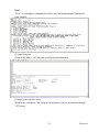
You might use “help” command to show the usage of command.
[Usage] help command
[Function] Show the usage of command.
System
[Usage] system
[Function] Show firmware version, device name and description
[Usage] system name xxxx
[Function] configure the device name [xxxx: maximum length 31 bytes]
[Usage] system desc xxxx
[Function] setup the device description [xxxx: maximum length 127
bytes]
EDG-4508(R)+/4516(R)+ User Manual 80
Port
‘Port’ is a complex command to show port information and configure
port setting.
[Usage] port nn
[Function] Show “nn”nd port or all ports information
[Usage] port nn desc xxxx
[Function] configure “nn”nd port description, [xxxx: maximum length
127 bytes]
81
Chapter 6
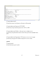
[Usage] port nn type 232|422|485 flow 0|1|2|3
[Function] setup serial type and flow control
Flow 0: None
Flow 1: XOn/Xoff
Flow 2: RTS/CTS
Flow 3: DTR/DSR
[Usage] port nn baud xx parity n|e|o|m|s data 5|6|7|8 stop 1|1.5|2
[Function] setup serial baud rate, parity check, data bit, and stop bit.
Acceptable baud rate setting:
Parity n: None parity
Parity e: Even parity
Parity o: Odd parity
Parity m: Mark parity
Parity s: Space parity
[Usage] port nn mode vcom|ctrl|data
[Function] configure serial port as virtual COM mode, Control mode, and
Data mode.
mvcom
Show and setup COM ports mode
EDG-4508(R)+/4516(R)+ User Manual 82
[Usage] mvcom
[Function] show all ports
[Usage] mvcom nn|all
[Function] setup “nn”nd port or all ports as Virtual COM mode.
[Usage] mvcom nn|all idleto xx
[Function] configure host idle time.
mctrl
Show and setup Control mode
83
Chapter 6
[Usage] mctrl
[Function] show port mode
[Usage] mctrl nn|all
[Function] setup “nn”nd port or all ports as Control mode.
[Usage] mctrl nn|all protocol TCP|UDP
[Function] setups transmit protocol as TCP or UDP.
[Usage] mctrl nn|all idleto x data port xxxx cmdport xxxx
[Function] setup data idle timeout, data listen port and command listen
port.
Mdata
Show and setup Data mode
[Usage] mdata
[Function] show port mode
EDG-4508(R)+/4516(R)+ User Manual 84
[Usage] mdata nn|all
[Function] setup “nn”nd port or all ports as Data mode.
[Usage] mdata nn|all protocol TCP|UDP
[Function] setups transmit protocol as TCP or UDP.
[Usage] mdata nn|all idleto x data port xxxx cmdport xxxx
[Function] setup data idle timeout, data listen port and command listen
port.
[Usage] mdata nn|all peernum 1|2|3|4 peer xxx.xxx.xxx.xxx:ppp
[Function] setup peer IP address and port for receive data.
pmode
[Usage] pmode
[Function] show port’s mode.
85
Chapter 6
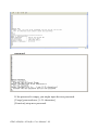
Event
[Usage] event
[Function] show the event’s status and configuration
[Usage] event nn|all trigger no|0&1&2&3 action L2H|H2L|CHG
[Function] setup the event(s)
[Usage] event nn|all server xxx.xxx.xxx.xxx:ppp
[Function] setup server IP address and TCP port.
EDG-4508(R)+/4516(R)+ User Manual 86
net
[Usage] net
[Function] show the MAC address, IP address, Subnet Mask, and default
gateway.
[Usage] net ip xxx.xxx.xxx.xxx netmask xxx,xxx,xxx,xxx gw
xxx,xxx,xxx,xxx
[Function] setup IP address and subnet mask and default gateway.
87
Chapter 6
password
If the password is empty, you might input the new password.
[Usage] password new [1~31 characters]
[Function] setup new password.
EDG-4508(R)+/4516(R)+ User Manual 88
If the password is existed, you have to input the existed password and
new password.
[Usage] password old [existed password] new [1~31 characters]
[Function] replace the existed password with new one.
89
Chapter 6
EDG-4508(R)+/4516(R)+ User Manual 90
CHAPTER
7
2
Event and DI/O
Monitoring
Chapter 7 Event and DI/O Monitoring
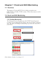
7.1 Overview
The purpose of Event and DIO Test is to help you monitor your
EDG-4508(R)+/4516(R)+ DI/DO event(s). Follow these steps to test the
DI/DO event(s).
7.2 Event and DI/O Monitoring
7.2.1 Polling Monitoring
The following screen will appear once the EVENT Tester Program is
executed. To start monitoring the Polling, enter the IP Address and press
start. The Status will change to Monitoring if you enter the correct IP of
your device.
Enter IP Address of EDG Series
Start with Idle Status
EDG-4508(R)+/4516(R)+ User Manual 92
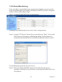
7.2.2 Event Monitoring
Once you have executed the steps in previous chapters you can use the
tester to monitor the event status with the port and IP you have assigned
before. Please follow these steps:
Step 1. Assign IP and TCP Port for monitoring
(Setting Event monitoring from Web Event Configuration)
Step 2. Assign TCP Port of Event Server and click on "Start". Event and
DIO tester will change to Monitoring Mode. Red indicator in
normal mode means Inactive and Green indicator means Active.
(Event Monitoring and no Event Active)
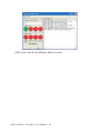
Step 3. We can activate the DI0 event; tester will show the green
indicator. Message Log will show event log with timer and event
description.
93
Chapter 7
(DI0 Active and Event Monitor Shows Green)
EDG-4508(R)+/4516(R)+ User Manual 94
7.3 Programming I/O
According the feature list, it mentioned EDG-4508+/4516+ provide the
D/I AND D/O handling function. In order to help customer to create the I/
O event handling environment. We provide a programmable I/O sample
program for customer use. After installing the EDG COM Port Utility, the
sample programs will be on the location as follow:
C:\Program Files\Advantech\EDG COMPort Utility\samples\vc\
edgevtio.
How to use the sample files?
(1) The sample programs include following file and the develop environment is based on Microsoft Visual C++.
edgevtio.cpp
edgevtio.dsp
edgevtio.dsw
edgevtio.ncb
edgevtio.opt
edgevtio.plg
mbtcp.h
(2) Compiler the sample program
(3) Run the sample program
After compiler the program and run the program, the system will
change to Server mode to trigger any D/I event and sent back to system to active the D/O event.
(4) You can modify the program and create your own event handling
process.
(5) Sample files list and description as follow:
edgevtio.cpp : Defines the entry point for the console application.edgevtio.dsp
edgevtio.dsp : Microsoft Developer Studio Project File
edgevtio.dsw : Microsoft Developer Studio Workspace File
edgevtio.ncb : Microsoft C/C++ program database
edgevtio.opt
edgevtio.plg
mbtcp.h
In this sample files, we provide the note for the parameter for programmer use.
For example:
In edgevtio.cpp file content, line 32 to line 41
95
Chapter 7
memset(&HostAddr, 0, sizeof(SOCKADDR_IN));
HostAddr.sin_family = AF_INET;
HostAddr.sin_addr.s_addr = INADDR_ANY;
HostAddr.sin_port = htons(5000);
//
|
//
+-->The TCP Port in the server application
It remarks the function of htons(n), the parameter n means the TCP Port
in server application and It helps the programmer to make his own
program easier by referencing the note we provided.
HostSock = socket(AF_INET, SOCK_STREAM, 0);
//
//
|
+-->Create the socket of TCP on the Host
It remarks the function of socket(AF_INET, SOCK_STREAM, 0), the
function of socket(var1,var2,n) means to create the socket of TCP on
Host. Programmer can also create the socket of TCP on the Host by
himself.
edgevtio.dsp
Programmers can choose the develop tools for themselves. For example,
in edgevtio.dsp file, the extension file name .dsp means Microsoft
Developer Studio Project File. Programmer can open the file as a template to create their own programs.
edgevtio.dsw
File name of edgevtio means EDG Event I/O, extension name of dsw
means it is a Microsoft Developer Studio Workspace file. This file is
necessary when you open a Developer Studio Project and we make a
warning note in file to reminder you not to modify or delete this related
workspace file.
EDG-4508(R)+/4516(R)+ User Manual 96
mbtcp.h
File name of mbtcp means Modbus TCP; we provide the easier definition
of necessary parameter. For example,
#define MODBUSTCPMAXMSGLENGTH
288
#define MODBUSTCPMSGHDRLENGTH
6
typedef struct __MODBUSTCPMSG {
unsigned short wTransactionId;
unsigned short wProtocolId;
unsigned char byteMsgLenHigh;
unsigned char byteMsgLenLow;
unsigned char Data[2];
} TMODBUSTCPMSG;
MODBUSTCPMAXMSGLENGTH
MODBUS TCP Max Message Length
MODBUSTCPMSGHDRLENGTH
MODBUS TCP Message Header Length
* The programming I/O sample programs are for programmer's reference
to make the event I/O program for their own environment. Programmers can open the file as a template file to make a new project of event.
97
Chapter 7
EDG-4508(R)+/4516(R)+ User Manual 98
A
APPENDIX
2
Pin Assignments
Appendix A Pin Assignments
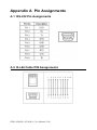
A.1 RS-232 Pin Assignments
A.2 RJ-48 Cable PIN Assignments
EDG-4508(R)+/4516(R)+ User Manual 100
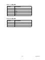
A.2.1 1. RS-422
Pin No.
Description
1
Tx-
4
Tx+
5
GND
7
Rx+
9
Rx-
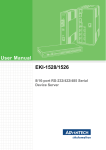
A.2.2 2. RS-485
Pin No.
Description
1
Data-
4
Data+
5
GND
101
Appendix A
EDG-4508(R)+/4516(R)+ User Manual 102