1
,..........~~--------~
-
-
CQD-440/443
High Performance Q-bus
FAST SCS!-2 Smart H~st Adapter
User's Manual
~U~CMD
§
ETECHNOLOGr~~~~~
~/NC.
Q
\
i
MAN-000440-000
Rev. 1.0
CQD-440/443
High Performance Q-bus
FAST SCS!-2 Smart Host Adapter
User's Manual
CMD Technology, Inc.
] Vanderbilt
Irvine, CA 92718
(7] 4) 454-0800
Copyright
This manual is copyrighted and all rights are reserved. No portion of this document may be copied, photocopied, reproduced, translated, or reduced to any electronic medium or machine readable form without prior written consent from CMD Technology, Inc. (CMD).
CMD, CMD Technology, CQD-440 and CQD-443 are all trademarks of CMD Technology, Inc. All
other product and company names are trademarks and registered trademarks of other manufacturers.
Copyright © CMD Technology, Inc. January 1992. All rights reserved.
Disclaimer
CMD reserves the right to make changes to this manual and the equipment described herein without notice. CMD has made all reasonable efforts to insure that the information in this manual is
accurate and complete. However, CMD shall not be liable for any technical or editorial errors or
omissions made herein or for incidental, special, or consequential damage of whatsoever nature
resulting from the furnishing of this manual, or operation and performance of equipment in connection with this manual.
FCC Notice
Class A Computing Device:
This equipment has been tested and found to comply with the limits for a Class A digital device
pursuant to Part 15 of the FCC Rules. These limits are designed to provide reasonable protection
against harmful interference when the equipment is operated in a commercial environment. This
equipment generates, uses, and can radiate radio frequency energy and, if not installed and used
in accordance with the instruction manual, may cause harmful interference to radio communications. Operation of this equipment in a residential area is likely to cau~ harmful interference in
which case the user will be required to correct the interference at his own expense.
Warranty
BASIC WARRANTY - In the absence of any optional warranty or continuing provisions by formal
agreement, CMD warrants its products in accordance with the schedules listed below. Purchaser
hereafter mentioned refers at all times to the customer who purchased CMD product(s).
HOST ADAPTER WARRANTY - CMD warrants Host Adapter products of its manufacture to be
free from defect in material and workmanship for a period of one year from the date of shipment.
During this period, if the customer experiences difficulties with a CMD Host Adapter and is unable to resolve the problem via phone with CMD Technical Support, a Return Material Authorization (RMA) will be issued. Following receipt of an RMA, the Purchaser is responsible for returning the product to CMD, freight prepaid. CMD, upon verification of warranty, will repair or replace at its option the Host Adapter in question, and will then return the product to the Purchaser, freight prepaid.
CABLE WARRANTY - All CMD provided cables are warranted for ninety (90) days from the
time of shipment. Questionable cables should be returned to CMD, freight prepaid, where they
wil1 be repaired or replaced by CMD at its option and returned to the Purchaser, freight prepaid.
GENERAL TERMS - The above warranties shall not apply to expendable components such as
fuses, bulbs, and the like, nor to connectors, adapters, and other items not a part of the basic product. CMD shall have no obligation to make repairs or to cause replacement required through normal wear and tear or necessitated in whole or in part by catastrophe, fault or negligence of the
user, improper or unauthorized use of the product, or use of the product in such a manner for
which it was not designed, or by causes external to the product, such as, but not limited to, power
failure or air conditioning. CMD's sole obligation hereunder shall be to repair or replace any defective product, and, unless stated, pay return transportation costs within the United States of
America for such replacement. Purchaser shall provide labor for removal of the defective product, shipping charges for return to CMD and installation of its replacement. On-site services are
not a part of this warranty. Above warranties are subject to change without notice.
RETURNED MATERIAL - Warranty claims must be received by CMD within the applicable warranty period. A replaced product, or part thereof, shall become the property of CMD and shall be
returned to CMD at Purchaser's expense. All returned material must be accompanied by a Return Materials Authorization (RMA) number assigned by CMD. For RMA numbers call CMD at
(714) 454-0800.
THE EXPRESSED WARRANTIES SET FORTH IN THIS AGREEMENT ARE IN UEU OF ALL
OTHER WARRANTIES, EXPRESSED OR IMPUED, INCLUDING WITHOUT UMIT ATION,
ANY WARRANTIES OF MERCHANTABILITY OR FITNESS FOR A PARTICULAR PURPOSE,
AND ALL SUCH OTHER WARRANTIES ARE HEREBY DISCLAIMED AND EXCLUDED BY
CMD. THESE STANDARD EXPRESS WARRANTIES ARE IN LIEU OF ALL OBUGA nONS OR
LIABILITIES ON THE PART OF CMD FOR DAMAGES, INCLUDING BUT NOT LIMffiD TO
SPECIAL, INDIRECT OR CONSEQUENTIAL DAMAGES ARISING OUT OF OR IN CONNECTION WITH THE USE OR PERFORMANCE OF THE PRODUCT.
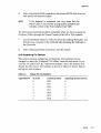
Return and
Repair Policy WARRANTY PERIOD
The following warranty period is from the date of shipment:
CMD Host Adapter
one year
Cable
90 days
Drive
manufacturer's warranty
RETURN FOR CREDIT
The allowable period of return for credit from the date of shipment is as follows
CMD Host Adapter
less than 90 days
Cable
less than 60 days
Drive
not applicable
RETURN FOR REPAIR
CMD Host Adapter
In-Warranty (Less then 1 year)
• CMD offers a 15 working day turnaround repair service at the cost of parts only. Defective
boards will be repaired and returned to the customer within 15 working days from the date
of return to CMD.
• CMD also offers two in-warranty 24 hour expediting services:
24 Hour Turnaround Loaner Service:
Under this policy, CMD will ship a loaner in 24 hours during regular working days to the
customer for a charge of $100.00 per loaner. Upon receiving the loaner, customer must return the defective board to CMD within seven (7) days for repair. CMD will repair the defective board and return the board to the customer. Customer must then return the loaner
in seven (7) days after the receipt of the repaired board. Approval for loaner service is
based on credit verification.
24 Hour Turnaround Swap Service:
In the case that the defective board is within the first six (6) months of the warranty, CMD,
at its own option, offers a 24 hour turnaround swap service. CMD will ship the same
model of the board to customer within 24 hours during working days in exchange for the
defective board. CMD will swap with a new board if board is not functional upon arrival.
For all other cases, swap will occur with either a new or refurbished board for a charge of
$200.00. CMD does not offer swap services for boards that are purchased more than six
months from the date of shipment. Customer is responsible for returning the defective
board to CMD within seven (7) days after receipt of the swapped board.
• The remaining warranty period shall apply to the repaired or swapped board.
Out-of-Warranty (more than 1 year)
• CMD offers a 15 working day turnaround repair seroice at a rate of $300.00 plus parts and
freight for all out-of-warranty host adapter boards. Defective boards will be repaired and returned to customer within 15 working days starting with date of return to CMD.
• CMD also offers an Out-of-Warranty 24 Hour Turnaround Loaner Service:
Under this policy, CMD will ship the same model loaner in the 24 hour time frame of working days to customer for an additional charge of $100.00 plus freight per loaner. The loaner
is for use by the customer during the period that the defective board is being repaired. Customer is responsible for returning the defective board to CMD within seven days after the
receipt of loaner and returning the loaner in seven (7) days once the defective board is repaired and received. The approval of the loaner service is at CMD's option and based upon
customer credit verification.
• CMD will extend warranty for a period of six (6) months on any out of- warranty repaired
board.
Cable
In-Warranty (90 days) - free swap.
Out-of-Warranty (90 days) - not applicable.
Drive
In-Warranty (per manufacturer) - manufacturer charge only.
Out-of-Warranty (per manufacturer) - manufacturer charge plus $100 CMD handling.
RETURN FOR UPGRADE/ UPDATE
CMD Host Adapter
In-Warranty (less than 1 year)
• CMD offers a 15 working day turnaround different function upgrade service for boards that can
be upgraded to a higher function; and a free 15 working day turnaround ECa Field Upgrade
for all its boards. CMD will upgrade the hardware of its board to a higher function for a
charge of the difference of list prices of the original and upgraded functions. CMD will
al~ update its board to its latest firmware release at no charge to the customer. Boards will
be upgraded/updated and returned to the customer within 15 working days from the date
of return to.CMD.
• CMD also offers 24 hour turnaround loaner service as stated in "RETURN FOR REPAIR."
• The remaining warranty period shall apply to the updated board. For upgraded board~,
CMD will extend warranty for a period of six months.
Out-of-Warranty (More than 1 year)
• CMD offers a 15 working day turnaround different function upgrade service for boards that can
be upgraded to a higher function at a charge of the difference of list prices of two functions.
CMD also offers a free 15 working day turnaround ECa Field Upgrade for all its boards.
Boards will be upgraded/updated and returned to customer within 15 working days from
the date of return to CMD.
• CMD also offers 24 hours turnaround Loaner Service as stated in "RETURN FOR REPAIR."
• There will be no warranty extension for same function firmware update. For different function Hardware upgrade, CMD will extend warranty for a period of six (6) months.
Drive-same as in RETURN FOR REP AIR.
SHIPPING CHARGES
The following shipping charges apply to all REPAIR, SWAP, LOANER, and UPGRADE UNITS.
In-Warranty
• Domestic - freight from CMD to customer is to be paid by CMD; freight from customer to
CMD is to be paid by customer.
• International - all fees are to be paid by customer (including custom duty and broker fees).
Out-of Warranty
• Domestic - all fees are to be paid by customer.
• International - all fees are to be paid by customer (including custom duty and broker fees).
GENERAL CONDITIONS
All goods returned to CMD including returns for credit, swap returns, loaner returns, and evaluation returns shall remain in good condition. Any damage or alteration done by the customer will
result in a rejection or additional charge to the customer.
Customer must consult CMD Technical Support for authorization of CMD not functional upon
arrival boards and swap requests. CMD Sales personnel must be consulted for authorization of
returned goods for credit and/ or evaluation.
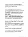
Preface
The CQD-440/443 Rev 1.0 is an entirely new manual. Other revisions will
describe changes to the previous manual in the Preface.
Preface
vii
viii
Preface
Table of Contents
1
Introduction
How to Use this Manual
Conventions
2 Features and Specifications
Features
LED Indicators
Special Features
Multi-Hosting
Partitioning
Tape Monitor Utility
SCSlformat ON-LINE
Hardware Shadowing
Specifications
3
Installation
Determining CSR Address
Hardware Configuration
CSR Address Selection
Disk Auto Boot Selection
18- or 22-Bit Address Selection
Interrupt Level Selection
Block Mode DMA
Adaptive DMA
DMA Dwell Time
Adaptive DMA Dwell Time
Tape Fast Search Option
1·1
1-1
1-2
2-1
2-1
2-3
2-4
. 2-4
2-4
2-4
2-5
2-5
2-6
3·1
3-1
3-3
3-3
3-6
3-6
3-6
3-7
3-7
3-8
3-8
3-9
Table of Contents
ix
Sync/ Async Mode Selection
Tape Monitor Utility and SCSlformat ON-LINE
Single-ended or Differential Mode Selection
Single-ended Active /Passive Termination
Eprom Size
Wait State for Eprom Cycles
Reset Switch
Installation
SCSI Host Adapter ID Selection
SCSI ID for Target Devices
CQD-440 Mounting Slot Selection
SCSI Bus Cabling
SCSI Bus Termination
SCSI Bus Terminator Power
Installation Procedures
4
Setup
On-Board Utility
Accessing the Utility Through the LSI or VAX System
Accessing the Utility Through the RS-232 Port
Changing LUN Offset
Formatting the Drive
Qualifying the Drive
Manually Replacing Bad Sectors
Additional Utilities
Completing Utility Functions
Unit Numbering For Devices
Multi-Hosting Configuration
Partitioning Configuration
Hardware Shadowing Configuration
Configuration Instructions
Detecting Shadowing Errors Using VMS
VMS Configuration
ULTRlX Configuration
CQD-440/TM
5
SCSI Basics
SCSI Glossary
SCSI Commands
x
Table of Contents
3-9
3-10
3-10
3-12
3-13
3-13
3-14
3-14
3-14
3-14
3-15
3-15
3-16
3-16
3-17
4·1
4-1
4-1
4-4
4-6
4-7
4-8
4-8
4-9
4-16
4-17
4-19
4-21
4-24
4-24
4-26
4-27
4-28
4-28
5·1
5-1
5-2
SCSI Status
SCSI Messages
SCSI Single-Ended Signals
Single-Ended Non-Shielded Connector
Single-Ended Shielded Connector
SCSI Differential Signals
Differential Non-Shielded Connector
Differential Shielded Connector
5-3
5-4
5-4
5-4
5-6
5-8
5-8
5-9
Appendices
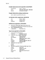
A Supported Devices and Operating Systems
SCSI Devices
Magnetic disk drives supported by CQD-440/TM
Erasable Optical disk drives supported by CQD-44 0 /TM
Erasable Optical disk cartridge manufacturers
CD ROM disk drives supported by CQD-440/TM
WORM drives supported by CQD-440/IM
Tape drives supported by CQD-440 /IM
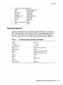
Operating Systems
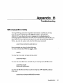
B
Troubleshooting
VMS Analyze/Error Utility
Cables
LED Indicators
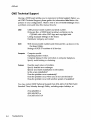
CMD Technical Support
C
Jumper Settings
Pin Assignments
CSR Address Selections
D
VMS SYSGEN Connect Statement
A-1
A-I
A-I
A-2
A-2
A-2
A-2
A-2
A-3
8-1
B-1
B-3
B-3
B-4
C-1
C-l
C-6
D-1
Table of Contents
xi
xii
Table of Contents
List of Figures
2
Features and Specifications
2-1: LED Indica tors
3
Installation
3-1: Example of SYSGEN Utility
3-2: Jumper block locations
3-3: Single-ended Mode Selection
3-4: Differential Mode Selection
3-5: Pin 1 location for single-ended termination
3-6: Eprom Setting
3-7: CQD-440 non-shielded cable connection
3-8: CQD-443 shielded connection
3-9: SCSI ID and Cabling
4
2-3
3-3
3-5
3-11
3-11
3-12
3-13
3-18
3-18
3-19
Setup
4-1: Utility CSR address
4-2: Main Menu
4-3: CQD-440 RS-232 Port
4-4: CQD-443 RS-232 Port
4-5: SCSI Host Adapter Utility
4-6: Utility Sub-menu
4-7: Current configuration, default
4-8: Configuration change
4-9: SCSI host adapter ID change
4-10: Disk and Tape Configuration Change
4-11: Current configuration
4-12: Configuration change
4-13: Partitioning example
4-3
4-4
4-5
4-5
4-6
4-9
4-10
4-11
4-13
4-14
4-21
4-22
4-22
List of Figures
xiii
4-14: Current configuration
4-15: Hardware Shadowing example
4-16: Current configuration
4-23
4-25
4-26
5 SCSI Basics
5-1: SCSI device non-shielded connector
5-2: SCSI device shielded connector
5-4
5-6
Appendices
C Jumper Settings
C-1: Pin Locations for J6 (CQD-440) and J7
C-2: Pin Locations for J5 (CQD-443)
C-1
C-1
D VMS SYSGEN Connect Statement
D-1: SYSGEN Config File
D-2: Unibus Address
xiv
List of Figures
D-2
D-3
List of Tables
2
Features and Specifications
2-1:
2-2:
2-3:
2-4:
2-5:
3
CQD-440 Models
LED Indicators
Special Feature Support List
Controller Specifications
CSR Addesses
Installation
3-1: CQD-440 CSR jumper settings for disk
3-2: CQD-440 CSR jumper settings for tape
3-3: Disk Auto Boot Selection
3-4: Block Mode DMA
3-5: Adaptive DMA
3-6: DMA Dwell Time
3-7: Adaptive DMA
3-8: Tape Fast Search Option
3-9: Sync/ Async Mode Selection
3-10: Tape Moni tor Utility and SCSIformat ON-LINE Options
3-11: Single-ended or Differential Mode Selection
3-12: Single-ended or Differential Mode Selection
3-13: Eprom Size Selection
3-14: Wait State for Eprom Cycles
3-15: Reset or NMI Switch
3-16: Terminator Power Option
4
2-2
2-3
2-4
2-6
2-7
3-4
3-4
3-6
3-7
3-7
3-8
3-8
3-9
3-9
3-10
3-10
3-12
3-13
3-13
3-14
3-17
Setup
4-1: Disk CSR Addresses Plus 2 Configurations
4-2: Tape CSR Addresses Plus 2 Configurations
4-2
4-3
List of Tables
xv
4-3: Default for Unit Numbers
4-4: Host Adapter ID Selection
5
4-17
4-19
SCSI Basics
5-1: SCSI Commands (MSCP)
5-2: SCSI Commands (TMSCP)
5-3: SCSI Status
5-4: SCSI Messages
5-5: Single-Ended Non-Shielded Connector Pin Assignments 02)
5-6: Single-Ended Shielded Connector Pin Assignments 02)
5-7: Differential Non-Shielded Connector Pin Assignments (11)
5-8: Differential Shielded Connector Pin Assignments 01)
5-2
5-3
5-3
5-4
5-5
5-7
5-8
5-9
Appendices
A
Supported Devices and Operating Systems
A-I: Operating Systems Supported by CQD-440/443
C
Jumper Settings
C-l:
C-2:
C-3:
C-4:
C-5:
C-6:
C-7:
C-8:
xvi
A-3
List of Tables
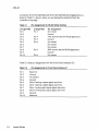
Pin Assignments for RS-232 Utility Interface
Pin Assignments for Front Panel Interface J7
Host Adapter ID Selections
Switch Settings
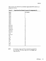
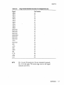
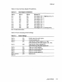
CQD-440 Pin Assignments
CQD-440 Pin Assignments (continued)
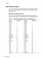
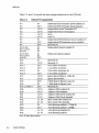
CQD-440/TM CSR Addresses (Disk Only)
CQD-440 /TM CSR Address Selections (Tape Only)
C-2
C-2
C-3
C-3
C-4
C-5
C-6
C-7
1
Introduction
This User's Guide explains the basics of your CQD-440™. It includes
information on setting up and configuring the system and the CQD-440 for
use.
How to Use this Manual
This guide has five chapters and four appendices. Each chapter explains a
different aspect of preparing your CQD-440 for use. You may refer to the
appendices for further configuration and troubleshooting information. The
following descriptions summarize each section.
Chapter 1: Introduction explains the purpose of this guide and details the
conventions used.
Chapter 2: CQD-440 Features describes the CQD-440 and details its features,
special features, and specifications.
Chapter 3: Installation describes hardware configuration and installation
procedures for the CQD-440.
Chapter 4: Setup describes setting up and configuring the CQD-440 and your
system for use; this chapter includes Multi-hosting, Partitioning, Shadowing,
VMS~, and ULTRIX® set up and configurations.
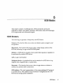
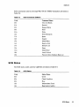
Chapter 5: SCSI Basics lists a glossary on SCSI terms, SCSI status and
command codes for the CQD-440.
Appendix A: Supported Devices and Operating Systems lists the SCSI
devices and operating systems compatible with the CQD-440.
Introduction
1-1
CQD-440
Appendix B: Troubleshooting gives some troubleshooting guidelines for the
CQD-440.
Appendix C: Jumper Settings lists the jumpers settings, pin assignments, and
the CSR addresses for the present revision of the CQD-440.
Appendix D: VMS SYSGEN Connect Statement describes the proper use of
the VMS SYSGEN Connect Statement.
Conventions
The following conventions are used in the CQD-440 User's Guide.
Keycaps-Characters in square brackets represent keys on your keyboard. For
example, "Press [ENTER]" means press the [ENTER] key. When two or more
keys are joined by a plus sign (+), press those keys at the same time.
Commands-Italics text represents a command that can be used on a system,
such show dev duo
NOTE
Sometimes italics will be used for emphasis; at this time
no action is necessary; for example, do not remove
jumper shunt W13.
Entering Text or Commands on Screen-Text or commands that must be
entered on screen will be in italics and bold as show dev du; be sure to enter
the text or command and press [ENTER].
1-2
Introduction
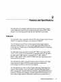
2
Features and Specifications
The CQD-440 is an intelligent high performance quad-wide Q-bus singleended/ differential synchronous/ asynchronous (sync/ async) SCSI-2 Host
Adapter. The following sections describe the CQD-440 in more detail.
Features
The CQD-440 is fully compatible with the DEC Mass Storage Control Protocol
(MSCP) and Tape Mass Storage Control protocol (TMSCP).
The CQD-440 has one SCSI port which supports either single-ended or
differential SCSI channels. You can use the single-ended SCSI channel for
connecting up to 20-feet cable or the differential SCSI channel for connecting
up to 80-feet cable.
The CQD-440 can be used with the LSI-11/23@, PDP-11/23+, Micro-PDP11/53®, 11/73, 11/83, 11/93, MicroV~' II, and MicroVAX III, VAX 4000~
and DECsystem® 5400 systems. It supports RT-11®, TS~, DSM-11@,
ISM-11@, RS~, RSTS®, VMS, UNI:XE, ULTRIX, and other operating systems
which use DU/TU drivers.
The CQD-440 has Adaptive Dwell for Q-bus; active termination for singleended channel to improve SCSI bus noise immunity; a polyswitch
(self-healing) fuses that do not need to be replaced.
The CQD-440 features 18-bit or 22-bit Q~bus addressing, block mode and
adaptive DMA transfer, virtual data buffer, command queuing, dynamic
defect management, standard SCSI bus arbitration, disconnect and reconnect
capability, multiple-host capability, and all required SCSI commands. Up to
seven (either single-ended or differential) synchronous, asynchronous or
Features and Specifications
2-1
CQD-440
mixed SCSI devices can be connected to the CQD-440 with SCSI bus data
transfer rate up to 10-MB/sec in synchronous mode (fast SCSI) and 7-MB/sec
in asynchronous mode.
The CQD-440 supports a variety of Sync/ Async SCSI devices including
magnetic disk, magnetic tape and optical disk drives. Table 2-1 lists the
different models of the CQD-440 and their features.
Table 2-1
CQD-440 Models
CQD-440/TM
CQD-440/TMS
CQD-443
NOTE
supports disk and tape drives Simultaneously
supports disk and tape drives and hardware shadowing
contains the CQD-440 models and a Micro VAX ill and VAX4000
adapter kit. A shielded SCSI cable (with shielded connectors) is
required to connect the CQD-443 to SCSI devices.
Unless otherwise specified, the CQD-440 will represent
all of the variations through this manual and the
CQD-440 /TM will represent the CQD-44 0/TMS variations.
The CQD-440 has an On-Board Utility for you to format and configure the
SCSI devices, scan bad blocks and replace them automatically.
For LSI systems only, the CQD-440 contains a selectable bootstrap option which
can boot up the system on power up or reset. The CQD-440 has an On-Board
Utility for you to boot up the system or exercise the tape drives.
The CQD-440 has an on-board non-volatile RAM (NOVRAM) to store the
Logical Unit Number (LUN) Offset and other important information of the
controller configuration.
The CQD-440 SCSI host adapter provides you with a 10 pin connector 04) for
the On-Board RS-232 Utility. The CQD-443 provides you with a DEC
compatible RJ-11/Modified Module 423 Jack (MMJ) for accessing the
On-Board RS-232 Utility. See Appendix C for pin assignments.
2-2
Features and Specifications
CQD-440
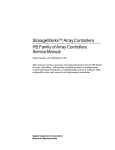
LED Indicators
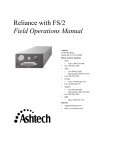
The CQD-440 has three LED modules in the front of the board. The LED modules contain two LED's and are labeled DS1, DS2 and DS3 (see Figure 2-1).
Jl
Red LED
Agure 2-1: LED Indicators
Table 2-2 lists the LED indicators for CQD-440.
Table 2-2
LED Indicators
LED
OS1
Color
Green
Location
first left
053
Red
Green
second left
third left
052
Green
Green
right
left
Green
right
Indication
Power-up OK and activity indicator. Upon power
up, this LED is turned on when the CQO-440
succeeds in the self-diagnostic testing. During
normal controller operation, this LED will blink to
show controller activity.
Error condition occurred
J2 single-ended tenninator power pin is supplied
with power.
}2 Single-ended SCSI channel enabled.
Jl differential terminator power pins is supplied
with power.
Jl Differential SCSI channel enabled.
Features and Specifications
2-3
CQD-440
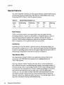
Special Features
The CMD CQD-440 controller provides special features, such as multi-hosting,
partitioning, hardware shadowing, Tape Monitor Utility(TMU), and on-line
formatting (FMT). Table 2-3 lists the special features.
Special Feature Support List
Table 2-3
Model
Multi-hosting
Partitioning
TMU
FMT
/TM
Yes
Yes
/TMS
No
No
Yes
Yes
Yes
Yes
Shadowing
No
Yes
Multi-Hosting
CMD's multi-host solution can support disk, tape, and optical devices
including jukeboxes. It· gives you the ability to completely share an array of
disks and tapes between multiple VAX systems running VAX cluster
software. Multi-hosting configuration instructions are given in Chapter 4.
Refer to Appendix A for supported disk and tape devices.
Partitioning
CQD-440 gives you the ability to partition devices. Partitioning makes one
physical device appear as two or four equal sized logical devices. Partitioning
is used for operating systems that do not support large devices such as RT-l1.
Partitioning configuration instructions are given in Chapter 4.
Tape Monitor Utility
The Tape Monitor UtilityTM (TMU) is an application software that works
exclusively with CMD SCSI host adapters as an optional feature for
VAX/VMS systems.
This Tape Monitor UtilityTM displays the tape drive vendor identification,
drive firmware revision, the remaining tape capacity, percentage/number of
rewrites during writes or percentage/number of ECC retrys during reads (see
manufacturer's documentation for returns whether percentages or numbers),
and current tape operations such as read, write, write file mark, space,
rewind, etc. You can install multiple CQD-440's and tape drives in one site
and observe all tape activity from any VAX terminal locally or across the
network without any additional add-in hardware. You can also open a file to
log all the information during unattended backup.
2-4
Features and Specifications
COD-440
To install the Tape Monitor Utility, follow the instructions given in the
accompanying CMD Tape Monitor Utility User's Manual part number
MAN-DOOTMU-OOO and install jumper shunt as given in Chapter 3, subsection
"Tape Monitor Utility and SCSIformat ON-LINE."
SCSlformat ON-LINE
The SCSIformat ON-LINE (FMT) is an application software that works
exclusively with CMD SCSI host adapters as an optional feature for
VAX/VMS systems. This SCSIformat ON-LINE allows you to format the disk
drives without interfering with the other devices on the SCSI bus. To install
SCSIformat ON-LINE follow the instructions given in the accompanying
SCSIformat ON-LINE User's Manual and install jumper shunt as given in
Chapter 3, subsection "Tape Monitor Utility and SCSIformat ON-LINE."
Hardware Shadowing
The Super Shadow CQD-440/TMS is a hardware variation of the
CQD-440 /TM. Installation and setup of CMD shadowing host adapters are
simplified with the CMD On-Board Utilities. This easy to use menu-driven
utility allows you to quickly configure virtually any combination of disk
shadow sets. See Chapter 4 for Hardware Shadowing Configuration.
The hardware disk shadowing on DEC computers enables simultaneous
writing of data to two shadow set members. This provides an exact real-time
duplicate data set that can be later retrieved by the user if data on primary
disk becomes unaccessible.
The access performance benefits are derived from the ability to read data from
a particular disk in the shadow set that responds faster. By adapting specific
host adapter resident firmware algorithms, CQD-440/TMS provides
incredible performance benefits with disk access time reduced 100% or more
during reads.
The hardware-based shadowing technique also results in far less VMS
overhead and much higher data availability than software solutions.
You can now configure complete SCSI drive failure tolerant subsystems built
around Super Shadow host adapters. When used in conjunction with other
CMD exclusive features like Multi-Host capability, subsystem data
availability can be increased substantially.
Features and Specifications
2-5
CQD-440
Specifications
Table 2-4 lists the controller specifications for the CQD-440.
Table 2·4
Controller Specifications
Emulation
Bus Interface
Addressing
Interrupt Priority
Interrupt Vector
Transfer Mode
DMA Dwell
Command Queuing
Data Buffer Capacity
Bootstrap
Defect Management
Software Supported
Multiple-Hosting
Formatting
Partitiorting
Shadowing
Optional Software
LED Indicators
Peripheral Interface
SCSI Transfer Rate:
SCSI Bus Parity
Devices Supported
System Performance
SCSI Driver /Receiver
SCSI Fuse
SCSI Termination
SCSI Cable Length
Operating Temperature
Relative Hwnidity
Power Requirement
2-6
Features and Specifications
MSCP (DU driver) / TMSCP (TU driver)
Standard MicroVAX or LSI -11 Q-bus
22-bit Addressing
Level 4
Software programmable
Normal or block mode DMA
Adaptive Dwell
Commands with optimized seek
Virtual data buffer (infinite size)
Auto bootstrap or utility bootstrap
Dynamic defect management
All standard DEC operating- systems
Support multiple-hosting for disks, optical drives
and tapes.
On board format and bad block replacement (ISO
standard for optical erasable disk format)
2 or 4 equally divided partitiOns for disk drives
Any two disk drives on the bus can form a
shadow set (for /TMS version only)
Tape Monitor Utility (TMU)
SCSIfonnat ON-LINE (PMT)
Self test, error conditions
Small Computer System Interface (SCSI-2)
10-MB/sec in Synchronous mode (Fast SCSI)
7-MB/sec in Asynchronous mode
Odd parity
Up to 7 SCSI disk and tape devices
(single-ended or differential)
CQD-440/TM default = 4 disks/3 tapes
Support disconnect/reconnect capability and
multiple-host configuration
Single-ended or differential
Self-healing, 1.5 A polyfuse
Single-ended=active termination (removable)
Differential=removable
Single-ended, up to 20-feet (6-meters)
Differential, up to SO-feet (25-meters)
50 C to 50 0 C
10% to 90% , Non-condensing
5V DC, 3.5 A
CQD-440
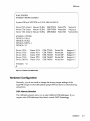
Table 2-5 lists the CSR addresses for the CQD-440. For complete CSR
addresses, see Chapter 3 and Appendix C.
Table 2-5
CSR Addesses
CQD-440/TM (Disk only)
IC P44009A (U93)
772150,760334,760354,760374,760340,760344,
760350, 760360 and up to 30 CSR addresses
CQD-440/TM (Tape only)
IC P44010A (U79)
774500,760404,760444,760504,760544,760410,
760450, 760454 and up to 31 CSR addresses
Features and Specifications
2-7
CQD-440
2-8
Features and Specifications
3
Installation
This chapter instructs you on configuring the CQD-440 and installing it into
the system. Follow the instructions in this chapter in the order presented.
Determining CSR Address
Before you install the CQD-440 SCSI host adapter under the VMS operating
system you must determine the Control and Status Register (CSR) address for
the CQD-440.
For the CQD-440/TM, two CSR addresses are required. The following
proced ure shows one method of determining the new CSR address for the
CQD-440.
WARNING
Do not install the new CQD-440 in the system at this time.
1
Boot the VMS system and log into the system manager account.
2
At the OCL $ prompt, enter Me SYSGEN.
3
At the prompt SYSGEN, enter SHOWICONFIG. The SYSGEN Utility
will display all the device controllers installed in the system and their
corresponding CSR addresses and vectors. Make a note of this list.
4
At the prompt SYSGEN, enter CONFIG. This will give you the DEVICE
prompt
Installation
3-1
CQD·440
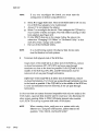
At the prompt DEVICE, enter the following for your CQD-440:
5
enter UDA, X
and TU8l, Y
where
X is the number of installed UDA type controllers plus 1 (for the new
one being added).
Y is the number of installed TUBl type controllers plus 1 (for the new
one being added).
NOTE
6
Enter all devices on the Q-bus, not just the new device
being added at present.
At the prompt DEVICE, enter [CTRL] + Z. The SYSGEN Utility will
display the CSR ~ddresses for all the controllers. Make sure that no other
vectors or CSR addresses have changed; if they have, make the
appropriate changes to the devices.
The VMS mnemonic for MSCP disk controllers are PUA, PUB, PUC, etc.
The VMS mnemonic for TMSCP tape controllers are PTA, PTB, PTC, etc.
For other mnemonics, refer to VMS system manager's guide.
Use the corresponding CSR address to configure the CSR jumper
. settings of the CQD-440 (see IJCSR Address Selection").
7
NOTE
At the prompt SYSGEN, enter
[CTRL] + Z
to exit the SYSGEN Utility.
VMS will automatically program the CQD-440's interrupt
vector register to match the vector assigned by the
system. The vectors of DHV11 or other controllers might
change when the CQD-440 is added to the system; see
manufacturer's documentation to configure vectors and
device CSR addresses if hardware selectable.
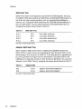
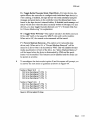
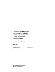
The example in Figure 3-1 explains the SYSGEN Utility procedure for
installing the CQD-440 in VMS system. In this example, the CSR
addresses of PUB and PTB should be used to configure the CSR jumpers
of the CQD-440. In the example, notice the CSR and vector changes for
the DHV11.
3-2
Installation
CQD-440
$MC SYSGEN
SYSGEN> SHOW /CONFIG
System CSR and VECTOR on 2-JUN-19B9 04:10:43.30
Name: PUA Units:1 Nexus:O (UBA)
Name: PTA Units:1 Nexus:O (UBA)
Name: TXA Units:16 Nexus:O (UBA)
CSR:772150 Vector:774
CSR:774500 Vector:260
CSR:760440 Vector:300
Vector2:0
Vector2:0
Vector2:304
SYSGEN> CONFIG
DEVICE> UDA,2
DEVICE> TUB1,2
DEVICE> DHV11,1
DEVICE> /\Z
Device:
Device:
Device:
Device:
Device:
UDA
TUB1
UDA
TUB1
DHV11
Name:PUA
Name: PTA
Name: PUB
Name: PTB
Name:TXA
CSR:
CSR:
CSR:
CSR:
CSR:
772150
774500
760334*
760404*
760500
Vector:l54
Vector:260
Vector:300*
Vector:304 *
Vector:310*
Support:
Support:
Support:
Support:
Support:
Y
Y
Y
Y
Y
SYSGEN> /\Z
$
Rgure 3·1: Example of SYSGEN Utility
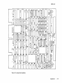
Hardware Configuration
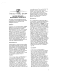
Normally, you do not need to change the factory jumper settings of the
CQD-440 except for the CSR address jumper SW1 as shown in the following
subsections.
CSR Address Selection
The CQD-440 jumpers allow you to select different CSR addresses. If you
require other CSR addresses than listed, consult CMD Technology.
Installation
3·3
CQD-440
The CQD-440 with both the IC P44009A in U93 and the IC P44010A in U79
supports 30 disk and 31 tape CSR addresses. Only eight disk and tape CSR
jumper settings are shown in Tables 3-1 and 3-2. Refer to Appendix C for the
other CSR jumper settings.
WARNING
Table 3-1
Address
1
2
3
4
5
6
7
8
Table 3-2
Address
1
2
3
4
5
6
7
8
Be sure to wear anti-static wrist straps or equivalent to
protect the CQ0-440 from electro-static damage.
CQD-440 CSR jumper settings for disk
LSI-II
17772150
17760334
17760354
17760374
17760340
17760344
17760350
17760360
MicroVAX
20001468
200000DC
200000EC
200000FC
200000EO
200000E4
200000E8
200000FO
SWI-I SWI-2 SWI-3 SWI-4 SWl-S
ON
ON
ON
ON
ON
ON
ON
ON
Installation
ON
ON
ON
ON
OFF
OFF
OFF
OFF
ON
ON
OFF
OFF
ON
ON
OFF
OFF
ON
OFF
ON
OFF
ON
OFF
ON
OFF
CQD-440 CSR jumper settings for tape
LSI-II
17774500
17760404
17760444
17760504
17760544
17760410
17760450
17760454
MicroVAX
20001940
20000104
20000124
20000144
20000164
20000108
20000128
2000012C
SWI-6 SWI-7 SWI-8 SWI-9 SWI-IO
ON
ON
ON
ON
ON
ON
ON
ON
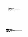
Please refer to Figure 3-2 for jumper locations.
3-4
ON
ON
ON
ON
ON
ON
ON
ON
ON
ON
ON
ON
ON
ON
ON
ON
ON
ON
ON
ON
OFF
OFF
OFF
OFF
ON
ON
OFF
OFF
ON
ON
OFF
OFF
ON
OFF.
ON
OFF
ON
OFF
ON
OFF
CQD-440
Rgure 3·2: Jumper block location.
Installation
3-5
CQD-440
Disk Auto Boot Selection
Disk Auto Boot Selection is used for the LSI-II processors only. The CQD-440
may be set to provide an auto-bootstrap at 773000 or 771000 on power up or
whenever the "boot" switch is pressed. Disk drive 0 will be bootstrapped.
Table 3-3 lists Disk Auto Boot Selections.
Table 3-3
W24
W24
W23
W23
Disk Auto Boot Selection
1-2 IN
. 2-3 IN
IN
OUT
Auto-Bootstrap disabled (F)
Auto-Bootstrap enabled
Auto-Bootstrap address = 773000 (F)
Auto-Bootstrap address = 771000
Note that (F) means factory setting.
If there is an existing bootstrap ROM at 773000, you must set the CQD-440
auto-bootstrap address at 771000. To boot the CQD-440, type 771000G from
ODT instead of the normal 773000G.
18- or 22-Bit Address Selection
The CQD-440 is factory configured to 22-bit addressing which is used in
systems with the MicroVAX, LSI-11/23/53/73/83/93 and Mentec MBO, M90,
M100 processors. 22-bit addressing can cause problems if used with an 18-bit
processor such as the LSI-11/2. In this case, configure the board to 18-bit by
cutting the etch between W32 1-2 (see Figure 3-2 for jumper block locations).
Interrupt Level Selection
Interrupt Level Selection allows you to select the priority of interrupting the
CPU for MSCP devices. The CQD-440 is shipped with interrupt level 4
selected; this is standard interrupt priority for MSCP devices. Interrupt at
levelS can be achieved by cutting the etch between W31 1-2.
3-6
Installation
CQD-440
Block Mode DMA
Block Mode DMA allows the CQD-440 to transfer data in blocks rather than
single word per memory address assertion. In a Block Mode Direct Memory
Access (DMA) transfer, the starting memory address is asserted, followed by
data for that address, and data for consecutive addresses. Because the
assertion of the address for other data words are eliminated, higher data
throughput can be achieved. The CQD-440 is shipped with Block Mode DMA
enabled as shown in Table 3-4.
Table 3-4
Block Mode DMA
1-2 IN
2-3 IN
W22
W22
Block mode DMA enabled (F)
Block mode DMA disabled
Note that (F) means factory setting.
Adaptive DMA
Adaptive DMA allows the CQD-440 to release the Q-bus after a block (eight
words) transfer if other DMA devices assert DMA request. Otherwise, the
CQD-440 will continue the DMA transfer for an additional block then release
the Q-bus. Adaptive DMA is implemented to utilize the Q-bus bandwidth.
The CQD440 is shipped with Adaptive DMA enabled as shown in Table 3:-5.
Table 3-5
W20
W20
Adaptive DMA
1-2 IN
2-3 IN
Adaptive DMA enabled (F)
Adaptive DMA disabled
Note that (F) means factory setting.
Installation
3-7
CQD-44 0
DMA Dwell Time
DMA Dwell Time is the relaxation period between DMA requests. Normally,
if multiple DMA data transfers are performed, consideration must be given to
the Q-bus for other system functions, such as communication multiplexer,
network, etc. During the DMA dwell time, the CQD-440 will not arbitrate for
the use of the Q-bus. You can select the period of the DMA Dwell Time by
changing the jumper shunts listed in Table 3-6.
Table 3-6
W16-1
W16-2
W16-3
W16-4
DMA Dwell Time
OUT
OUT
IN
OUT
O.S-us DMA
1.6-us DMA
3.2-us DMA
6.4-us DMA
dwell time
dwell time
dwell time (F)
dwell time
Note that (F) means factory setting.
Adaptive DMA Dwell Time
When Adaptive DMA Dwell Time is enabled, the CQD-440 monitors the
DMA activity, if other devices are requesting the bus, the Dwell Time will be
determined by W16 as shown in Table 3-6. If no other device is requesting the
bus, the CQD-440 will request the bus immediately. This feature allows the
CQD-440 to be both fast and fair to other devices on the Q-bus. You can select
Adaptive Dwell DMA Time by changing the jumper shunts listed in Table 3-7.
Table 3-7
W21
W21
Adaptive DMA
1-2 IN
2-3 IN
Note that (F) means factory setting.
3-8
Installation
Adaptive Dwell DMA enabled (F)
Adaptive Dwell DMA disabled
CQD-440
Tape Fast Search Option
When set to the Tape Fast Search mode, the CQD-440 will enable high speed
forward and reverse filemark search. VMS may use this mode if you do not
attempt a standalone boot or run other programs that require the controller to
keep track of the number of data records between filemarks. In VMS
standalone boot application, this option needs to be disabled. For the
ISM-II operating system, this jumper shunt has to be installed. CMD
recommends you use this option for ULTRIX and UNIX systems. Table 3-8
lists the jumper settings.
Table 3·8
Tape Fast Search Option
SW2-4
ON
SW2-4
OFF
Enable tape fast search option
Normal operation (F)
Note that (F) means factory setting.
Sync/Async Mode Selection
The CQD-440 comes standard in synchronous (sync) mode. Most SCSI
devices support to sync mode. In sync mode, CQD-440 will automatically
communicate with each SCSI device connected to find out whether the sync
mode is supported by the device.
In async mode, CQD-440 will communicate with the SCSI device
asynchronously even if the SCSI device supports sync mode. Most of the sync
SCSI devices also support async. mode.
You can change the CQD-440 to async mode using the jumpers listed in Table
3-9; these jumpers control the overall sync/ async mode selection and will
override the On-Board Utility sync mode set-up.
Table 3-9
Sync/Async Mode Selection
SW2-6
ON
SW2-6
OFF
SW2-7
ON
SW2-7
OFF
Tape sync mode disabled
Tape sync mode enabled (F)
Disk sync mode disabled
Disk sync mode enabled (F)
Note that (F) means factory setting.
Installation
3-9
CQD-44 0
Tape Monitor Utility and SCSlformat ON-LINE
As explained in Chapter 2, the Tape Monitor Utility will allow you to monitor
tape devices on the SCSI bus; and the SCSIformat ON-LINE will allow you to
format SCSI devices through the CQD-440 and the software provided. To
enable these features you must install the Tape Monitor Utility and
SCSIformat ON-LINE as explained in their respective User's Manuals and
install jumper shunt in SW2-S as shown in Table 3-10. For any operating
system other than VMS, this jumper must not be installed.
WARNING
Table 3-10
Do not insert this jumper shunt if the TMU or FMT application software is not installed. The factory setting of
SW2-5 is in OUT position (disabled).
Tape Monitor Utility and SCSlformat ON·UNE Options
SW2-5
ON
SW2-5
OFF
Tape Monitor Utility enableq. (IT, ITM)
Disk SCSIformat ON-LINE enabled (1M, ITM)
Tape Monitor Utility disabled (F)
Disk SCSIformat ON-LINE disabled (F)
Note that (F) means factory setting.
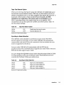
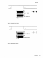
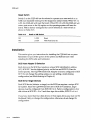
Single-ended or Differential Mode Selection
The CQD-440 SCSI port comes with both single-ended and differential SCSI
drivers and receivers. Jumpers are available for users to select the channel.
When jumper shunts shown in Table 3-11 are installed for single-ended
channel, SCSI drivers and receivers are enabled and DS3 right green LED will
be ON. When a jumper shunts shown in Table 3-11 are installed for
differential channel, differential SCSI drivers and receivers are enabled and
DS2 2nd-Left green LED will be ON. RP1, RP2, and RP3 single-ended
(active or passive) terminators must be installed at all times when using
differenital channel. The factory setting is single-ended channel. Figure 3-3
shows single-ended, and Figure 3-4, differential channel.
Table 3-11
Single-ended or Differential Mode Selection
W8 to W9, Wll to W12, W4, W5
All IN
Single-ended channel enabled (F)
W9 to Wl0, W12 to W13
W4, W5
IN
OUT
Differential channel enabled
Note that (F) means factory setting.
3-10
Installation
CQD-440
J2
J1
we
W9
WI.. W 5 .
W10
o
IN
~mtdmutl!J
IN
'W8 to W9 IN
~
l___~____________~
W13
Figure 3-3: Single-ended Mode
~Iection
J2
J1
Wit
E.3J
OUT
~W9
W5
D
OUT
to W10 IN
r------,
i5
L ___________________________________ .1 ~W12 to W13 IN
W13
Figure 3-4: Differential Mode Selection
Installation
3·11
CQD-440
Single-ended Active/Passive Termination
The CQD-440 has a new feature that allows you to select active or passive
termination. Active termination contains resistor networks and a voltage
regulator. Passive termination contains only resistor networks. Refer to "SCSI
Bus Termination" in this chapter for details on ohms. Table 3-12 details
jumper settings for active/passive termination.
Single-ended or Differential Mode Selection
Table 3·12
W2
. 1-2 IN
W2
2-3 IN
Active Termination enabled (F)
Passive Termination enabled
Note that (F) means factory setting.
Active termination is factory configured, however, to change from active to
passive follow these steps.
1
Remove RP1, RP2, RP3.
2
Place jumper shunt over W2 2-3.
3
Install all passive resistors into RP1, RP2, RP3; final numbers on the
resistors must read 221331. All resistor pin l's must align to the left as
shown in Figure 3-5. [Active resistor numbers end in 111 and pin l's
align to the right.]
Passive Termination
pin 1
111 Screen
IPassive
tjtXXjtjObDo:D RP1
1
Screen
111 ctive
RP2 k I XjOtjbdtX1d
RP3 tx X l( xi i iO¢b
w4D
WSj
Active Termination
pin 1
Figure 3·5: Pin 1 location for alngle-ended termination
3-12
Installation
CQD-440
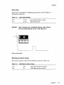
Eprom Size
Eprom size is selectable by installing jumper shunt in W17. Table 3-13
illustrates the selection.
Table 3·13
Eprom Size Selection
W17
W17
WARNING
1-2 IN
2-3 IN
Eprom Size 512-Kbit or 1-Mbit
Eprom 256-Kbit (F)
When removing and reinstalling Eproms, align Eproms
with Ie sockets starting from pin 3. See Figure 3-6.
Pin
Rgure 3-6: Eprom setting
Wait State for Eprom Cycles
Wait state for Eprom cycles can be selected as shown in Table 3-14.
Table 3·14
W18
W18
Walt State for Eprom Cycles
OUT
IN
o Wait State for Eprom Cycles(F)
1 Wait State for Eprom Cycles
Installation
3·13
COD-44a
Reset Switch
Switch 3 on the CQD-440 can be selected to opertate as a reset switch or an
NMI (non-maskable interrupt for the diagnostic utility) switch. When W3 1-2
is IN, the CQD-440 will reset the board. When W3 2-3 is IN, the CQD-440 will
return port errors to the SA register so the operating system will reset the
board. NMI is factory configured but can be selected ~s a reset switch as
shown in Table 3-15 .
Table 3·15
W3
W3
.
Reset or NMI Switch
1-2 IN
2-3 IN
Reset
NMI Port Error (F)
Installation
This section gives you instructions for installing the CQD-440 into a system.
Remember to turn off the power of the system and SCSI devices while
installing the SCSI cable and terminator.
SCSI Host Adapter 10 Selection
Each device on the SCSI bus requires a unique SCSI identification address
(0-7). SCSI ID 7 has the highest priority on the bus and SCSI ID 0 has the
lowest priority. The CQD-440 SCSI Host Adapter is factory configured to SCSI
ID 7. Do not change this setting unless you are setting a multi-hosting
configuration (see Multi-hosting in Chapter 4).
SCSI 10 for Target Devices
Each SCSI device (initiator or target) on the SCSI bus requires a unique SCSI
ID number. Since the CQD-440 has been set to SCSI ID 7 (initiator), target
devices must be configured from SCSI ID 0 to 6. Factory configuration is four
disk drives at SCSI ID = 0 to 3 and three tape drives disks, SCSI ID = 4 to 6.
If you have more than four disks drives or three tapes drives you must use the
On-Board Utility to change the configuration; otherwise, do not change the
configuration.
3-14
Installation
CQO-440
CQD-440 Mounting Slot Selection
The CQD-440 can be installed in any slot of the standard MicroVAX or LSI-II
Q-Bus backplane as long as the Q-Bus interrupt acknowledge/DMA grant
daisy chain is not broken.
SCSI Bus Cabling
Single-ended-The CQD-440 provides a 50-pin connector 02) to interface with
external single-enged SCSI devices.
• When the CQD-440 and the SCSI devices are installed in the same
cabinet which meets EMI/RFI shielding requirements, a 25-signal
twisted-pair cable must be used for connecting the CQD-440 (2) and
the SCSI devices.
• When the CQD-440 and the SCSI devices are installed in separated
cabinets, the shielded SCSI cable should be used to meet FCC
requirements.
• A minimum conductor size of 28-AWG must be used to minimize
noise effects and ensure proper distribution of optional terminator
power.
• The maximum cable length is 6.0-meters or 20-feet in single-ended
channel.
Differential-The CQD-440 also provides a 50-pin connector (1) to interface
with external differential SCSI devices.
• When the CQD-440 and the external SCSI devices are installed in the
same cabinet which meets EMI/RFI shielding requirements, a
25-signal twisted-pair cable must be used for connecting the CQD-440
(1) and the external SCSI devices.
• When the CQD-440 and the external SCSI devices are installed in
separated cabinets, the shielded SCSI cable should be used to meet
FCC requirements. A 25-signal twisted-pair cable must be used to
eliminate the crosstalk between adjacent signals causing spurious
pulses on differential signals which will occur even at slow data
transfer rates and short cable distances. Each pair should be
connected to the same signal, one wire to the positive and the other
wire to the negative signal.
• Cables should consist of conductors of 26-AWG or 28-AWG.
• The maximum cable length is 25-meters or 80-feet in differential
channel.
Installation
3-15
CQD-440
SCSI Bus Termination
The CQD440 can be installed in any position of the SCSI cable. If the
CQD-440 is installed in either end of SCSI cable, on-board terminators should
remain on board. If the CQD-440 is in the middle of the SCSI bus, on-board
terminators should be removed.
Single-ended Active-The CQD-440 uses active removable terminators for
single-ended SCSI. Active termination provides greater noise immunity and
more closely matches the cable impedance. The part number for the sips are
xxxIII (9 by 110-ohms). They are located in the RP1, RP2, and RP3. See
Figure 3-5 for details.
Single-ended Passive-If passive termination is desired, the SCSI bus signals
should be terminated with 220-ohms to +5-volts and 330-ohms to ground at
each end of the cable. The CQD-440 provides on-board removable
terminators, for locations RP1, RP2, and RP3. The sips extension numbers
must end in 221331. See "Single-ended Active/Passive Termination."
Differential-Every differential signal pair should be terminated with
330-ohms resistor between the negative signal and +5-volts, 330-ohms
between the positive signal and ground, and 150-ohms between the positive
and the negative signal at each end of the SCSI cable. The ~QD-440 provides
on-board removable terminators (U1 and U2) which are next to the
connector J1. RPl, RP2, and RP3 single-ended (active or passive) terminators
must be installed at all times when using differenital channel.
SCSI Bus Terminator Power
Any SCSI terminator (on-drive or external) needs to be powered by at least
one SCSI device, otherwise the SCSI signals will be pulled down. Typically an
initiator (SCSI host adapter) provides the power to the on-board terminator,
external SCSI terminator and on-drive terminator when the drive is powered
off. Anytime an external SCSI terminator (instead of the on-drive SCSI
terminator) is used, the SCSI terminator power option of the CQD-440 has to
be enabled, i.e. install jumper shunt at WI or W6.
A minimum conductor size of 28-AWG shall be employed to minimize noise
effects and ensure proper distribution of optional terminator power. The
CQD-440 supplies terminator power to the TERMPWR pin 02, pin 26; J1, pin
25 and 26) and the CDQ-443 02, pin 38; J1, pin 13 and 38), through a fuse, a
diode and jumper block WI for differential and W6 for single-ended (see
Table 3-15).
3-16
Installation
CQD-44 0
Table 3·16
Wl
Wl
W6
W6
Terminator Power Option
IN
OUT
IN
OUT
Differential SCSI terminator power enabled (F)
Differential SCSI terminator power disabled
Single-ended SCSI terminator power enabled (F)
Single-ended SCSI te~tor power disabled
Note that (F) means factory setting.
Installation Procedures
1
Determine the CSR address for the CQD-440 as explained in
"Determining CSR Address."
WARNING
Be sure to wear anti-static wrist straps or equivalent to
protect the CQD-440 from electro-static damage.
2
Configure the hardware as explained in "Hardware Configuration."
3
Set the CQD-440 and Device SCSI ID's as explained in "SCSI Host
Adapter ID Selection" and "SCSI Device ID Selection."
4
Choose a proper slot to place the CQD-440; and install it into that slot
(see "CQD-440 Mounting Slot Selection").
Installation
3-17
CQD-440
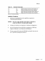
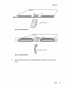
5
Connect SCSI cable to Jl for differential or J2 for single-ended of the
CQD-440 using cable specifications given in "SCSI Bus Cabling." For the
CQD-440, connector will be non-shielded, see Figure 3-7.
WARNING
In order to prevent accidental grounding or misconnection of terminator power, make sure that the ·pin 1 mark of
SCSI cable matches with the pin 1 mark of SCSI device's
connector before turning on the power.
.-c ..• :::.::: :.:.::: ••••.• >.::
>::::»)<:):):::::#-_
_ _ _ Internol
Coble
»
Red stripe designates
pin 1
Rgure 3·7: CQD-440 non-shielded cable connection
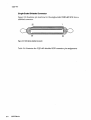
For the CQD-443, the connector will be shielded, see Figure 3-8.
CQD-443
J2
Slngle~nded
Jl Differential
'flmTIES~
Rgure 3-8: CQD-443 shielded connection
3-18
Installation
External Cable
CQD-440
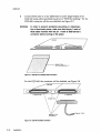
6
Continue SCSI cabling to connect up to seven SCSI devices to the
CQD-440. See the example in Figure 3-9.
SCSI
device
Host
OUAO
SCSI
device
DUA1
SCSI
device
DUA2
SCSI
device
SCSI
device
SCSI
device
OUA3
OUA4
OUAS
J1 or J2 10=7 T
SCSI Bus Cable
T shows termination of
SCSI bus
Figure 3-9: SCSI 10 and Cabling
7
Terminate the SCSI bus at each physical end; see "SCSI Bus Termination."
If TERMPWR is needed for the bus, place jumper shunt on WI or W6 as
explained in "SCSI Bus Terminator Power" (see the example in
Figure 3-8).
8
Power up the system and execute On-Board Utility to scan for the SCSI
devices and assure that all devices are seen and functioning properly
(see Chapter 4 for On-Board Utility).
9
Boot the system and test with the operating system.
Installation
3-19
CQD-440
3-20
Installation
4
Setup
This chapter will assist you in setting up the CQD-440 and your system
for use.
On-Board Utility
The CQD-440 SCSI host adapter comes with a general purpose On-Board
Utility for all systems. The On-Board Utility can test the system slot, SCSI
cable, and SCSI devices connected to the CQD-440. Accessing the Utility can
be done through LSI or VAX system or the RS-232 Port. Be sure to
complete utility functions, explained at the end of this chapter.
Accessing the Utility Through the LSI or VAX System
The On-Board Utility Program can be accessed by means ot an ODT
command for LSI and VAX systems. One example is shown with the SCSI
host adapter set to the first disk CSR address. Because the formats and
features of the On-Board Utilities for LSI-II systems and MicroVAX systems
are similar (except different start up procedures), the MicroVAX utility will be
described.
Instructions for using the Disk Utility with LSI-11 Systems are listed below:
1
Halt the processor.
2
Hit the Boot Switch.
3
Enter the CSR address plus 2 (in Octal), a slash, and 123456. For
example, for CSR address 17772150 enter: 17772152/005400123456. CSR
addresses can be found in Chapter 3 or Appendix C.
Setup
4-1
CQD-44 0
4
Enter CSR address plus 2 (in Octal), a slash, and 100 to load the utility
to the system memory. For example, for CSR address 17772150 enter:
177721521001000 100.
5
Enter 5000G. The Utility program will begin executing.
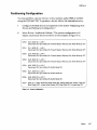
Instructions for using this utility with VAX Systems are listed below:
1
Halt the CPU.
2
At the prompt »> enter U to unlock the CPU.
3
At the prompt »> enter I to initialize the CPU.
4
At the prompt »> enter DIPIW 20001F40 20 to enable Q-bus memory
access.
5
At the prompt »> enter DIL 20088008 80000002 to set up Q-bus map.
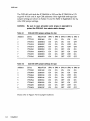
6
At the prompt »> enter DIW YYYYYYYY A72E to deposit to the base
CSR address plus 2 (in Hex). CSR addresses can be found in Chapter 3
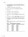
or Appendix C.
Where
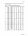
yyyyyyyy-the CSR address plus 2 (in Hex). See Table 4-1 for disk and
Table 4-2 for tape.
Table 4-1
Disk CSR Addresses Plus 2 Configurations
CSR Reference
CSR Addresses
CSR Addresses Plus 2: YYYYYYYY
772150
760334
760354
760374
760340
760344
760350
760360
20001468
200000DC
200000EC
200000FC
200000EO
200000E4
200000E8
200000FO
2000146A
200000DE
200000EE
200000FE
200000E2
200000E6
200000EA
200000F2
CQD-44 0
Table 4-2
Tape CSR Addresses Plus 2 Configurations
CSR Reference
CSR Addresses
CSR Addresses Plus 2: YYYYYYYY
774500
760404
760444
760504
760544
760410
760450
760454
20001940
20000104
20000124
20000144
20000164
20000108
20000128
2000012C
20001942
20000106
20000126
20000146
20000166
2000010A
2000012A
2000012£
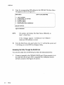
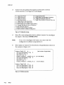
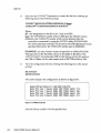
7
At the prompt »> enter D '" 100 to load the utility to system memory.
This command deposits 100 to current address.
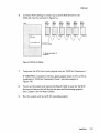
8
At the prompt »> enter S 400 to start the utility. The utility will display
as shown in Figure 4-1:
SCSI UTILITY PROGRAM
DISK
1 = 772150
2 = 760334
3 = 760354
4 = 760374
5 = 760340
6 = 760344
7 = 760350
8 = 760360
TAPE
A = 774500
B = 760404
C =760444
0=760504
E = 760544
F = 760410
G = 760450
H = 760454
SELECT CSR ADDRESS
Figure 4·1: Utility CSR address
Setup
4·3
CQO-440
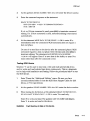
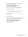
9
Enter the corresponding CSR address for the CQD-440. The Main Menu
will appear as shown in Figure 4-2.
MAIN MENU
1
2
3
4
7
CSR=772150 (20001468)
= HALT SYSTEM
=CONFIGURE LUN OFFSET
= FORMAT DRIVE
= QUALIFY DRIVE
=ADDITIONAL SCSI COMMANDS
SELECT OPTION:
Figure 4-2: Main Menu
LSI systems will display this Main Menu differently as
item 1 = Boot Drive.
NOTE
If the message appears "CONTROLLER NOT PRESENT,"
make sure CSR address is correct.
10
From the Main Menu only select option 1 or 7. 1 will halt the system and
7 will bring you to the SCSI Host Adapter Utility.
(
Accessing the Utility Through the RS-232 Port
To access the utility from the RS-232 port, follow the instructions below.
1
4-4
Setup
Connect a terminal to the CQD-440's RS-232 port (10 pin connector) or to
the CQD-443's RS-232 port (DEC compatible RJ-11/Modified Module
423 Jack connector). See Figures 4-3 and 4-4.
CQD-440
CQD-440
J6
Pin 1
Jl
RS-232 Port
RS-232 Cable Pin 1
To Terminal
Agure 4-3: CQD-440 RS-232 Port
Agure 4-4: CQD-443 RS-232 Port
2
Set the terminal baud rate to 9600 (8-bit data, l-stop bit, no parity) jump
scroll.
Setup
4-5
CQD-440
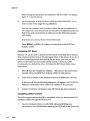
3
Halt the system's CPU, reset the system, and hit carriage return on the
terminal. The SCSI Host Adapter Utility will display as shown in
Figure 4-5.
SCSI HOST ADAPTER UTILITY (REV. YYYxZZ)
[DISK]
[TAPE]
1 = LOGICAL UNIT NUMBER OFFSET
6 = LOGICAL UNIT NUMBER OFFSET
2 =FORMAT DRIVE
7 =ADDITIONAL UTILITIES
3 = QUALIFY DRIVE
4 = MANUALLY REPLACE BAD BLOCKS
5 = ADDITIONAL UTILITIES
SELECT OPTION ?
Figure 4·5: SCSI Host Adapter Utility
Once the SCSI Host Adapter Utility shows up, you can key in the
number to select the desired option. Press [CTRL] + C at any time to
return to the main menu.
4
NOTE
Refer the next subsections for configurations. When completed,
unplug the terminal, reset the system, and boot. DO NOT use the
On-Board Utility while the system is running.
The following sections will illustrate the On-Board Utility from the RS-232 Port. There may be some variation
in the Main Menu and the SCSI Host Adapter Utility
Menu. If you are accessing from the Main Menu, simply
chose the correct number for each option.
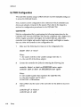
Changing LUN Offset
When a system has a HSC or in a VAX cluster it will be necessary to
change the LUN (Logical Unit Number) offset. Each MSCP drive requires a
different Unit Number so that the unit numbers are not duplicated. If there
are no other MSCP controllers in the system, the LUN offset can be O.
If there exists another MSCP controller with four drives (0 to 3) in a VAX
cluster configuration, then the LUN offset should be four or above. In the case
that LUN offset is equal to 10, SCSI ID will be DUBIO and SCSI ID I will be
DUBIL The drives will show up as such DUAO, DUAl, DUA2, DUA3,
DUBIO, DUBll (see section, "SCSI 10 for Target Drives" in Chapter 3 for
explanation).
°
4-6
Setup
CQD-440
Follow these procedures to configure LUN offset.
1
Select option 1 from the SCSI Host Adapter Utility for disk drives; 6 for
tape drives.
2
Enter the new value for LUN offset at the statement:
LUN OFFSET IS 0,
ENTER NEW V ALOE:
3
At the statement: SAVE NEW VALUE (Y or N)? enter Y.
4
The monitor will display
FORMAT COMPLETE when
finished executing.
Formatting the Drive
This section details formatting a drive. The CQD-440 issues Format Unit
Command to the selected SCSI disk drive and requests it to map out the
defects on the Manufacture Defect List (MDL). Remember formatting a drive
will rewrite all the sectors of that drive.
CMD recommends that you format all new drives. To format a drive, follow
the steps below:
1
Select option 2 from the SCSI Host Adapter Utility.
2
Enter the device number from 0 to 6 in the statement:
DEVICE NUMBER?
<0 TO 6> DEV X.
if you want to
3
Answer Y to the question
continue.
4
At the statement: WARNING DATA WILL BE DESTROYED, ARE YOU SURE?
enter Y if you want to continue.
5
The monitor displays WAIT while the drive is executing the format
process.
6
The monitor will display
FORMAT DRIVE X, ARE YOU SURE?
COMPLETE
when finished executing.
Setup
4-7
CQD-440
Qualifying the Drive
After formatting the device, CMD recommends you qualify devices by
running this procedure at lease once without errors detected. The qualify
program writes different patterns to the drive and then verifies the data. If
there are any bad sectors, the sectors will automatically be replaced and the
statement XX XXXXXXXX BAD BLOCK REPLACED will appear. Follow the
instructions below for qualifying a drive.
1
Select option 3 from the SCSI Host Adapter Utility.
2
Enter the device number at the statement: DEVICE NUMBER? DEV <0 TO 6>
DEVX.
3
At the statement, READY TO TEST DEVICE X, ARE YOU SURE enter Y if you
want to continue.
4
At the statement: ototot WILL DESTROY DATA ON THIS DEVICE, ARE YOU SURE?
enter Y if you want to continue.
5
The monitor will display QUALIFY STARTED <SEQUENTIAL WRITE & READ>!
<HIT <Break> TO ABORT>.
6
The monitor will display TESTING LOOP COUNT & BLOCK NUMBER:
7
Press [BREAK] to exit back to the SCSI Host Adapter Utility after you are
satisfied with the qualifying process.
Manually Replacing Bad Sectors
This option allows you to replace bad sectors manually. The controller
supports dynamic defect management which replaces defective sectors on-line
so there is no need to manually replace bad sectors. However, if you wish to
replace bad sectors manually follow these instructions; remember that any
data in the sector will be lost:
1
Select option 4 from the SCSI Host Adapter Utility.
2
Enter the device number at the statement: DEVICE NUMBER? DEV <0 TO 6>
DEVX:
4-8
Setup
CQD-440
3
Enter the logical block number in HEX at the statement:
READY TO TEST DEVICE X,
ENTER THE BAD BLOCK NUMBER <HEX> :
4
The monitor will display
executing.
xxxxx
--BAD BLOCK REPLACED-- when
finished
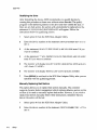
Additional Utilities
To access additional utilities for disk drives, select option 5 from the main
menu. To access additional utilities for tape drives, select option 7 from the
main menu. The additional utilities menu will display as shown in Figure 4-6.
ADDITIONAL UTILITIES
(REV. YYYXZZ)
SN
= 1278
D = DISPLAY SCSI DEVICE AND SET UP CONFIGURATION
S = SEND SCSI COMMAND TO THE DEVICE
T = TEST SCSI DEVICE
R = FORMAT RCT BLOCK
SELECT OPTION?
Figure 4-6: Utility Sub-menu
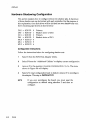
Displaying SCSI Device and Setting Up Configuration
Selection 'D' can be used to change the controller default configurations such
as those listed below:
•
•
•
•
•
•
•
•
•
•
•
•
reset to default
number of disk and tape devices supported
SCSI reset enable / disable
SCSI disconnect enable / disable
sync/ async mode selection
tape buffer mode enable/disable
prevent medium removal enable/ disable
disk write with verify enable / disable
remote density mode enable/disable
default tape enable/disable
reconfigure device
autoboot start from floppy enable/disable
Setup
4-9
CQO-440
•
•
•
write protect from controller jumper setting
truncate disk size for volume shadowing
eject removable disk cartridge after dism"ount
This utility can also scan/display the SCSI devices attached to the CQD-440.
The CQD-440/TM will be shown as an example in the following display. To
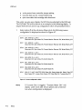
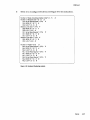
display SCSI devices and set up configuration follow the procedures below.
1
Select option D at the sub-menu (Figure 4-6), the following current
configuration is displayed as shown in Figure 4-7.
DEVO
DUO, SCSI 10 0, LUN 0
Disconnect ON, Sync Mode ON, Prevent Medium Removal ON, Write WNerify OFF
DEV1
DU1, SCSI ID 1, LUN 0
Disconnect ON, Sync Mode ON, Prevent Medium Removal ON, Write WNerify OFF
DEV2
DU2, SCSI ID 2, LUN 0
Disconnect ON, Sync Mode ON, Prevent Medium Removal ON, Write WNerify OFF
DEV3
DU3, SCSI ID 3, LUN a
Disconnect ON, Sync Mode ON, Prevent Medium Removal ON, Write WNerify OFF
DEV4
MUO, SCSI ID 4, LUN 0
Disconnect ON, Sync Mode ON, Buffer Mode ON
DEV5
MU1, SCSI ID 5, LUN 0
Disconnect ON, Sync Mode ON, Buffer Mode ON
DEV6
MU2, SCSI ID 6, LUN 0
Disconnect ON, Sync Mode ON, Buffer Mode ON
DEV7
SCSI ID 7, HOST ADAPTER SCSI Reset ON, Density Mode ON, Default Tape OFF
Boot Floppy OFF, Jumper Write Protect OFF, Eject Disk ON, Truncate Size OFF
Rgure 4-7: Current configuration, default
NOTE
4-10
Setup
If Truncate Size is toggled, "Truncate Mode ON" will
display under each disk device options and at the bottom when configuration is displayed.
CQD-440
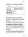
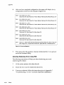
2
To change the configuration, enter Y at the statement: CHANGE
CONFIGURATION? (y IN) The menu shown in Figure 4-8 will display.
See subsection, "Unit Numbering" before trying to reconfigure dey ices.
NOTE
R = Toggle SCSI Reset
M = Toggle Density Mode
D = Toggle Disconnect
B = Toggle BufferlTruncate Mode (Tape/Disk)
S = Toggle Sync/Async
W = Toggle Write WNerity (Disk only)
C = Reconfigure Device
P = Toggle Prevent Medium Removal (Disk only)
U = Toggle Default Tape (Tape Only)
A = Autoboot Start From Floppy Drive
N = Write Protect from Controller Jumper Setting
V Truncate Disk Size for Volume Shadowing
E Eject Disk after Dismount
T = Reset All Device Modes to Default
Z = Reset Controller to Default Configurtation
=
=
Agure 4·8: Configuration change
The following list is an explanation of the selections in Figure 4-8.
R =Toggle SCSI reset-Choosing this option will toggle the controller's
ability to issue SCSI resets. This should be turned off when multi-hosting
is desired.
D =Toggle Disconnect-This option allows you to configure on a
device basis the ability to disconnect or not. If enabled the controller will
indicate its ability to disconnect during the SCSI identify message.
S = Toggle SyndAsync-This option allows you to configure each
device for synchronous or asynchronous operations. If synchronous is
selected, the controller will attempt a synchronous message exchange
with the device. If the device accepts the message exchange, they will
transfer data synchronously, otherwise they will transfer asynchronously.
C = Reconfigure Device-This option allows you to reconfigure the device at any time.
U = Toggle Default Tape-This option allows you to force the presence
of a tape unit to the operating system even if one does not exist. This is
needed for some operating systems when the controller is connected to
Setup
4·11
CQD-44 0
devices with a long self test procedure after power-up. If it is disabled,
only units connected to the controller are seen by the operating system.
A = Autoboot Start From Floppy Drive-This option allows you to set
the system to boot directly from the first floppy drive; if no floppy drive
is present, the system will begin to boot from the first device.
N = Write Protect from Controller Jumper Setting-This option may be
used when jumper setting for write protect is IN to enable further write
protection to the disk. If the jumper is OUT, write protect will not be
enabled.
v = Truncate Disk Size for Volume Shadowing-This option allows
the size of the disk to be truncated to multiples of 126 blocks to allow
VMS volume shadowing copy process to reach higher performance. The
message "** WARNING ** Truncate Size ON/OFF will be toggled, Are
you sure?" will display before truncate switch can be toggled. If this
feature is used on a disk that contains valid data, the data must be
removed and later restored after turning this feature ON.
E = Ej ect Disk after Dismount-This option allows you to specify
whether the removable disk cartridges will eject from the drive after'
dismount.
T =Reset all Device Modes to Default-These modes are--disconnect,
synchronous, Prevent Medium Removal, Write with Verify, and Buffer
modes.
Z = Reset Controller to Default Configuration-This option allows the
you to set the controller to its factory default configuration. This will set
the CQD-440 /TM to support four disk drives, three tape drives;
disconnect, SCSI reset, synchronous communication, buffer mode,
prevent medium removal and density selection enabled; write with
verify and default tape disabled. Use this feature ALWAYS before you
reconfigure the board.
M =Toggle Density Mode-This option allows you to configure the
controller for remote density selection. If enabled, remote density
selection may take place. If enabled, the controller reports itself as a
'TUBI.' If disabled, it reports itself as a 'TKSO.'
4-12
Setup
CQD-440
B = Toggle BufferlTruncate Mode (Tape/Disk)-For tape devices, this
option allows the controller to configure each individual tape device for
write caching. If enabled, the tape device will send command complete
message and good status to the controller once the data as been transferred to the tape device's internal buffers. If disabled, such message and
status will be sent when the data is actually written to the tape. For disk
devices, you may toggle truncate disk size, see "V = Truncate Disk Size
for Volume Shadowing" for explanation.
W = Toggle Write W/Verify-This option will allow the SCSI command
Write with Verify to be issued for MSCP write with verify modifier.
When set to OFF, the normal write command will be issued.
P =Prevent Medium Removal-This option is for removable disk
drives only. When set to ON, a "Prevent Medium Removal" will be
issued to a drive when it is mounted by VMS. This will disable the eject
media push-button in front of the drive. An "Allow Medium Removal"
will be issued when the drive is dismounted by VMS and the pushbutton will be enabled. This features can be disabled and the media can
be ejected at anytime.
3
To reconfigure the device select option C and the screen will prompt you
to answer the next series of questions as shown in Figure 4-9.
Number of Disks? (0-7)
4
DUO to be Reconfigured ?
DU 1 to be Reconfigured ?
DU2 to be Reconfigured ?
DU3 to be Reconfigured ?
(YIN)
(YIN)
(YIN)
(YIN)
N
N
N
N
3
Number of Tapes? (0-3)
MUO to be Reconfigured? (YIN)
MU1 to be Reconfigured? (YIN)
MU2 to be Reconfigured? (YIN)
N
N
N
Rgure 4-9: SCSI host adapter 10 change
Setup
4-13
CQD-440
Enter the number of disk and/or tapes. Default configuration is four
disks, and three tapes; it is not necessary to configure if running less
than four disks and three tapes.
4
NOTE
If zero is selected for the number of disks or tapes disable the corresponding CSR address as shown in Tables
3-1 to 3-4. Do not use 0 disk andlor 0 tape configuration in the above setup.
Answer Y or N to reconfigure each of the disks or tapes. If you answer
Y, the screen will prompt you with these questions:
(DUX SCSI ID? <0-7>
J
C_D_UX
_____L_U_N_?_<_O-_3_>____________________________________________________________________
Rgure 4-10: Disk and Tape Configuration Change
NOTE
5
This LUN is SCSI LUN; it is normally O. This is used
only for devices that support multiple LUNs.
When you have completed these instructions the display will show your
current configuration and prompt you again with the question CHANGE
CONFIGURA nON? (Y IN). Enter N; this will cause the CQD-440 to scan the
SCSI bus.
The utility will display your current configuration with manufacturer's
name, model number, and firmware revisions for each device. Record
this information for future use.
Sending SCSI Commands To The Device
Selection '5' can be used to send SCSI commands to the selected disk/ tape
drives directly.
This option is used to send a 6-, 10-, or 12-byte command to a SCSI device.
Follow these procedures to send SCSI cqmmands to the device:
1
4-14
Setup
Enter S from the Additional Utilities" Menu. (Be sure you have
correctly selected either 5 from the SCSI Host Adapter Utility for disk
drives, or 7 for tape drives.)
II
CQD-440
2
At the question
3
Enter the command sequence at the statement:
DEVICE NUMBER? DEV <0-6> DEV
enter the device number.
READY TO TEST DEVICE X
EDIT CDB <HEX> ...... <ESC> TO TERMINATE EDITING .......
BYTE 0000= 00
If a 6- or lO-byte command is used, press
to terminate command
editing. If a l2-byte command is used, command editi~g is terminated
automaticall y.
4
[ESC]
At the statement WRITE DATA TO THE DEVICE? <Y OR N> enter N to
immediately send the command if SCSI command does not require a
data out phase.
Or enter Y to send data to the device after the command phase if SCSI
command requires a data out phase. Enter the data and enter [ESC] to
terminate editing. The statement SAVE EDITED DATA IN BUFFER?
<Y OR N> will appear. Enter Y to save data in the buffer; or enter N to
erase edited data after the command is sent.
Testing SCSI Device
Selection 'T' can be used to read only, write and read selected disk drive,
and/or write and read selected tape drive continuously. This is a diagnostic
tool to help with installation and testing. Follow the procedures below to test
the SCSI device.
1
Enter T from the Additional Utilities" menu. (Be sure you have
correctly selected either 5 from the SCSI Host Adapter Utility for disk
drives, or 7 for tape drives.)
2
At the question DEVICE NUMBER? DEV <0-6> DEV enter the device number.
3
When testing for disk devices, at the statement READY TO TEST DEVICE X,
00 YOU WANT TO READ ONLY? <Y OR N> enter Y to read only.
1/
Enter N to write and read. The question ARE YOU SURE? will display.
Enter Y to write and read to the device.
WARNING
Nwill destroy all data on the device.
Setup
4-15
CQD-440
When testing for tape devices, the statement ARE YOU SURE? will display.
Enter Y to test the device.
4
At the statement, IS THIS FOR DUAL HOSTS QUALIFICATION TEST? <Y IN>,
enter Y. Enter N for single host qualification.
The test will continue until you abort. Allow the test to continue for a
few minutes for new devices and ten minutes for suspected bad devices.
Bad blocks will automatically be replaced and the following message
will display.BAD BLOCK AT LOGICAL BLOCK XXXXXX REPLACED.
Press [BREAK] or [CTRl] + C to abort and exit back to the SCSI Host
Adapter Utility.
Formatting ReT Block
Selection 'R' can be used to format the RCT blocks of the disk drive selected.
This command writes zeros in the last logical block of the device. If you try to
skip the formatting process and directly use the drive, you must use this
option to eliminate "unrecoverable bad RCT block." However, CMD
recommends you format the drive. To format the RCT block follow these
instructions:
1
Select R from the Additional Utilities." (Be sure you have previously
selected 5 from the SCSI Host Adapter Utility for disk drives.)
2
Enter device number at the statement: DEVICE NUMBER? DEV <~> DEV.
II
If device is off-line the following statement will appear, DEVICE OFFLINE,
RESELECT OR PROCEED? (RIP). Enter R to reselect or P to proceed.
3
FORMAT COMPLETE will display when RCT block has been formatted.
Completing Utility Functions
The following proced ures should be completed when you have accessed the
On-Board Utility through the RS-232 port.
1
4-16
Setup
Use the On-Board Utility to verify SCSI cable and SCSI devices
connected to the CQD-440 after installing the CQD-440 in the Q-bus slot.
CQD-440
2
After verifying the SCSI connections, disconnect RS-232 cable from the
back panel, and reset the system.
If the terminal is connected, this may cause the OnBoard Utility to be invoked during system operation and
will take control of the Host Adapter from VMS.
NOTE
The following procedures should be completed when you have accessed the
On-Board Utility t!'rr0ugh the Virtual Console of the LSI or VAX systems.
1
Use the On-Board Utility to verify the Q-bus slot seating, SCSI cable, and
SCSI devices connected to the CQD440 after installing the CQD-440 in
the Q-bus slot.
2
After verifying the SCSI connections, reset the system.
Unit Numbering For Devices
This section explains configuring unit numbers. Unit numbers may be
changed by using the "Configure LUN Offset" from the main menu. If you
used the 'D' option from the" Additional Utilities" menu, the terminal will
display the MU and/or DU numbers as shown in Table 4-3, factory default
settings for unit numbers.
Table 4-3
CQD-440fTM
Default for Unit Numbers
SCSI 10
On-Board Utility
Operating System Unit N~.
0
DUO
DUl
DU2
DU3
0
MUO
MUl
MU2
0
1
2
3
4
5
6
1
2
3
1
2
Setup
4-17
CQO-440
An example below is given for each type of controller to show how the unit
numbers can be determined. Refer to Figure 4-7 if necessary.
CQD-4401TM-Default is four disk drives and three tape as shown in Table
4-3. If you have more than four disk drives or three tape drives, follow these
guidelines-disk drives must start at SCSI ID 0 and tape drives must start
after the last disk drive's SCSI ID number and reconfigure the CQD-44 0/TM
(see subsection, "Displaying SCSI Devices and Setting Up Configuration").
Note the example .below:
SCSI
SCSI
SCSI
SCSI
SCSI
ID 0 disk
ID 1 disk
ID 2 disk
ID 3 disk
ID 4 disk
SCSI ID 5 tape
SCSI ID 6 tape
SCSI ID 7 is initiator (CQD-440/TM)
The MU and DU numbers are the unit numbers mapped back to the operating
system. If the CQD-440 /TM is configured following these guidelines, you can
apply this formula to determine the unit number mapped back to the
operating system:
+
=
4-18
Setup
SCSI ID of the disk drive
the LUN offset for disk
uni t number for disk
+
=
SCSI ID of tape drive
number of disk drives
LUN offset for tapes
unit number for tape
CQO-440
Multi-Hosting Configuration
The following is a list of software requirements for multi-hosting; refer to
Appendix A for supported multi-hosting devices:
•
•
•
•
VMS version 5.3 or above
VAX cluster software must be running on both systems with at least
one of the DEC's interconnects operational
Tape dri~es can only be mounted to one system at a time
Allocation classes must be the same for all systems when installing
disk drives (value must not equal 0).
Using VMS and the CQD-440/TM, you can multi-host by following the
instructions below:
1
Configure the CQD-440 to SCSI ID 7 for the first computer; configure the
CQD-440 to SCSI ID 6 for the second computer. If you need to alter the
Host Adapter SCSI ID change the jumper settings as shown in Table 4-4.
Table 4-4
Host Adapter 10 Selection
SW2-1
ON
SW2-2
ON
ON
ON
ON
OFF
OFF
OFF
OFF
ON
OFF
OFF
ON
ON
OFF
OFF
SW2-3
ON
OFF
ON
OFF
ON
OFF
ON
OFF
Initiator ID
Host adapter ID = 7 highest priority (F)
Host adapter 10 = 6
Host adapter 10 = 5
Host adapter 10 = 4
Host adapter 10 = 3
Host adapter 10 = 2
Host adapter 10 = 1
Host adapter ID = 0, lowest priority
Note that (F) means factory setting.
2
From the Additional Utilities Menu in the On-Board Utility, follow these
instructions:
a
b
c
d
Select option D to display current configuration.
Answer Y to the statement: CHANGE CONFIGURA nON? (YIN) The
menu shown in Figure 4-8 will display.
Select Z to reset configuration back to default.
Answer Y to reconfigure the adapter.
Setup
4-19
CQO-440
If you ever reconfigure the board, you must reset the
configuration to default using selection Z.
NOTE
e
f
9
h
NOTE
3
Select R to toggle SCSI reset. Then set the SCSI reset to OFF. Do this
for all SCSI host adapters to be multi-hosted.
Answer Y to reconfigure the adapter.
Select C to reconfigure the device. Then configure the CQD-440 for
exact number of disks and tapes. This will inhibit scanning of other
host adapters (see Figure 4-9).
If other MSCP disks are in the cluster, follow the rules in the
subsection "Changing LUN Offset" in liOn-Board Utility" so that
each device has a unique unit number.
Exit out of the On-Board Utility.
In a multi-hosting system the physical disk device name
must be identical on both systems.
Terminate both physical ends of the SCSI bus.
Single-ended-If the CQD-440 is at either end of the SCSI bus, remove
on-board terminators, RPI, RP2, RP3, and use a pass-through
terminator as close to the board as possible. If the CQD-440 is in the
middle of the SCSI bus, RPI, RP2, and RP3 terminators must be
removed, do not use pass through terminators.
Differential-If the CQD-440 is at either end of the SCSI bus, remove
on-board terminators, UI, U2 and use a pass-through terminator as dose
to the board as possible. If the CQD-440 is in the middle of the SCSI bus,
UI and U2 terminators must be removed, do not use pass through
terminators.
In the event that one system becomes inoperable with only two nodes in the
VAX cluster, a quorum disk must be used to count as a vote; this keeps the
other system running. Refer to VMS VAXcluster manual order number
AA-LA27A-TE to set up a quorum disk and a VAX cluster.
NOTE
4-20
Setup
When running cluster_config.com on a system with only
Ethernet as a computer interconnect, answer Yes for the
question, "WILL THIS BE A SATELLITE NODE?"
CQD-44 0
Partitioning Configuration
You may partition a device into two or four sections under VMS or ULTRIX
using the CQD-440/TM. To partition a device, follow the instructions below.
1
Configure the SCSI devices as explained in the section "Displaying SCSI
Device and Setting Up Configuration."
2
Select D from Additional Utilities." The current configuration will
display all physical devices as shown in the example in Figure 4-11:
II
DEVO
DUO, SCSI ID 0, LUN 0
Disconnect ON, Sync Mode ON, Prevent Medium Removal ON, Write WNerify OFF
DEV1
DU1, SCSI ID 1, LUN 0
Disconnect ON, Sync Mode ON, Prevent Medium Removal ON, Write WNerify OFF
DEV2
DU2, SCSI ID 2, LUN
Disconnect ON, Sync Mode ON, Prevent Medium Removal ON, Write WNerify OFF
DEV3
DU3, SCSI ID 3, LUN 0
Disconnect ON, Sync Mode ON, Prevent Medium Removal ON, Write WNerify OFF
DEV4
MUO, SCSI ID 4, LUN
Disconnect ON, Sync Mode ON, Buffer Mode ON
DEV5
MU1, SCSI ID 5, LUN
Disconnect ON, Sync Mode ON, Buffer Mode ON
DEV6
MU2, SCSI ID 6, LUN
Disconnect ON, Sync Mode ON, Buffer Mode ON
DEV7
SCSI ID 7, HOST ADAPTER SCSI Reset ON, Density Mode ON, Default Tape OFF
Boot Floppy OFF, Jumper Write Protect OFF, Eject Disk ON, Truncate Size OFF
°
°
°
°
Figure 4-11: Current configuration
Setup
4-21
CQD-440
3
Answer Y to the question that appears on the screen: CHANGE
Figure 4-12 will display:
CONFIGURATION (Y IN)?
M = Toggle Density Mode
R = Toggle SCSI Reset
D = Toggle Disconnect
B = Toggle BufferlTruncate Mode (Tape/Disk)
S = Toggle Sync/Async
W = Toggle Write WNerify (Disk only)
C = Reconfigure Device
P = Toggle Prevent Medium Removal (Disk only)
U Toggle Default Tape (Tape Only)
A = Autoboot Start From Floppy Drive
N = Write Protect from Controller Jumper Setting
V = Truncate Disk Size for Volumn Shadowing
E Eject Disk after Dismount
T Reset All Device Modes to Default
Z = Reset Controller to Default Configurtation
=
=
=
Figure 4-12: Configuration change
4
NOTE
5
Select Z to reset configuration back to default. Answer Y to reconfigure
the adapter. This step is IMPERATIVE!
If you ever reconfigure the board, you must reset the
configuration to default using selection Z.
Select Option C. Answer Y to the devices to be partitioned as shown in
the example in Figure 4-13:
Number of Disks? (0-7)
4
DUO to be Reconfigured ? (YIN)
Y
DUO SCSI ID ? (0-7) 0
DUO LUN ? (0-3) 0
Number of Partitions ? (NONE, 2, 4) 2
Y
DU2 to be Reconfigured ? (YIN)
DU2 SCSI ID ? (0-7) 1
DU2 LUN ? (0-3) 1
Number of Partitions ? (NONE, 2, 4) 2
3
Number of Tapes? (0-3)
MUO to be Reconfigured? (YIN)
MU1 to be Reconfigured? (Y/N)
MU2 to be Reconfigured? (YIN)
Figure 4-13: Partitioning example
4-22
Setup
N
N
N
[total number of logical disks]
[N is the default]
[N is the default]
CQD-440
After you have completed configuration, the system will display device
configuration as shown in the example in Figure 4-14:
DEVO
DUO, SCSI 100, LUN 0 MICROP 1598-15MD1063303S1125
Disconnect ON, Sync Mode ON, Prevent Medium Removal ON, Write WNerify OFF
DEV1
DU1, SCSI 10 0, LUN 0 MICROP 1598-15MD1063303S1125
Disconnect ON, Sync Mode ON, Prevent Medium Removal ON, Write WNerify OFF
DEV2
DU2, SCSI 10 1, LUN 0 MICROP 1588-15MB10368101C09
Disconnect ON, Sync Mode ON, Prevent Medium Removal ON, Write WNerify OFF
DEV3
DU3, SCSI 10 1, LUN 0 MICROP 1588-15MB10368101C09
Disconnect ON, Sync Mode ON, Prevent Medium Removal ON, Write WNerify OFF
DEV4
MUO, SCSI 10 4, LUN 0
Disconnect ON, Sync Mode ON, Buffer Mode ON
DEV5
MU1, SCSI 105, LUN 0
Disconnect ON, Sync Mode ON, Buffer Mode ON
DEV6
MU2, SCSI 10 6, LUN 0
Disconnect ON, Sync Mode ON, Buffer Mode ON
DEV7
SCSI 10 7, HOST ADAPTER SCSI Reset ON, Density Mode ON, Default Tape OFF
Boot Floppy OFF, Jumper Write Protect OFF, Eject Disk ON, Truncate Size OFF
Rgure 4-14: Current configuration
6
Format RCT block for each partition of each device. See "Formatting
RCT Block" in Additional Utilities."
1/
7
NOTE
Exit out of the On-Board Utility.
The system considers each partition as a device even
though the location (LUN) is the same.
Setup
4-23
Hardware Shadowing Configuration
This section explains how to configure drives into shadow sets. A maximum
of three shadow sets can be formed with each controller. For the purpose of
this explanation, four disk drives will be divided into two shadow sets with
three remaining tape drives as shown below:
DUO
DSO
DUl
DSI
MUO
MUl
MU2
= SCSIID
= SCSI ID
= SCSIID
= SCSIID
= SCSIID
= SCSIID
= SCSIID
0
1
2
3
Primary
Shadow drive of DUO
Primary
Shadow drive of DUI
4
5
6
Configuration Instructions
Follow the instructions below for configuring shadow sets.
1
Select 5 from the SCSI Host Adapter Utility.
2
Select D from the Additional Utilities" to display current configuration.
3
Answer Y to the question: CHANGE CONFIGURATION? (YIN). The menu
shown in Figure 4-8 will display.
4
Select Z to reset configuration back to default. Answer Y to reconfigure
the adapter. This step is IMPERATIVE!
NOTE
4-24
. Setup
1/
If you ever reconfigure the board, you must reset the
configuration to default using selection Z and then reconfigure.
CQD-440
5
Select C to reconfigure the device; see Figure 4-15 for instructions.
Number of Disks (including shadow units)? (0 - 7)
Number of Shadow sets? (0 - 2) 2
DUO to be Reconfigured ? (YIN)
Y
DUO SCSI 10 ? (0 - 7) 0
DUO LUN ? (0 - 3) 0
Shadow units exist? (YIN) Y
DSO SCSI ID ? (0 - 7) 1
DSO LUN ? (0-3) 0
DU 1 to be RQconfigured ? (YIN)
Y
DU1 SCSI 10 ? (0 - 7) 2
DU1 LUN ? (0 - 3) 0
Shadow units exist? (YIN) Y
DS1 SCSI ID ? (0 - 7) 3
DS1 LUN ? (0-3) 0
Number of Tapes? (0-3)
3
MUD to be Reconfigured? (YIN)
MUD SCSI ID ? (0 - 7) 4
MUD LUN ? (0 - 3) 0
MU1 to be Reconfigured? (YIN)
M U1 SCS I ID ? (0 - 7) 5
MU1 LUN ? (0 - 3) 0
MU2 to be Reconfigured? (YIN)
MU2 SCSI ID ? (0 - 7) 6
MU2 LUN ? (0 - 3) 0
4 .
Y
Y
Y
Rgure 4-15: Hardware Shadowing example
Setup
4·25
COO-440
6
After you have completed configuration, the system will display device
configuration as shown in the example in Figure 4-16:
OEVO
DUO, SCSI ID 0, LUN 0
Disconnect ON, Sync Mode ON, Prevent Medium Removal ON, Write WNerify OFF
OEV1
DU1, SCSI 10 2, LUN 0
Disconnect ON, Sync Mode ON, Prevent Medium Removal ON, Write WNerify OFF
DEV2
DSO, SCSI 10 1, LUN
Disconnect ON, Sync Mode ON, Prevent Medium Removal ON, Write WNerify OFF
DEV3
DS1, SCSI 10 3, LUN
Disconnect ON, Sync Mode ON, Prevent Medium Removal ON, Write WNerify OFF
DEV4
MUO, SCSI 10 4, LUN 0
Disconnect ON, Sync Mode ON, Buffer Mode ON
DEV5
MU 1, SCSI 10 5, LUN 0
Disconnect ON, Sync Mode ON, Buffer Mode ON
DEV6
MU2, SCSI 10 6, LUN 0
Disconnect ON, Sync Mode ON, Buffer Mode ON
DEV7
SCSI ID 7, HOST ADAPTER SCSI Reset ON, Density Mode ON, Default Tape OFF
Boot Floppy OFF, Jumper Write Protect OFF, Eject Disk ON, Truncate Size OFF
°
°
Figure 4-16: Current configuration
7
Then answer N to the question: CHANGE CONFIGURA nON? (y IN) and exit
out of the On-Board Utility.
Detecting Shadowing Errors Using VMS
The following instructions will help you detect shadowing errors and
shadowing drive failure.
4-26
Setup
1
At the system prompt, enter show dev duo
2
Check the error count for shadowed disk drives.
3
If errors are detected, follow the instructions given in Appendix C,
"Troubleshooting," to view "Controller Dependent Information."
CQD-440
Look for information describing which drive has failed such as given
below:
lID xl
ILUNxl
IPORxI
Where:
x is the variable used to represent the ID, LUN, and Port of the failed
disk drive.
4
Back up the remaining good shadow set member.
5
Shut down the system.
6
Replace the drive.
7
Enter the On-Board Utility and follow these instructions:
a Select option D. The current configuration will display.
b Answer Y to the question: DO YOU WANT TO CLEAR SHADOW FAILED
STATUS? <Y IN>
c
d
Answer N to the question: CHANGE CONFIGURATION <Y IN>
Exit On-Board Utility.
8
Boot the system.
9
Initialize the specified shadow set in VMS.
10
Restore the backup copy to the specified shadow set.
11
Put the specified drives back on-line by mounting them to VMS.
VMS Configuration
If you followed procedures in "Determining CSR Address" in Chapter 3, VMS
software will automatically configure new devices added. NO other
configuration is required. If VMS does not, run Auto Configure as shown in
Appendix D.
Setup
4-27
CQD-440
ULTRIX Configuration
VAX and DEC systems using ULTRIX software must be manually configured
to access the CQD-440 boards.
First, examine current configuration file to determine which controllers and
devices are already connected to the system. Then refer to the respective
sections for configuration procedures for the CQD-440/TM.
CQD-440ITM
Edit the configuration file by performing the following instructions for the
CQD-440/TM. Note the CQD-440/TM must be configured with a higher klesiu
number, higher uq number, and higher tms numbers than any other klesiu
controller; and a higher uda number, higher uq number, and higher ra number
than any other uba controller in the configuration file.
1
Make sure the following two lines are in the configuration file:
adapter uba& at nexus?
Where
? = the system will fill in this variable (simply enter this? ).
& = the node ID of the Q-bus adapter.
2
Connect the controller the Q-bus by entering the following line:
controller klesiui} at uba& csr XXXXXXXX vector uqintr
controller udal at uba& csr XXXXXXXX vector uqintr
Where
i} = the variable number that represents the CQD-440 /TM.
& = the same number used in step 1.
XXXXXXXX = CSR address.
3
Tell ULTRIX what the name of the controller for the different functions
will be:
controller uqV at klesiu
controller uqt1 at udal
4-28
Setup
i}
CQD-440
Where
V = variable used to represent the controller.
~ = variable used to represent the controller (unique from V above).
t} = the same number used in step 3 representing the controller.
# = the same number used in step 3 representing the controller.
4
Name the tape drives and list drive unit by entering the following line:
tape
tape
disk
disk
tmsO at uq V driven
tmsl at uqV drive~
raO at uqt1 driven
ral at uqt1 drive~
Where
V = the same number used to represent the controller in step 4.
t1 = variable used to represent the controller (unique from V above).
n = the MU number in the On-Board Utility displays this configuration.
~ = the DU number in the On-Board Utility displays this configuration.
Setup
4-29
CQD-440
4-30
Setup
5
SCSI Basics
This chapter consists of a SCSI glossary, SCSI commands used by the
CQD-440 for MSCP and TMSCP emulation, SCSI status codes, SCSI messages,
SCSI single-ended and differential signals.
SCSI Glossary
The following is a glossary of frequently used SCSI terms.
Connect-The function that occurs when an initiator selects a target to start
an operation.
Disconnect-The function that occurs when a target release control of the
SCSI bus, allowing it to go to the BUS FREE phase.
Initiator-A SCSI device (usually a host system) that requests an operation to
be performed by another SCSI device.
LUN-Logic Unit Number.
Peripheral device-A peripheral that can be attached to a SCSI device (e.g.,
magnetic disk, magnetic tape, or optical disk).
Reconnect -The function that occurs when a target selects an initiator to
continue an operation after a disconnect.
SCSI address-The octal representation of the unique address (0-7) assigned
to an SCSI device. This address would normally be assigned and set in the
SCSI device during system installation.
SCSI Basics
5-1
COD-440
SCSI ID-The bit-significant representation of the SCSI address referring to
one of the signal lines DB (7-0).
SCSI device-A host computer adapter or a peripheral controller or an
intelligent peripheral that can be attached to the SCSI bus.
Target-A SCSI device that performs an operation requested by an initiator.
SCSI Commands
SCSI commands used by the CQD-440 /TM for MSCP emulation are listed in
Table 5-1.
Table 5-1
SCSI Commands (MSCP)
Code
Command Name
OOh
Test Unit Ready
Rezero Unit
Request Sense
Format Unit (1)
Reassign Block
Read
Write
Seek
Inquiry
Mode Select
Reserve Unit
Release Unit
Mode Sense
Start/Stop Unit
Prevent/ Allow Medium Removal
Read Capacity
Extended Read
Extended Write
Extended Seek
Read Long (2)
Write Long(2)
0Ih
03h
04h
07h
08h
OAh
OBh
I2h
ISh
16h
17h
lAh
IBh
lEh
25h
28h
2Ah
2Bh
3Eh
3Fh
{1 )The Format Unit command is used by the On-Board Utility only.
(2)These commands are used if the drives support them.
5-2
SCSI Basics
CQD-440
SCSI commands used by the CQD-440/TM for TMSCP emulation are listed in
Table 5-2.
Table 5-2
SCSI Commands (TMSCP)
Code
Command Name
Test Unit Ready
Rewind
Request Sense
Read
Write
Write Filemarks
OOh
01h
03h
OSh
OAh
10h
l1h
Space
Inquiry
Mode Select
Reserve Unit
Release Unit
Erase
Mode Sense
Load/Unload
Prevent/ Allow Medium Removal
12h
15h
16h
17h
19h
1Ah
lBh
1Eh
SCSI Status
The SCSI status codes used by CQD-440 are listed in Table 5-3.
Table 5·3
SCSI Status
02h
Status Name
Good
Check Condition
OSh
10h
lSh
Busy
Intennediate / Good
Reservation Conflict
Code
OOh
SCSI Basics
5-3
CQD-440
SCSI Messages
The SCSI Messages used by CQD-440 are listed in Table 5-4.
Table 5·4
SCSI Messages
Message Name
Command Complete
Extended Message
Save Data Pointer
Restore Pointer
Disconnect
Initiator Detected Error
Abort
Message Reject
No Operation
Message Parity Error
Identify
Code
OOh
01h
02h
03h
04h
OSh
06h
07h
08h
09h
80-FFh
SCSI Single-Ended Signals
This section illustrates the CQD-440 pin assignments for the single-ended
channel for non-shielded connector (]2) and the CQD-443 pin assignments for
the single-ended shielded connector 02).
Single-Ended Non-Shielded Connector
Figure 5-1 illustrates the pin locations of the CQD-440 non-shielded SCSI
device connector for J2.
49
1
50
2
Rgure 5·1: SCSI device non-shielded connector
5-4
SCSI Basics
CQD-440
Table 5-5 shows the CQD-440 non-shielded single-ended SCSI connector pin
assignments for 02).
Table 5·5
Single-Ended Non-Shielded Connector Pin Assignments (J2)
Signal
Pin Number
-OB(O)
2
-OB(1)
4
-OB(2)
6
-OB(3)
8
-OB(4)
10
-OB(5)
12
-OB(6)
14
-OB(7)
16
-OB(P)
18
GROUNO
GROUND
GROUND
~
24
TERMPWR
26
GROUND
GROUND
28
W
-A TN
32
GROUND
~
-BSY
36
-ACK
38
-RST
40
-MSG
42
~a
M
-C/O
46
~m
~
~/O
50
NOTE
n
All odd pins except pin 25 are connected to ground. Pin
25 is left open. The minus sign next to the signal indicates active low.
SCSI Basics
5-5
CQD-440
Single-Ended Shielded Connector
Figure 5-2 illustrates pin locations for the single-ended CQD-443 SCSI device
shielded connector.
25
50
26
Figure 5·2: SCSI deviCe shielded connector
Table 5-6 illustrates the CQD-443 shielded SCSI connector pin assignments.
5-6
SCSI Basics
CQD-440
Table 5·6
Single-Ended Shielded Connector Pin Assignments (J2)
Signal
Pin Number
-OB(O)
26
-OB(1)
27
-OB(2)
28
-OB(3)
29
-DB(4)
30
-OB(5)
31
-DB(6)
32
-DB(7)
33
-OBW)
M
GROUND
35
GROUND
36
GROUND
37
TERMPWR
38
GROUND
39
GROUND
~
-A TN
41
GROUND
~
~~
~
~CK
«
-RST
45
-MSG
46
~ll
~
~/O
~
-REQ
49
~/O
50
NOTE
Pin 1 to pin 25 (except pin 13) are connected to ground.
Pin 13 is left open. The minus sign next to the signal
indicates active low.
SCSI Basics
5-7
CQD-440
SCSI Differential Signals
This section illustrates the differential signals for the CQD-440 non-shielded
connector and pin assignments and CQD~443 shielded connector and pin
assignments for J1.
Differential Non-Shielded Connector
Table 5-7 shows the CQD-440 non-shielded differential SCSI connector pin
assignments (see Figure 5-1 for pin locations of the non-shielded connector).
Table 5-7
5-8
Differential Non-Shielded Connector Pin Assignments (J1)
Signal
Pin Number
Signal
Pin Number
GROUND
1
GROUND
2
+OB(O)
3
-OB(O)
4
+OB(1)
-DB(1)
6
+DB(2)
5
7
-OB(2)
8
+DB(3)
9
-DB(3)
10
+OB(4)
11
-DB(4)
12
+OB(5)
13
-DB(5)
14
+DB(6)
15
-DB(6)
16
+DB(7)
17
-DB(7)
18
+OB(P)
19
-DB(P)
20
DIFFSENS
21
GROUND
GROUND
23
GROUND
22
24
TERMPWR
25
TERMPWR
26
GROUND
27
GROUND
28
+ATN
29
-ATN
30
GROUND
31
GROUND
32
+BSY
33
-BSY
34
+ACK
35
-ACK
36
+RST
37
-RST
38
+MSG
39
-MSG
40
+SEL
41
-SEL
42
+C/D
43
44
+REQ
45
·-C/D
-REQ
+1/0
GROUND
47
SCSI Basics
49
-I/O
GROUND
46
48
50
CQD-440
Differential Shielded Connector
Table 5-8 illustrates the CQD-443 shielded SCSI connector pin assignments for
J1 (see Figure 5-2 for pin locations of the shielded connector).
Table 5-8
Differential Shielded Connector Pin Assignments (J1)
Signal
Pin Number
Signal
Pin Number
GROUND
+DB(O)
+DB(1)
+DB(2)
+DB(3)
+DB(4)
+DB(5)
+DB(6)
+DB(7)
+DB(P)
DIFFSENS
GROUND
TERMPWR
GROUND
+ATN
GROUND
+BSY
+ACK
+RST
+MSG
+SEL
+C/D
+REQ
+1/0
GROUND
1
2
3
4
5
GROUND
-DB(O)
-DB(l)
-DB(2)
-DB(3)
-DB(4)
-DB(5)
-DB(6)
-DB(7)
-DB(P)
GROUND
GROUND
TERMPWR
GROUND
-ATN
GROUND
-BSY
-ACK
-RST
26
27
28
29
30
31
32
33
-MSG
45
46
47
48
49
50
6
7
8
9
10
11
12
13
14
15
16
17
18
19
20
21
22
23
24
25
-SEL
-C/D
-REQ
-I/O
GROUND
34
35
36
37
38
39
40
41
42
43
44
SCSI Basics
5-9
COD-440
5-10
SCSI Basics
Appendix A
Supported Devices and Operating Systems
SCSI Devices
The following subsections list devices supported by the CQD-440. Contact
CMD Technical Support for correct firmware revision for the drives listed;
devices marked by the following symbols are qualified as follows:
italics
bold
bolded italics
indica tes new qualified device
indicates device supports multi-hosting
indicates new qualified device supporting multi-hosting.
Magnetic disk drives supported by CQD-440ITM
SEAGATE
CONNER
CITOH
DEC
FUJITSU
HITACHI
HP
WREN VI, SWIFT (3-1/2-inch) SABRE 8-inch,
WREN VII, WREN VIII, ELITE I & II (5400 RPM)
CP-3100, CP3200
YD-3042, YD3082
RZ23,RZ24,RZ56,RZ57
M2246SA Series, M2263SA, M2249SA, M2266SA
DK515C Series, DK516C
97548S/D series, C2233, C2234, C2235, C3010, C3009,
C3007
320-MB,3-1/2-inch
IBM
XT-40005 Series, XT-80005 Series
MAXTOR
1588-15, 1598
MICROPOLIS
QUANTUM
ProDrive 405/805
FD235HS (3-1/2-inch FLOPPY, DEC RX23 compatible)
TEAC
FD55GS (5 l/4-INCH FLOPPY, DEC RX33 compatible)
More disk drives will be qualified soon.
Supported Devices and Operating Systems
A·1
Erasable Optical disk drives supported by CQ0-440ITM
MAXOPTICS
SONY
RICOH
Tahiti 1, Tahiti 2
SMO-DS01, SMO-D502, SMO-ES01
RO-5030E, RO-5030E2
Erasable Optical disk cartridge manufacturers
SONY, RICOH, MAXOPTICS, POO, 3M.
CO ROM disk drives supported by CQ0-440ITM
DEC
LMS
TOSHIBA
RRD40 , RRD42
CM210, CM212
XM3200 series
WORM drives supported by CQD-440ITM
1
With Ten X Technology Optical Conversion Unit
2
With LASERDRIVE interface
All WORM drives supported by the optical conversion unit.
LASERDRIVE
Model 800 series
Tape drives supported by CQD-440ITM
1
8-mm helical scan tape drives
EXABYTE
2
4-mm DAT drives (Digital Audio Tape)
Archive
GIGATREND
HP
SONY
WangDat
Wangtek
3
EXB-8200, EXB-8500
Python 4520 OAT
1200 series OAT
35450A OAT, 35470A,35480A
SDT-1000 OAT
1300 OAT, 2600 OAT, 3200 OAT
6130 series OAT
VHS helical scan tape drives
Digidata
Metrum
4
IBM-3480 compatible I8-track cartridge tape drives
ASPEN
FUJITSU
L~S
Storage Tech
Cipher
A-2
System 480
M2480 series, 2680
Independence
4280 series (model Summit)
T480
Supported Devices and Operating Systems
CQD-440
5
9 track reel to reel tape drives
Cipher
HP
KENNEDY
M4 data
STORAGE TECH
QUALSTAR
TELEX
DEC
6
F880-Il, M990, M995
Model 88780B
Model 9612
Model 9914
Model 292S, 9914
Model 340
Model 9294
TSZ07
TKSO compatible tape drives
DEC
.
TZ30
Operating Systems
All DEC-compatible products designed by CMD Technology, Inc. implement
MSCP (Mass Storage Control Protocol)/TMSCP (Tape Mass Storage Control
Protocol). CMD supports its implementation of MSCP /TMSCP beginning
with the indicated version of the DEC operating systems listed in Table A-l.
Table A-1
Operating Systems Supported by CQD-440/443
VMS®
ULTRIXTM
Unix/BerkeleyTM
RSX-11M
RSX-IIM-Plus
RSTS/E
RT-ll
DSM-ll
ISM-II
TSX+
VAXELN
4.0 to S.5
1.2 to 4.2
4.2 to 4.3
Disk 4.1-S.3, Tape 4.2-S.3
3.0-4.3
Disk 9.0-10.0, Tape 9.S-10.0
Disk S.1-S.5, Tape 5.4-5.5
3.3-4.1
3.4
(see RT-ll)
AT&TUN~
System V
X.X
Supported Devices and Operating Systems
A-3
CQD-44 0
A-4
Supported Devices and Operating Systems
Appendix B
Troubleshooting
VMS Analyze/Error Utility
The CQD-440 logs controller dependent information in ERRLOG.SYS file.
User can use the VMS' ANALYZE/ERROR Utility to open the file
ERRLOG.SYS and display the error messages for troubleshooting. By
including option switches such as /SINCE=DATE and /lNCLUDE=MUBO, you
may define the time reference and device. To enter the ANALYZE/ERROR
Utility, log onto the system and enter the following command:
analerrlsince=ltimellinclude=ldevicel
Some examples are shown by the following:
To view all errors that VMS has logged, enter:
analerr
To view the errors only on tape devices, enter:
analerrl inc=tapes
To view the errors that have occured only on one tape unit (MUBO), enter;
analerrlinc=mubo
analerrlinc=(ptb,mubo>
To view the MUBO errors that occured on April 20, 1990 since 14:22 (02:22
PM), enter:
analerrlsince=20-Apr-1989:14:22Iinc=mubo
Troubleshooting
B-1
CQD-440
One example of the error log message is shown in below:
BEGINING OF INTERVENING ENTRIES
*************************ENTRY
6.**************************
ERROR SEQUENCE 9.
ERL$LOGMESSAGE ENTRY
KA750
I/O SUB-SYSTEM, UNIT _MUAO:
MESSAGE TYPE
0002
LOGGED ON SID 02005F78
20-APR-1989 10:21:55.41
REV# 120.
UCODE
REV# 95.
.
MSLG$L_CMD_REF
MSLG$W_SEQNUM
TAPE MSCP MESSAGE
99730004
0001
SEQUENCE #1.
MSLG$B_FORMAT
00
CONTROLLER ERROR
MSLG$B_FLAGS
MSLG$W_EVENT
00
00E8
DATA ERROR
UNRECOVERABLE ECC ERROR
00340000
03090000
UNIQUE IENTIFIER, 000000340000
TAPE CLASS DEVICE
TK50P
CONTROLLER SOFTWARE VERSION #1.
CONTROLLER HARDWARE VERSION #1.
8-2
Troubleshooting
CQD-440
Controller Dependent Information: Listed below is the controller dependent
information for the CQD-200.
LONGWORD 1.
00000008
LONGWORD2.
00000050
LONGWORD3.
I P... I
00030070
LONGWORD4.
12000000
LONGWORD5.
00000000
1.... 1
IP ... I
;COMMENTS:
;SCSI COMMAND, 6 BYTES
;COMMAND BYTE 3 TO 0
;(LEFf TO RlGHT, BYTE 3,2,1,0)
;BYTE 7 TO 6 DONT CARE
;COMMAND BYTE 5 TO 4
;EXTENDED SENSE, 26 BYTES
;SENSE DATA BYTE 3 TO 0
;(LEFf TO RIGHT, BYTE 3,2,1,0)
;SENSE DATA BYTE 7 TO 4
1.... 1;
;SENSE DATA BYTE 11 TO 8
1.... 1;
LON GWORD6.
00000000
;SENSE DATA BYTE 15 TO 12
1.... 1;
LONGWORD7.
10000000
;SENSE DATA BYTE 19 TO 16
1.... 1;
LONGWORD8.
04000000
LONGWORD9.
0000E202
LONGWORD10
00000000
;SENSE DATA BYTE 23 TO 20
1.... 1;
;SENSE DATA BYTE 26 TO 24
l.b .. l;
;(RESERVED)
1.... 1;
Refer to the SCSI tape drive manual for a description of the error reported by
the tape drive or call CMD for more detailed information.
Cables
If the system does not recognize the CQD-440 or devices connected, check the
cable connections. Make sure pin 1 on the cable is aligned with pin 1 on the
SCSI device or CQD-440. Make sure pins are NOT bent.
LED Indicators
When the Red LED is lit, turn system "OFF" and reboot. If the Red LED is still
lit, call CMD technical support at (800) 426-3832 or (714) 454-0800.
Troubleshooting
B-3
COD-44 0
CMD Technical Support
Having a CMD board entitles you to responsive technical support. Before you
call CMD Technical Support, please gather the information listed below that
pertains to your configuration. Make a note of any on-screen messages when
a problem occurs and have this manual dose by.
CMD
CMD product model number and serial number.
Firmware Rev. of CMD board as shown on Eprom on the
CQD-440 .with a blue CMD logo and copyright label.
Listing of jumper settings on the board.
Distributor company and contact.
SCSI
SCSI devices model numbers and firmware Rev. as shown in the
On-Board Utility.
Settings o~ SCSI ID numbers of all devices.
Computer
Computer model.
Operating System version.
Complete listing of other controllers in computer backplane.
Specify multi-hosting or clustering.
Problem
Describe exact nature of problem.
Specify detailed error messages.
Specify any recent modification to the system.
Is this a new installation?
Does the problem occur consistently?
Does the problem occur when you do not use the board?
Does the problem occur with another system (if available)?
You may contact CMD Technical Support from 8:30 AM to 5:30 PM, Pacific
Standard Time, Monday through Friday, excluding major holidays, at:
(714) 454-0800 or
(800) 426-3832 or
(714) 455-1656 FAX
8-4
Troubleshooting
Appendix C
Jumper Settings
This chapter lists the jumper settings and CSR addresses for the CQD-440.
Pin Assignments
Figure C-l shows the physical pin number assignments and functions of the
J6 RS-232 port for accessing the On-Board Utility and J7 Front Panel Interface.
For CMD's On-Board RS-232 Utility, only pin 2, 4, 9 and grounds are used.
J6 & J7
cs ~~~~~ ~
10
8
6 4
2
Agure C-1: Pin Locations for J6 (CQD-440) and J7
Figure C-2 shows pin assignments for the RS-232 Port, J5, of the CQD-443.
J5
654321
Agure C-2: Pin Locations for J5 (CQD-443)
Jumper Settings
C-1
CQD-44a
Connector J6 for the CQD-440 and J5 for the CQD-443 pin assignments are
listed in Table C-l shown when you are facing the connector from the
controller's top edge.
Pin Assignments for RS-232 Utility Interface
Table C-1
J6 (CQD-440)
J5 (CQD-443)
Pin 1
Pin 2
Pin 3
Pin 4
Pin 5
Pin 6
Pin 7
Pin 8
Pin 9
Pin 10
Pin 1
Pin 5
Pin 3
Pin 4
Pin 2
Pin 6
Pin Assignments
No connect
Ground
TXD, transmit data for RS-232 application.
Ground
No connect
No connect
No connect
RXD, receive data for RS-232 application.
Ground
No connect
Table C-2 lists pin assignments for the Front Panel Interface (7).
Table C-2
Pin 1
Pin 2
Pin 3
Pin 4
Pin 5
Pin 6
Pin 7
Pin 8
Pin 9
Pin 10
C-2
Jumper Settings
Pin Assignments for Front Panel Interface J7
Reserved
Ground
No connect
Ground
Drive 0 activity, output signal, active low.
Drive 1 activity, output signal, active low.
Drive 1 write protect, input signal, active low.
Drive 0 write protect, input signal, active low.
Ground
Reserved
CQD-440
Table C-3 lists the Host Adapter ID selections.
Table C-3
Host Adapter 10 Selections
SW2-1
SW2-2
SW2-3
ON
ON
ON
ON
OFF
OFF
OFF
OFF
ON
ON
OFF
OFF
ON
ON
OFF
OFF
ON
OFF
ON
OFF
ON
OFF
ON
OFF
Initiator ID
Host adapter ID = 7 highest priori ty (F)
Host adapter 1D = 6
Host adapter 1D = 5
Host adapter 1D = 4
Host adapter ID =,3
Host adapter 1D = 2
Host adapter ID = 1
Host adapter ID = 0, lowest priority
Note (F) means factory setting.
Table C-4lists remaining switch settings.
Table C-4
Switch Settings
SW2-4
SW2-4
SW2-5
ON
OFF
ON
SW2-5
OFF
SW2-6
SW2-6
SW2-7
SW2-7
SW2-8, SW2-9,
SW2-10
ON
OFF
ON
OFF
OFF
Enable tape fast search option
Nonnal operation (F)
Tape Monitor Utility enabled (IT, ITM)
Disk SCSIfonnat ON-LINE enabled (1M, ITM)
Tape Monitor Utility disabled (F)
Disk SCSlfonnat ON-LINE disabled (F)
Tape sync mode disabled
Tape sync mode enabled (F)
Disk sync mode disabled
Disk sync mode enabled (F)
Reserved (F)
Jumper Settings
C-3
CQD-440
Table C-S and C-6 lists all the other jumper selections for the CQD-440.
Table C-5
CQD-440 Pin Assignments
WI
WI
W2
W2
W3
W3
W6
W6
W7
W8 to W9,
WI1 to W12
W4, W5
W9 to WID
WI2 to W13
W4, W5
WI4
WI5
W16-1
W16-2
W16-3
W16-4
W17
W17
WIS
WI8
W19-1 to W19-3
W20
W20
W21
W2I
W22
W22
W23
W23
W24
W24
.
IN
OUT
1-2 IN
2-3 IN
1-2 IN
2-3 IN
IN
OUT
OUT
IN
IN
IN
IN
IN
OUT
IN
1-2IN
OUT
OUT
IN
OUT
1-2 IN
2-3 IN
OUT
IN
OUT
1-2 IN
2-3 IN
1-2 IN
2-3 IN
1-2 IN
2-3 IN
IN
OUT
1-2 IN
2-3 IN
Note (F) means factory setting.
C-4
Jumper Settings
Differential SCSI tenninator power enabled (F)
Differential SCSI tenninator power disabled
Single-ended Active Tennination (F)
Single-ended Passive Tennination
Reset
NMI (F)
Single-ended SCSI tenninator power enabled (F)
Single-ended SCSI tenninator power disabled
Reserved (F)
Single-ended channel enabled (F)
Differential channel enabled
Reserved (F)
Reserved (F)
D.S-us DMA dwell time
1.6-us DMA dwell time
3.2-us DMA dwell time (F)
6.4-us DMA dwell time
Eprom Size 512-Kbit or 1-Mbit (F)
Eprom Size 256-Kbit
oWait State for Eprom Cycles (F)
1 Wait State for Eprom Cycle
Reserved (F)
Adaptive DMA enabled (F)
Adaptive DMA disabled
Adaptive DMA Dwell enabled (F)
Adaptive DMA Dwell disabled
Block mode DMA enabled (F)
Block mode DMA disabled
Auto-Bootstrap address = 773000 (F)
Auto-Bootstrap address = 771000
Auto-Bootstrap disabled (F)
Auto-Bootstrap enabled
CQD-440
Table C-6
CQD-440 Pin Assignments (continued)
W25, W26, W27,
W28, W29, W30
W31
W31
W32
W32
OUT
Reserved (F)
1-2
Cut
1-2
Cut
Interrupt level 4 (F)
Interrupt level 5--<ut connection between 1-2
22-Bit addressing (F)
18-Bit addressing--cut the connection 1-2
Note (F) means factory setting.
Jumper Settings
C-S
CQD-44 0
eSR Address Selections
Table C-7 lists the 30 disk CSR addresses supported by the CQD-440/TM
with the IC P44009A in U93.
Table C-7
Address
1
2
3
4
5
6
7
8
9
10
11
12
13
14
15
16
17
18
19
20
21
22
23
24
25
26
27
28
29
30
31
C-6
Jumper Settings
CQD-4401TM CSR Addresses (Disk Only)
LSI-II
17772150
17760334
17760354
17760374
17760340
17760344
17760350
17760360
17760364
17760370
17760400
17760404
17760410
17760414
17760420
17760424
17760430
17760434
17760440
17760444
17760450
17760454
17760460
17760464
17760470
17760474
17760500
17760504
17760510
17760514
disable disk
Micro VAX
200001468
200000DC
200000£C
200000FC
200000£0
200000£4
200000£8
200000FO
'200000F4
200000F8
20000100
20000104
20000108
2000010C
20000110
20000114
20000118
2000011C
20000120
20000124
20000128
2000012C
20000130
20000134
20000138
2000013C
20000140
20000144
20000148
2000014C
SWI-I
ON
ON
ON
ON
ON
ON
ON
ON
ON
ON
ON
ON
ON
ON
ON
ON
OFF
OFF
OFF
OFF
OFF
OFF
OFF
OFF
OFF
OFF
OFF
OFF
OFF
OFF
OFF
SWI-2
ON
ON
ON
ON
ON
ON
ON
ON
OFF
OFF
OFF
OFF
OFF
OFF
OFF
OFF
ON
ON
ON
ON
ON
ON
ON
ON
OFF
OFF
OFF
OFF
OFF
OFF
OFF
SWI-3
ON
ON
ON
ON
OFF
OFF
OFF
OFF
ON
ON
ON
ON
OFF
OFF
OFF
OFF
ON
ON
ON
ON
OFF
OFF
OFF
OFF
ON
ON
ON
ON
OFF
OFF
OFF
SWI-4
ON
ON
OFF
OFF
ON
ON
OFF
OFF
ON
ON
OFF
OFF
ON
ON
OFF
OFF
ON
ON
OFF
OFF
ON
ON
OFF
OFF
ON
ON
OFF
OFF
ON
ON
OFF
SWI-5
ON
OFF
ON
OFF
ON
OFF
ON
OFF
ON
OFF
ON
OFF
ON
OFF
ON
OFF
ON
OFF
ON
OFF
ON
OFF
ON
OFF
ON
OFF
ON
OFF
ON
OFF
OFF
CQD-440
Table C-8 lists the tape CSR addresses supported by the CQD-44 0 ITM with
the IC P24010A in U79.
Table
c-s
CQ[)"4401TM CSR Address Selections (Tape Only)
Address LSI-II
1
2
3
4
5
6
7
8
9
10
11
12
13
14
15
16
17
18
19
20
21
22
23
24
25
26
27
28
29
30
31
32
17774500
17760404
17760444
17760504.
17760544
17760410
17760450
17760454
17760414
17760420
17760460
17760510
17760514
17760520
17760550
17760554
17760560
17760604
17760610
17760614
17760620
17760644
17760650
17760654
17760660
17760704
17760710
17760714
17760744
17760750
17760754
disable tape
MicroVAX
20001940
20000104
20000124
20000144
20000164
20000108
20000128
2000012C
2000010C
20000110
20000130
20000148
2000014C
20000150
20000168
2000016C
20000170
20000184
20000188
2000018C
20000190
200001A4
200001A8
200001AC
200001BO
200001C4
200001C8
200001CC
200001E4
200001E8
200001EC
SWI-6
ON
ON
ON
ON
ON
ON
ON
ON
ON
ON
ON
ON
ON
ON
ON
ON
OFF
OFF
OFF
OFF
OFF
OFF
OFF
OFF
OFF
OFF
OFF
OFF
OFF
OFF
OFF
OFF
SWI-7
ON
ON
ON
ON
ON
ON
ON
ON
OFF
OFF
OFF
OFF
OFF
OFF
OFF
OFF
ON
ON
ON
ON
ON
ON
ON
ON
OFF
OFF
OFF
OFF
OFF
OFF
OFF
OFF
SWI-8
ON
ON
ON
ON
OFF
OFF
OFF
OFF
ON
ON
ON
ON
OFF
OFF
OFF
OFF
ON
ON
ON
ON
OFF
OFF
OFF
OFF
ON
ON
ON
ON
OFF
OFF
OFF
OFF
SWl-9
ON
ON
OFF
OFF
ON
ON
OFF
OFF
ON
ON
OFF
OFF
ON
ON
OFF
OFF
ON
ON
OFF
OFF
ON
ON
OFF
OFF
ON
ON
OFF
OFF
ON
ON
OFF
OFF
SWI-IO
ON
OFF
ON
OFF
ON
OFF
ON
OFF
ON
OFF
ON
OFF
ON
OFF
ON
OFF
ON
OFF
ON
OFF
ON
OFF
ON
OFF
ON
OFF
ON
OFF
ON
OFF
ON
OFF
Jumper Settings
C-7
CQD-440
-8
Jumper Settings
Appendix D
VMS SYSGEN Connect Statement
To properly use the CONNECT statement in the SYSGEN Utility of VMS 5.0
and newer versions, the following rules must be followed.
1
Run the SYSGEN'Utility, from either terminal mode or through a
command file by entering at the system prompt MC SYSGEN.
It is recommended that you use SYCONFIG.COM if an automatic
command file is used.
2
Issue the CONNECT statement to connect the controller by entering the
following line at the SYSGEN prompt:
CONNECT aaaaIADAPTER=bbbICSR=%Occccccccl
VECTOR=%OdddIDR1VER=eeDR1VER
Where:
atUla-the designation of the controller (no :) such as PTBO.
bbb-the adapter number which can be found from the SYSGEN utility
SHOW/CONFIG (the NEXUS number) in decimal.
ccccccce-the CSR of the controller being added on the specified NEXUS
preceeded by 0/00 (letter 0) in octal.
ddd-the VECTOR of the controller being added on the specified NEXUS
preceeded by 0/00 (letter 0) in octal.
ee -the name of the driver for the controller being connected.
VMS SYSGEN CONNECT Statement
D-1
CQD-440
3
Issue the next CONNECT statement to connect the drive by entering the
following line at the SYSGEN prompt:
CONNECT ffffINOADAPTERISYSIDHIGH=%Xggggl
SYSIDLOW= %XhhhhhhhhIDRIVER=iiDRNER
Where:
ffff-the designation of the drive (no :) such as MUBD.
gggg-the SYSIDHIGH number which is 8000 plus the NEXUS number.
hhhhhhhh-the SYSIDLOW number which can be obtained after the
controller is connected by using the SYSGEN utility SHOW/UNIBUS.
The newly attached controller will be seen at the CSR address previously
specified followed by the SYSIDLOW number seen in (hhhhhhhh).
[EXAMPLE] you may wish to connect a tape drive to a MicroVAX 3300.
This tape drive is the third MU: device to be added to the Q-bus. The
AUTOCONNECT recommended CSR for this device will not be used but
the CSR of 760444 will be used instead with a VECTOR of 340 on UBO.
3
View the configuration files by entering the following line at the system
prompt:
MCSYSGEN
SHOWICONFIG
The screen displays the configuration as shown in Figure D-1:
System CSR and Vectors on 11-JAN-1990 10:43:47.59
Name: PUA Units: 1 Nexus:O (USA) CSR: 772150 Vector1
Name: PTA Units: 1 Nexus:O (USA) CSR: 774500 Vector1
Name: PUS Units: 1 Nexus:O (USA) CSR: 760334 Vector1
Name: TXA Units: 8 Nexus:O (USA) CSR: 760500 Vector1
Figure [)..1: SYSGEN Config File
Note the Nexus number Dfor the specified bus.
0:-2
VMS SYSGEN Connect Statement
: 774 .. .
: 260 .. .
: 300 .. .
: 310 .. .
CQD-440
4
Edit the configuration file to connect the devices by entering the
following line at the SYSGEN prompt:
CONNECT PTCO/ADAPTER=UBO/CSR=% 0760444/
VECTOR=%0340/DRIVER=PUDRIVER
5
Find the address for the Q-bus by entering SHOW/UNIBUS
Figure D-2 shows the address:
Address 760444 (8002A924) responds with value 0020 (hex).
Figure D-2: Unibus Address
6
Note the SYSIDLOW value.
7
Calculate the SYSIDHIGH value by adding 8000 to the NEXUS 0 (which
is 8000) and enter the following lines at the SYSGEN prompt:
CONNECT MUCO/NOADAPTERlSYSIDHIGH=%X8000/
SYSIDLOW=%X8002A924IDR1VER=TUDR1VER
*EXIT* (CONTROL Z to exit)
VMS SYSGEN CONNECT Statement
0-3
CQO-440
0-4
VMS SYSGEN Connect Statement
Index
A
Adaptive DMA 3-7
Adaptive DMA Dwell Time 3-8
18- or 22-bit addressing 2-1,2-6, 3-6
Asynchronous 3-9
B
Block Mode DMA 2-1, 3-7
Bootstrap 2-6, 3-6
C
Changing LUN offset 4-6
Command Queuing 2-1, 2-6
Configuration
Configuration file 3-1, D-1 to D-3
Hardware 3-3 to 3-4, 3-6 to 3-9
Software 4-19,4-27 to 4-29
Conventions] 1-2
CQD-440 models 2-2
CSR addresses 2-7,3-1 to 3-4, C-1, C-6 to C-7
D
Differential signals 5-7, 5-9
Disk Auto Boot 3-6
DMA Dwell Time 3-8
DMA transfer 2-1
DU lMU drivers 2-1, 2-6
DU lTU drivers D-3
Dynamic Defect Management 2-1,2-6
E
Eprom Size 3-13
F
Formatting RCT block 4-16
H
Hardware Shadowing 2-4
Initiator 5-1
Installation 3-14 to 3-16
Interrupt level 3-6
J
Jumper settings C-1, C-4, C-6 to C-7
L
LED indicators 2-3, 2-6, B-3
LUN 2-2,4-6,4-18,5-1
M
Mounting Slot Selection 3-14
MSCP 3-6,4-6,4-20, 5-1 to 5-2, A-3
Multi-hosting 2-1, 2-4, 2-6, 4-19
N
NMI 3-13
Non-volatile RAM 2-2
o
On-Board Utility
Accessing 4-1, 4-6
Additional Utilities 4-9,4-11,4-13 to 4-18,
4-21
Change configuration 3-14
Index
1-1
COD-440
Completing 4-16.
Configuring LUN offset 4-6
Configuring the device 4-9,4-11,4-13 to
4-14,4-17
Ponnat Command 5-2
General Infonnation 2-2, 3-9, 4-1 to 4-26
Manually replacing bad sectors 4-8
Qualifying the drive 4-8
Operating temperature 2-6
Single-ended mode 4-20
Single-ended signals 5-4 to 5-5, 5-8
Special Features 2-4
Specifications 2-6
Supported devices 2-6, A-I to A-2
Supported Operating Systems A-3
Synchronous/ Asynchronous 2-1 to 2-2, 3-9
SYSGEN Utility 3-1 to 3-3, 0-1 to 0-3
p
Partitioning 2-4
Tape Fast Search 3-9
Tape Monitor Utility 2-4 to 2-6, 3-10
Target 3-14,5-2
Technical Support B-4
Terminator power 3-16
Testing SCSI devices 4-15
TMSCP 5-1,5-3, A-3
Troubleshooting B-1 to B-4
R
Reset Switch 3-13
S
SCSI bus 2-2
SCSI bus termination 3-14 to 3-15, 3-19
SCSI cabling 3-14,3-17, B-3
SCSI commands 5-2
SCSI glossary 5-1
SCSI ID 3-14,4-18
Host Adapter 3-14, C-3
Target devices 3-14
SCSI status codes 5-3
SCSIfonnat ON-LINE 2-5 to 2-6, 3-10
Sending SCSI commands to the device 4-14
Shadowing 2-5 to 2-6
Single-ended Active/Passive Tennination
3-12,3-15
1-2
Index
T
U
ULTRIX 2-1,4-28 to 4-29, A-3
Unit Numbering 4-17 to 4-18
UNIX 2-1, A-3
V
Virtual data buffer 2-1,2-6
VMS 2-1,4-20, A-3, 0-1
VMS Analyze /Error Utility B-1 to B-3
W
Wait State 3-13