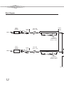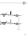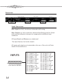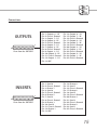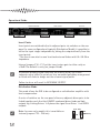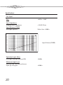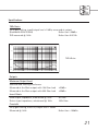
1
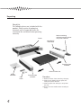
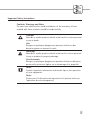
User
Guide
Driver in a Box
Legend
Crafted by AMEK
Designed by a
®
ure
ath
For many people, the achievement of sonic
perfection remains a dream...
One man has made it his life’s work to pursue this dream and
more than most, he has come close to making it a reality. Time
after time he has challenged conventions and rewritten the rules.
His hallmarks are an unwavering commitment to the detail of
circuitry design and a lifelong dedication to improvement.
His signature is a guarantee of audio excellence.
Many people point to his history.
Only Amek can bring you his future.
Introducing Pure Path® technology . . .
. . . Designed by Mr. Rupert Neve.
®
ure
ath
A Few Words from Rupert
“The ‘digital age’ imposes completely new
considerations for high performance analogue
audio design and brings both advantages and
disadvantages with it. These considerations cause
us to completely re-think how to get the very
best out of each new design, such as the
specifically designed transformers I have
incorporated into Pure Path® technology.
“The Pure Path® “Driver in a Box” - or DIB - is
the result of these careful considerations and
designed to meet the changing needs of
engineers and producers for a powerful yet compact outboard unit.
A transformer cannot usually be added successfully to an existing amplifier
although sometimes this is done in the field as a last resort to isolate
ground currents or other forms of interference. A transformer and the
stage which drives it (or into which it feeds) are an integral entity and must
be designed together.
The DIB is an extremely versatile unit which will find application in many
Studio situations where a robust, totally transparent isolating, levelling or
line driving amplifier is required.
When included in a digital sound path or added to the output of other
equipment of questionable performance, the DIB has the astonishing effect
of making the resulting sound much more "musical".
The DIB can be used as the heart of a "do-it-yourself" mixing system. If you
really want that "Original" sound, use the SILK button!
Used as part of a system with the CIB
the possibilities are considerable.
1
© 2000 Harman International Industries Ltd.
All rights reserved.
Parts of the design of this product may be protected by worldwide patents.
AMEK is a trading division of Harman International Industries Ltd.
Information contained in this manual is subject to change without notice and
does not represent a commitment on the part of the vendor. AMEK shall not be
liable for any loss or damage whatsoever arising from the use of information or
any error contained in this manual or through any mis-operation or fault in
hardware or software contained in the product.
No part of this manual may be reproduced, stored in a retrieval system,
transmitted in any form or by any means, electronic, electrical, mechanical,
optical, chemical, including photocopying and recording, for any purpose
whatsoever without the express written permission of AMEK.
It is recommended that all maintenance and service on the product should be
carried out by AMEK or it's authorised agents. AMEK cannot accept any liability
whatsoever for any loss or damage caused by service, maintenance or repair by
unauthorised personnel.
PART No: MANDIB Issue 1
Harman International Industries Ltd
Langley House
Third Avenue
Trafford Park
Manchester M17 1FG
United Kingdom
Tel: +44 (0) 161 868 2400
Fax: +44 (0) 161 873 8010
E-mail: [email protected]
Web: www.amek.com
2
®
ure
ath
Contents
A Few Words from Rupert . . . . . . . . . 1
Important Safety Instructions . . . . . 5-10
Replacing the Mains Fuse . . . . . . . 8
Mains Wiring . . . . . . . . . . . . . . 9
Installation . . . . . . . . . . . . . . . . . 11
Block Diagram . . . . . . . . . . . . . 12-13
Connections . . . . . . . . . . . . . . . . 14
Audio Connections . . . . . . . . . . 14
Operational Guide . . . . . . . . . . . . . 16
Principle . . . . . . . . . . . . . . . . 16
Inputs . . . . . . . . . . . . . . . . . 17
Phase . . . . . . . . . . . . . . . . . 17
Mute. . . . . . . . . . . . . . . . . . 17
Silk. . . . . . . . . . . . . . . . . . . 17
Level Meter . . . . . . . . . . . . . . 17
Insert Points. . . . . . . . . . . . . . 18
Distribution Mode . . . . . . . . . . 18
Specifications . . . . . . . . . . . . . 20-22
3
Unpacking
Check List
The following items are included with the
product. Please retain all packaging
materials until all expected items are
accounted for and found to be operating
correctly.
Packet containing:
4 off M6 mounting screws
4 off plastic washers
Carton
Moulded IEC
mains lead
Protective foam
materials
Driver in a Box Unit
Quality
Certificate
User
Guide
4
Protective foam
materials
Procedure
1. Remove all loose items from the packaging.
2. Slide the unit (along with the protective
foam parts) out of the box.
3. Slide the protective foam parts away from
the unit.
4. Refer to the User Guide before installing or
using.
®
ure
ath
Important Safety Instructions
Cautions, Warnings and Notes
For your own safety and to avoid invalidation of the warranty, all text
marked with these symbols should be read carefully.
Cautions
Hazards or unsafe practices which could result in severe personal
injury or death.
Avis
Dangers ou pratiques dangereuses pouvant résulter en des
blessures graves ou causant la mort.
Warnings
Hazards or unsafe practices which could result in minor personal
injury or product or property damage.
Avertissements
Dangers ou pratiques dangereuses pouvant résulter en blessures
personnelles mineures légères ou en dommages à la propriété.
Notes
Contain important information and useful tips on the operation
of your equipment.
Notes
Contiennent l’information de inportant et les pointes utiles sur
l’opération de votre équipement.
5
Important Safety Instructions
• Read these instructions.
• Keep these instructions.
• Heed all warnings and cautions.
• Follow all instructions.
• Do not place the apparatus on an unstable surface.
• Do not insert objects through any apertures.
• Do not use this apparatus near water.
• Unplug the unit before cleaning. Clean only with a damp cloth.
• Do not block any of the ventilation openings. Install in accordance with
the manufacturer's instructions.
• Do not install near any heat sources such as radiators, heat registers,
stoves or other apparatus including amplifiers or power supplies that
produce heat.
• Do not defeat the safety purpose of the polarised or grounding-type
plug. A polarised plug has two blades with one wider than the other. A
grounding-type plug has two blades and a third grounding prong. The
wider blade or the third prong are provided for your safety. When the
plug provided does not fit into your outlet, consult an electrician for
replacement of the obsolete outlet.
• Protect the power cord from being walked on or pinched particularly at
plugs, convenience receptacles and the point where they exit from the
apparatus.
• Avoid using mains outlets on the same circuits as air control systems or
other equipment that regularly switches on and off.
• Only use attachments /accessories specified by the manufacturer.
• Unplug this apparatus during lightning storms or when unused for long
periods of time.
6
®
ure
ath
Important Safety Instructions
• Refer all servicing to qualified service personnel. Servicing is required
when the apparatus has been damaged in any way, such as
- the power supply cord or plug is damaged
- liquid has been spilled or objects have fallen into the apparatus
- the apparatus has been exposed to rain or moisture
- the apparatus does not operate normally
- the apparatus has been dropped
Unplug the unit under these circumstances.
• Adjust only those controls that are covered by the operating
instructions.
• Use only the mains lead provided with the equipment . Other leads may
not have sufficient current rating.
• Do not operate this unit with the cover removed.
• The air intake and outflow holes must be inspected regularly and
cleaned if necessary to maintain good airflow throughout the unit. This
will be particularly important if the unit is used in a dusty environment.
• Use only with a cart, trolley, stand, bracket or table specified by the
manufacturer or supplied with the apparatus. When a cart or trolley is
used, exercise caution when moving the cart/apparatus combination to
avoid injury from top-over.
7
Important Safety Instructions
Replacing the Mains Fuse
Always observe the following:
CAUTION
RISK OF ELECTRIC SHOCK
DO NOT OPEN
AVIS:
!
RISQUE DE CHOC ELECTRIQUE NE PAS OUVRIR
CAUTION: To avoid the risk of fire, replace the mains fuse only with the
correct type and value fuse, as marked on the unit.
AVIS: Afin de reduire le risque de feu, remplacer seulement avec fusible de
meme typ, tel qu'indiqué sur l'appareil.
• Before changing the fuse, always remove the AC mains lead from the
connector.
• Using a flat blade screwdriver, press the fuse cap inwards gently and
twist anti-clockwise to release the cap. Replace it by reversing the
procedure.
• Check the fuse and replace if necessary; also check that the voltage
selection is correct for the mains supply voltage level before switching
the unit ON again.
• If the mains fuse fails repeatedly, this may be because an electrical
safety hazard exists. The unit must be taken out of service and referred
to the Amek dealer from whom the equipment was purchased.
8
®
ure
ath
Important Safety Instructions
Mains Wiring
Always observe the following:
CAUTION: THIS UNIT MUST BE EARTHED.
Under no circumstances should the mains earth be disconnected from the
mains lead.
AVIS: CET APPAREIL DOIT ÊTRE MIS À LA TERRE.
La mise à terre ne doit pas être débranchée du terminal principal sous
aucune circonstance.
The wires in the mains lead are coloured in accordance with the following
code:
Earth:
Neutral:
Live:
Green and yellow (Green/Yellow - US)
Blue (White - US)
Brown (Black - US)
As the colours of the wires in the mains lead may not correspond with the
coloured markings identifying the terminals in your plug, proceed as
follows:
• The wire which is coloured Green and Yellow must be connected to the
terminal in the plug which is marked with the letter E or by the earth
symbol.
• The wire which is coloured Blue must be connected to the terminal in
the plug which is marked with the letter N.
• The wire which is coloured Brown must be connected to the terminal in
the plug which is marked with the letter L.
Ensure that these colour codings are followed carefully in the event of the
plug being changed.
It is important to ensure that the correct mains fuse is fitted before
switching on the unit.
9
Important Safety Instructions
Servicing
Always observe the following:
CAUTION: The servicing instructions in this manual are for use by qualified
personnel only. To reduce the risk of electric shock, do not perform any
servicing other than that contained in the operating instructions unless you
are qualified to do so. Refer all servicing to qualified service personnel.
AVIS: Les instructions de services contenues dans ce manuel sont pour
utilisation seulement par des professionels. Pour réduire le risque de choc
électrique, ne tentez aucune opération de service sauf celles contenues dans
le manuel d'opération a moins d'être qualifié pour le faire. Référez toute
réparation à un agent de service professionel.
There are no user serviceable parts in this product, refer all servicing to your
Amek approved distributor.
10
®
ure
ath
Installation
Mains Voltage Selection
This apparatus does not require any operating voltage adjustment. Refer to
the acceptable operating range markings on the unit.
Location
This product is designed and screened to minimise internal electromagnetic
emissions and provide immunity to external electromagnetic fields.
To reduce the risk of performance degradation due to external interference,
do not site this unit close to sources of strong magnetic fields such as
power supplies, power amplifiers, loudspeakers etc.
Rack Mounting
This product is designed to be rack mounted using the screws and washers
supplied to help preserve the finish of the facia panel.
The facia graphic layer is under-surface printed to provide a robust hard
wearing surface designed to last the life of the product in virtually any
operating environment.
It is highly recommended that additional rear or side supports are used in
conjunction with the facia panel fixings. This is particularly important
when the unit is mounted in a flight case or vehicle where vibration and
transit shocks can be expected.
Powering up and Clicks
Clicks may be heard from in/out switches when the product is powered up,
these will dissipate after approximately 10 minutes. This is perfectly normal.
Cleaning
Unplug the unit before cleaning. The product should be cleaned with a soft
brush around the controls. If the facia becomes dirty, use a damp cloth with
a little household soap to remove the dirt. DO NOT use solvent cleaners
under any circumstances or the facia may be permanently damaged and
warranty invalidated!
11
Block Diagram
INPUT
JUMPER
OPTIONS
INPUT 1
LINE
PHASE
REV
INSERT
OUT
IN
GAIN TRIM
-6dB to +14dB
MIX AMP
INSERT
SEND
RETURN
+10dB GAIN
JUMPER OPTION
DEFAULT = UNITY
INPUT
JUMPER
OPTIONS
INPUT 2
LINE
MIX AMP
PHASE
REV
GAIN TRIM
-6dB to +14dB
INSERT
SEND
RETURN
+10dB GAIN
JUMPER OPTION
DEFAULT = UNITY
LINK TO 3
12
®
ure
ath
METER 1
SILK
OUT
IN
MUTE
SILK
OUTPUT 1
OUTPUT LEVEL
TRIM PRESET
METER 2
SILK
OUT
IN
LINK 1-2
MUTE
SILK
OUTPUT LEVEL
TRIM PRESET
OUTPUT 2
POWER ON / DOWN
MUTE CONTROL
13
Connections
DISTRIBUTION MODE
POWER
INSERT ENABLE
INSERT POINTS
INPUTS 1-8
OUTPUTS 1-8
Audio Connections
Main Inputs are fully transformer balanced and floating.
Main Outputs are fully transformer balanced and floating and are fitted
with internal calibration trimmers to compensate for different load
conditions.
All Insert Sends and Returns are unbalanced.
* See Specifications for further details.
All inputs and outputs are terminated on the rear of the unit via 25 pin
female D-Sub connectors.
INPUTS
1
25
View from the OUTSIDE
14
Pin 1: Input 8 - HI
Pin 2: Chassis Ground
Pin 3: Input 7 - LO
Pin 4: Input 6 - HI
Pin 5: Chassis Ground
Pin 6: Input 5 - LO
Pin 7: Input 4 - HI
Pin 8: Chassis Ground
Pin 9: Input 3 - LO
Pin 10: Input 2 - HI
Pin 11: Chassis Ground
Pin 12: Input 1 - LO
Pin 13: N/C
Pin 14: Input 8 - LO
Pin 15: Input 7 - HI
Pin 16: Chassis Ground
Pin 17: Input 6 - LO
Pin 18: Input - HI
Pin 19: Chassis Ground
Pin 20: Input 4 - LO
Pin 21: Input 3 - HI
Pin 22: Chassis Ground
Pin 23: Input 2 - LO
Pin 24: Input 1 - HI
Pin 25: Chassis Ground
®
ure
ath
Connections
OUTPUTS
1
25
View from the OUTSIDE
INSERTS
1
25
View from the OUTSIDE
Pin 1: Outputs 8 - HI
Pin 2: Chassis Ground
Pin 3: Output 7 - LO
Pin 4: Output 6 - HI
Pin 5: Chassis Ground
Pin 6: Output 5 - LO
Pin 7: Output 4 - HI
Pin 8: Chassis Ground
Pin 9: Output 3 - LO
Pin 10: Output 2 - HI
Pin 11: Chassis Ground
Pin 12: Output 1 - LO
Pin 13: N/C
Pin 14: Output 8 - LO
Pin 15: Output 7 - HI
Pin 16: Chassis Ground
Pin 17: Output 6 - LO
Pin 18: Output 5 - HI
Pin 19: Chassis Ground
Pin 20: Output 4 - LO
Pin 21: Output 3 - HI
Pin 22: Chassis Ground
Pin 23: Output 2 - LO
Pin 24: Output 1 - HI
Pin 25: Chassis Ground
Pin 1: Send 8
Pin 2: Chassis Ground
Pin 3: Return 7
Pin 4: Send 6
Pin 5: Chassis Ground
Pin 6: Return 5
Pin 7: Send 4
Pin 8: Chassis Ground
Pin 9: Return 3
Pin 10: Send 2
Pin 11: Chassis Ground
Pin 12: Return 1
Pin 13: N/C
Pin 14: Return 8
Pin 15: Send 7
Pin 16: Chassis Ground
Pin 17: Return 6
Pin 18: Send 5
Pin 19: Chassis Ground
Pin 20: Return 4
Pin 21: Send 3
Pin 22: Chassis Ground
Pin 23: Return 2
Pin 24: Send 1
Pin 25: Chassis Ground
15
Operational Guide
DRIVER 4
DRIVER 2
DRIVER 1
DRIVER 3
DRIVER 6
DRIVER 5
DRIVER 8
DRIVER 7
Principle
The Pure Path® ‘Driver in a Box’ (DIB) comprises eight transformer coupled
line drivers and eight further transformer coupled line receivers, which can
be configured for use in a vast number of applications.
Primarily a unity gain device, the DIB provides immaculate drive for long
audio lines. Gain trim, ‘Silk,’ Mute and Phase Reverse controls are provided
on each channel. In its normal use, DIB’s eight line receivers feed directly to
the eight line drivers, however, the flexibility to allow an insert/breakout
connector to be switched into the circuit has been built in, permitting the
possibility of a greater complexity of application.
It’s use as a Line Driver is only the beginning. The DIB’s real strength lies in
its huge versatility and wide breadth of application. Possible other uses
range from traditional audio engineering tasks like Line Receiving and
Distribution Amplifying, to audio enhancement of a Mixer or DAW. DIB
even invites use for more advanced applications, such as a Mix Amplifier,
Fader Box or even as a ‘Do it Yourself’ mixer when used in conjunction with
the Pure Path® ‘Channel in a Box’.
All eight drivers are identical. For clarity, all functions are discussed for
drivers one and two only, since certain features operate on adjacent pairs.
16
®
ure
ath
Operational Guide
Inputs
Rotary gain trim controls are provided ranging from -6dB to +14dB around
a unity gain centre detent.
P1 - P8
LINE LEVEL
(DEFAULT)
Three sensitivity settings are provided via
internal jumpers allowing the DIB to be
configured as required when used in conjunction
with other Pure Path ® products. These are set
on jumpers P1 - P8.
+12dB
MIX
FRONT OF UNIT
Phase
Individual input phase switches are fitted to the facepanel. The phase of the
incoming signal can be inverted immediately after the transformer and
before the gain trim. This allows the phase corrected signal to be accessed
via the inserts if required.
Mute
Individual mutes are fitted with facepanel controls. The mutes operate on
the final outputs AFTER the transformers and are also linked to a power on /
power down system to eliminate system thumps during powering on/off
cycles.
Silk
Individual Silk switches are fitted with facepanel controls. This introduces a
single-sided transistor amplifier circuit, which emulates the sound of my
original designs.
Level Meter
The level meters have a display range of -30dB to +6dB (OVU =+4dBu) with
O/L indication at +18dBu and display output levels immediately prior to the
transformers and their associated internal calibration trims. This is
particularly useful, as it allows output compensation for different load
impedances without affecting the meter readings.
17
Operational Guide
DISTRIBUTION MODE
POWER
INSERT ENABLE
INSERT POINTS
INPUTS 1-8
OUTPUTS 1-8
Insert Points
Insert points are switched in/out in adjacent pairs via switches on the rear
panel. In some configurations (typically Distribution Mode) it is possible to
utilise the input stages independently, taking the outputs directly from the
insert points.
* The inserts can also be used to attach external faders with 5k-10k Ohm
impedance.
Internal jumpers P10 - P17 set the insert return gain to either unity or
+10dB. The default is unity (no jumper fitted).
To preserve primary signal flow with the Inserts active, the D-Sub
connector must either be wired out to a normalled patchbay arrangement
or fitted with links to bridge out the relevant signal paths.
Failure to do so will result in NO SIGNAL OUTPUT.
Distribution Mode
This mode allows the DIB to be configured as a distribution amplifier with
level compensation.
A series of switches on the rear panel allow any adjacent driver pairs to be
linked together such that the LOWEST numbered driver feeds multiple
outputs e.g. Linking Drivers 1>2 places the signal from Driver 1 into BOTH
outputs.
P18 - P24
Note: In some early models, this is available on
internal jumpers P18 - P24 only.
ON
OFF
(DEFAULT)
FRONT OF UNIT
18
®
ure
ath
Operational Guide
Similarly, simultaneously linking 1>2, 2>3 and 3>4 places the signal in
Driver 1 to all four outputs.
In this mode, the linked outputs have redundant input stages which can be
re-used as required and accessed via the insert points.
* Refer to Insert Points for details.
Distribution Mode Multiple Configurations
Multiple simultaneous linked configurations can be set up such as:
• One master set of 1 in - 8 out
• Four sets of 1 in - 2 out
• A set of 1 in - 4 out with 4 single drivers
Many more permutations are possible, allowing the DIB to cater for every
eventuality.
19
Specifications
Line Input
Gain
-6dB to +14dB
Input Impedance
Bridging Input Impedance
>10,000 Ohms
Input Balance (CMRR)
Unity gain @1kHz
Better than -65dBu
DIB
0.0
JP-CMRR
AMPL(dBu) vs FREQ(Hz)
05 JUL 80 02:31:46
-10.00
-20.00
-30.00
-40.00
-50.00
Input Balance (CMRR)
-60.00
-70.00
-80.00
-90.00
-100.0
20
100
1k
10k
20k
Equivalent Input Noise
Unity gain setting, measured DIN
-98dBu
Maximum Input Level
Balanced and floating transformer
Input @ unity gain
+23dBu
20
®
ure
ath
Specifications
THD+Noise
Unity gain setting, input/output level +10dBu, measured at output
(Bandwidth 22Hz-22kHz)
Better than -98dBu
THD measured @ 1kHz
Better than 0.001%
DIB
JP-DIST
THD+N(%) vs FREQ(Hz)
05 JUL 80 02:20:00
0.5
0.1
THD+Noise
0.010
0.001
.0005
20
100
1k
10k
20k
Outputs
Maximum Output Level
Balanced and floating transformer
Measured at the Main output with 10k Ohm load
Measured at the Main output with 600 Ohm load
+23dBu
+22dBu
Insert Points
Send output impedance, unbalanced @ 1kHz
Return input impedance, unbalanced @ 1kHz
50 Ohm
100k Ohm
Crosstalk
Unity gain setting, Insert IN, output level +10dBu
Measured @ 1kHz
Better than -100dBu
21
Specifications
Frequency Response
10k Ohm load impedance
600 Ohm load impedance
DIB
5.0000
JP-FREQ
10Hz (-0.5dB) - 200kHz (-2dB)
10Hz (-0.5dB)- 120kHz (-3dB)
AMPL(dBu) vs FREQ(Hz)
05 JUL 80 02:04:58
4.0000
3.0000
2.0000
1.0000
0.0
Frequency Response
-1.000
-2.000
-3.000
-4.000
-5.000
10
DIB
5.0000
JP-FREQ
100
AMPL(dBu)
1k
vs
10k
100k 200k
09 JUL 80 21:22:12
FREQ(Hz)
4.0000
3.0000
2.0000
Frequency Response
1.0000
100m
0.0
-1.000
-2.000
Loaded 600R with test cable
from 100m-1000m
(@100m intervals)
-3.000
1000m
-4.000
-5.000
10
100
1k
10k
100k 200k
• Test cable used - Vandamme 268-001 audio installation cable.
Capacitance <90pF/m core to core, <189pF/m core to screen.
22
®
ure
ath
Specifications
Power Requirements
AC ~ input 50-60Hz, 100V-240V
Max 30W
Dimensions
19” 1U rack unit
Depth including connectors
482mm x 44.5mm
382mm
Weight
5.75 kg
23
Notes
24
®
ure
ath
Warranty
1. Amek is a trading division of Harman International Industries Ltd.
End User means the person who first puts the equipment into regular operation.
Dealer means the person other than Amek (if any) from whom the End User
purchased the equipment, provided such a person is authorised for this purpose by
Amek or it’s accredited Distributor.
Equipment means the equipment supplied with this manual.
2. If within the period of twelve months from the date of delivery of the Equipment
to the End User it shall prove defective by reason only of faulty materials and/or
workmanship to such an extent that the effectiveness and/or usability thereof is
materially affected, the Equipment or the defective component should be returned
to the Dealer or to Amek and subject to the following conditions, the Dealer or
Amek will repair or replace the defective components. Any components replaced will
become the property of Amek.
3. Any Equipment or component returned will be at the risk of the End User whilst in
transit (both to and from the Dealer or Amek) and postage/shipping must be prepaid.
4. This warranty shall only be available if:
a) The Equipment has been properly installed in accordance with instructions
contained in Amek’s manual; and
b) The End User has notified Amek or the Dealer within 14 days of the defect
appearing; and
c) No persons other than the authorised representatives of Amek or the Dealer
have effected any replacement of parts, maintenance adjustments or repairs to
the Equipment; and
d) The End User has used the Equipment only for such purposes as Amek
recommends, with only such operating supplies as meet Amek’s specifications
and otherwise in all respects in accordance with Amek’s recommendations.
5. Defects arising as a result of the following are not covered by this Warranty:
Faulty or negligent handling, chemical or electro-chemical or electrical influences,
accidental damage, Acts of God, neglect, deficiency in electrical power, airconditioning or humidity control.
6. The benefit of this Warranty may not be assigned by the End User.
7. End Users who are consumers should note their rights under this Warranty are in
addition to and do not affect any other rights to which they may be entitled against
the seller of the Equipment.
International Headquarters
Langley House
3rd Avenue
Trafford Park
Manchester
M17 1FG
Tel: +44 (0) 161 868 2400
Fax: +44 (0) 161 873 8010
US Headquarters
1449, Donelson Pike
Airpark Business Centre 12
Nashville
TN37217
Tel: +1 888 286 9358
Fax: +1 615 360 0273
Los Angeles
2740, W Magnolia Blvd #102
Burbank
CA91505
Tel: +1 800 585 6875
Fax: +1 818 973 1622
Tokyo
3-5-14, Konan
Minato-ku
Tokyo
108-0075
®
ure
ath
Tel: +81 (0) 3 5707 0575
Fax: +81 (0) 3 5707 0599
AMEK
A Harman International Company
Serial No: