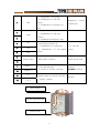
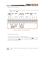
1
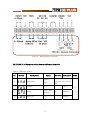
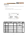
Vol. 0404E1
2004. 04. 15
Thyristor Power Regulators and
Remote Controller
USER MANUAL
CONTENTS
Caution for Your Safety
3
Warning and Caution
General
5
Feature
5
Installations and Wiring
6
3-1. Installation Guidelines
3-2. Wiring
Operating
9
4-1. Controller Description
4-1. Indicating
4-3. Changing Parameters
4-4. Parameters
4-5. Wiring and Operating According To Control Signal
Remote Control
14
5-1. Wiring for Remote Controller
5-2. TPR 3E PLUS Parameter Setting Connected Remote Controller
5-3. Remote Controller
Specification
18
6-1. Specification of TPR-3E PLUS
6-2. Specification of Remote Controller
6-3. Power Capacity and Fuse
2
━━━━━━━━━━━━━ Caution for Your Safety ━━━━━━━━━━━━━━
Please keep these instructions and review before using this controller.
This instruction manual uses WARNING and CAUTION as signal words
for safety.
WARNING
WARNING indicates a potentially hazardous situation which,
if not avoided, will result in death or serious injury.
CAUTION
CAUTION indicates a potentially hazardous situation which, if not avoided, will
result in minor or moderate injury and at other times will result in death or serious
injury. I may also be used to alert against unsafe practice.
WARNING indicates a potentially hazardous situation which, if not avoided,
will result in death or serious injury.
1. In case of using this unit with machineries (warehouse, medical equipments, vehicle, train,
airplane, nuclear power or safety device etc.), it requires installing fail-safe device.
• It may result in serious damage, fire or human injury.
2. Use a rated voltage to prevent damage or trouble.
• It may result in fire.
3. Check the number of terminal when connect each line and signal input.
• It may cause fire or trouble.
4. Do not turn on the power until the wiring completed.
• It may cause electric shock.
5. Do not repair, wiring or checkup when electric power on.
• It may cause electric shock.
6. Installation the controller where there is no dust, corrosive or explosive gas,
direct ray of the sun, mechanical vibration or shock present.
• It may cause fire or explosive.
7. This controller must be mounted on panel.
• It may cause electric shock.
8. Do not repair beyond of authorized technician.
• It may cause trouble.
3
CAUTION indicates a potentially hazardous situation which, if not avoided,
will result in minor or moderate injury and at other times will result in death or
serious injury. I may also be used to alert against unsafe practice.
Installation Guidelines
1.
Ensure the surrounding ambient operating temperature is between 0~50°C (32~122°F)
• It may cause fire or wrong operation.
2.
Altitude over 0~2000m use.
3.
Ensure the power supply for the controller does not fluctuate greatly. Main supply
voltage fluctuations not exceed ±10% of the normal voltage.
• It may cause fire.
4.
Install the controller where there is no dust, corrosive or explosive gas present.
• It may cause fire.
5.
Install the controller where there is no risk of mechanical vibration or shock.
• It might shorten the life cycle of the product or give an electric shock.
6.
This controller shall not be used outdoors.
• It might shorten the life cycle of the product or give an electric shock.
7.
When control signal wire connection, #20AWG (0.5mm2) should be used and screw
blot on terminal block with 0.74N.m strength.
• It may result in malfunction or error.
8.
Keep the controller away from high current and voltage circuits. The controller and
connection wires (esp. compensation conductors and RTD lead wires) should be kept
approximately 30cm(12”) away from high current or voltage circuits to limit the
possible affect of noise.
• It may cause display fluctuation or error.
9.
Do not use a place where temperature fluctuates or icing occurs.
• It may cause fire, explosive or error.
10.
In cleaning the controller, do not use water or an oil-based detergent.
• It might cause an electric shock or fire that will result in damage to the product.
11.
Do not inflow dust or dregs into inside of this controller.
• It may cause fire or trouble.
12.
Check the number of terminal when connect signal input line.
• It may cause fire or trouble.
13.
Installation category II
14. Pollution degree 2
4
1. General
TPR 3E PLUS is up-graded from TPR 3E series with advanced digital technology.
기존의 TPR 3E Series가 보유한 장점들(안정된 회로, 출력보호, 경보기능)을 계승하여 신뢰
성 있는 운전이 보장되고 여기에 디지털기술이 추가되어 현장에서 요구되어진 다양한 요구
에 대응 할 수 있다.
2. Feature
1) Operation by analog (4-20mA) or digital (RS 485) input signals
2) Indicating of analog (4-20mA) signal and output current (line R or T)
3) Automatic output-limit cognition of external volume or internal limit setting
4) Various alarm mode (over current, line failed, Un-load, over-temp. load unbalance)
5) Relay alarm output
6) Programmable Soft start
7) Anti-fluctuation by input filtering function
8) Easy alarm confirm by built-in buzzer
9) Output current limit function
10) Built-in watchdog timer
11) RS-485 interface (MODBUS® protocol) (Optional)
12) Remote control function by Remote Controller (Optional)
13) Compact Size
Note) TPR 3E PLUS can be replacement with TPR 3E and if you don’t use function,
don’t need parameter setting.
5
3. Installations and Wiring
3.1 Installation Guidelines
1) Ensure the surrounding ambient operating temperature is between 0~50℃.
2) Ensure the power supply for the unit does not fluctuate greatly.
3) Install the unit where there is no dust, corrosive or explosive gas present.
4) Install the unit where there is no risk of mechanical vibration or shock.
5) Keep the unit away from susceptible instruments by high current and voltage circuits.
The unit and connection wires (esp. medical instruments, controller and measurement
instruments or computers) should be kept approximately 30cm (12”) away from
susceptible instruments by high current and voltage circuits to limit the possible affects of
noise.
3.2
Wiring
1) Power
Prior to applying power, ensure the supply voltage is connected to the correct terminals as
ordered specification or marked on the electrical connection diagram.
Connect the power
supply voltage to input line terminals.
Tighten the power connections correctly. Poor tightening can lead to incorrect operation of the
unit and can have serious consequences on the installation.
All capacity is necessary to
connect the power cables using round lugs. See table 1.
Note) Keep the connection line does not shifting R, S and T.
Table 1. Line Input, Output Terminals
Symbol
Description
R
Input of line R
Operation
Note
Keep the connection
line does not shifting
S
Input of line S
T
Input of line T
Input power line
6
R, S and T.
U
Output of line R
V
Output of line S
W
Output of line T
Output power line to
load
2) Wiring for control signals
The control signals terminals are located at the front left of the unit.
They are used to connect:
-the control signal 4~20mA and the run contact
-the external V.R and the alarm output contact
-the interface terminals and power supply
Figure 1. Control signal terminal block
Note 1) Keep isolated between control signal line and power line.
Note 2) Ensure the power supply output voltage (+, -) for the remote
controller does not shortage.
Table 2. Control signal terminal
Position
1
2
Name
Assignment
Control signal
input (-)
Control signal
4-20mA analog input.
Input impedance is 250Ω.
input (+)
7
Note
1. Supplement +12V power.
2. Suitableness for ON-OFF
3
REF
control.
3. Suitableness for external V.R.
Supplement
current
is 40mA max.
input.
Output enables or disable.
4
1. Suitableness for ON-OFF
RUN
control.
5
2. Suitableness emergency stop.
6
G1
7
G2
8
G3
Connecting external V.R.,
1. Suitableness for output limit
V. R.: 1kΩ 1W
2.
A-type.
Suitableness
for
non-signal
control.
9
Alarm output
Relay alarm contactor
250Vac 3A (R load)
1. RS-485 Interface
Optional
2. Connect to remote controller
MODBUS® Protocol
10
11
RS485 (-)
12
RS485 (+)
13
V cc -
14
V cc +
Power supply for remote controller
(+9VDC, 200mA)
Input power
Control signal terminal
Output power
8
Optional
4. Operation
4.1 Controller Description
4.2 Indicating
Upon connecting power the unit is in a state of automatic operation and the input
signal or load current capacity is indicated on the front display.
If press [ENT] Key more than 2 second change display to input signal and load current
capacity R and T line.
Top LED is control signal input sign. (Unit=%)
Middle LED is load current capacity sign of line R. (Unit=A)
Bottom LED is load current capacity sign of line T. (Unit=A)
4.3 Changing Parameters
The set value can be changed by using [▲], [▼] and [ENT] key.
1) If press the [PAR] key, shift input signal to [PAS] for password input.
2) Pass value can be changed by using the increase[▲] and decrease[▼] key on
displayed PAS display.
3) After changing the value of a password, the right decimal point blinks, indication
9
the parameter has not been accepted.
4) By pressing [ENT] key this value is accepted and entered into EEPROM
(nonvolatile memory). When the accepted the decimal point disappears.
Enter password to access parameters setting group. Password is “5”.
Enter password to access interface parameters setting group. Password
is “15”.
5) If pressing [PAR] key, can be select each parameters when entered pass value.
6) Set parameter value after select using parameter.
7) Once finished changing parameter values, pressing [PAR] key for more than 2
seconds returns the controller to normal operation and the process value will be
displayed. Waiting approximately 80 seconds without pressing the key will return the
meter to normal operation as well.
4.4 Parameters
See table no. 3 for setting parameters.
Table 3.
No.
Parameter list
Symbol
Setting Data
Range
Operation
PASS
Changeable display of
0
-
Indicating
input signal or load
current by [ENT] key.
1
PASS number
Disable
2
Output limit high
0~100%
connected
when
external
VR.
3
4
None
Load
current
high
Soft Start time
limit
5~240A
1~250 sec.
10
If set to ‘0’ stop the
function.
5
Operation
5
for
ALm: Alarm only
over
OFF: Cut off output
current limit alarm.
Operation
6
for
Cnt: Output control
line
ALm: Alarm only
failed alarm.
Operation
7
OFF: Cut off output
for
over
ALm: Alarm only
temperature alarm.
OFF: Cut off output
Input Filter
8
0~10 sec.
Wait time for un-load
9
alarm.
Operation for internal
10
buzzer.
11
Select input
12
Address for interface
Delay
14
time
interface
0~254 sec.
OFF, ON
Against for fluctuation
If set to ‘0’ stop the
function.
OFF: Turn off
On: Turn on
Analog,
AnA: Analog (4~20mA)
Interface
COm: Interface
0~31
RS 485 address
2400, 4800, RS 485 speed
Speed for interface
13
5
15
9600bps
for
1~4
Delay time for reply
4.5 Wiring and Operating According to Control Signal
1) 4~20mA Current Input Signal
This is frequently used operation for control. Control signal is 4~20mA dc current.
Maximum output voltage is limited by external V.R or OUt parameter value.
Note 1) In case of connect external V.R, keep the terminals number.
Note 2) If connect external V.R, at G1, G2, and G3 terminal, disable internal parameter
OUt automatically.
11
Figure 2. Wiring for current input signal
2) ON-OFF Contact Input Signal
Output will be un-continuous ON-OFF by dry contact signal.
Maximum output voltage limit by output limit parameter [OUt] or external V.R.
Figure 3.
Wiring for contact input signal
12
3) Manual control by external V.R
Output power will be control by turn angle of output limit V.R or output limit
parameter (Symbol: OUt).
Figure 4.
Wiring for non-control input signal
4) RS 485 Interface (Optional)
TPR-3E PLUS will be control by RS-485 interface signals.
Apply power to the TPR-3EPLUS and go to parameter (Symbol: Smd). Set up the
control signal input (Symbol: COm). Refer to the TPR-3E PLUS interface manual for
instructions on using interface.
Note) If control signal input selected interface, current signal control will be
disable.
13
Figure 5.
Control by RS 485 Interface
5. Remote Control (Optional)
원격지시조절기(Remote Controller) 를 사용하면
TPR의 통신기능을 이용하여 원거리
에서도 운전에 필요한 각 변수를 변경 할 수 있고 운전상태를 확인 할 수 있다. 또한
패널 외부의 암페어메타 기능을 수행할 수 있다.
5.1
Wiring for Remote Controller
1) Short distance installation
In case of Install distance is less than 10m: Use main unit power. (Terminal Vcc)
2) Long distance installation
In case of install distance is more than 10m till 1200m: Select remote controller
power option. (90-240VAC, 50/60Hz)
14
Figure 7.
Wiring Remote Controller
5.2 TPR-3E PLUS Parameter Setting Connected Remote Controller
Table 5. Parameter Setting
No.
11
Symbol
Setting Data
Select input
12
Address
13
Speed
14
Delay time
Range
Analog,
COm
0~31
2400, 4800,
9600bps
1~4
15
Set Value
Refer
Description
to
set
remote
Controller
for
control
PASS
type
1
No. 1
96
9600bps
1
Default
15
5.3 Remote Controller
All remote controller functions are almost same with main unit controller function
except below.
1) Reset key function from front panel
2) Fixed interface parameters: Address; 1, Speed; 9600 BPS, Delay Time; 1
Figure 6. Front of Remote Controller
Table 4. Remote Controller Parameter List
No.
Symbol
Setting Data
Range
Operation
PASS
Changeable display of
0
-
Indicating
input signal or load
current by [ENT] key.
1
PASS number
Disable
2
Output limit high
0~100%
connected
when
external
VR.
3
4
None
Load
current
high
Soft start time
limit
5~240A
1~250 sec.
16
If set to ‘0’ stop the
function.
5
5
6
7
Operation
for
ALm: Alarm only
over
OFF: Cut off output
current limit high
Operation
for
Cnt: Output control
line
ALm: Alarm only
failed
Operation
OFF: Cut off output
for
over
ALm: Alarm only
temp.
OFF: Cut off output
8
Input filter
0~10 sec.
9
Wait time for un-load
0~254 sec.
10
Operation for internal
buzzer
11
Remote set value
12
Select input
5
OFF, ON
Against for fluctuation
If set to ‘0’ stop the
function.
OFF: Disable
On: Enable
0~100%
Analog,
AnA:Analog (4~20mA)
COm
COm: Interface
15
Note) If set to the ‘Com’ on parameter no 12, TPR output will control by the
remote set value of parameter no. 11.
17
6. Specification
6.1 Specification of TPR 3E PLUS
Voltage: One of AC 220V, 380V, 440V (AC 100V, 110V, 120V, 200V, 240V,
400V are made by order) . ±10%
Cycle: 50/60Hz
Current capacity: 35A, 50A, 80A, 100A, 120A, 150A, 190A, 240A, 500A.
(in case of ambient temperature is 50℃ or less)
Control Mode: Phase angle
Input Signal: DC4~20mA (Input impedance 250Ω), ON-OFF dry contact,
Non-signal (1kΩ VR), Interface (RS485 MODBUS Protocol)
Output: Maximum 97% of input voltage
Load: All resistance loads. Primary of transformer
Interface Protocol: RS 485. MODBUS®
Operating Temperature: 0~50℃
Cooling: Under 100A: Natural Cooling
Above 120A: Fan
Alarms: Over Current, Partial Line Failure, Load Unbalance, Unload,
Thyristor Overheating.
Alarm Output: AC 250V 1A (R Load)
Insulation Test: Between Power Terminal and Case AC 500V 50MΩ or
more
Puncher Test: Between power terminal and case AC 2000V. 1 min.
Dimension: 35A, 50A – 190(W) X 280(H) X 190(D) (mm)
80A, 100A - 240(W) X 350(H) X 240(D) (mm)
120A~240A - 300(W) X 350(H) X 240(D) (mm)
6.2 Specification of Remote Controller
Input: Direct communication with TPR-3E PLUS (Fixed Address 1, Speed
9600bps, Delay Time 1)
Max. Install Distance: In case of using main unit power; 10m or less
In case of built-in power board; 1200m max. (Optional)
Display Parameter: Input signal (%), R and T Φ output current (A)
Dimension: 96(W) X 48(H) X 100(D) (mm)
18
6.3 Power capacity and fuse model
(Note. cosθ =1)
Power Capacity and used fuse
Ampere
Model
220V
(A)
kw
TPR 3E PLUS
380V
Fuse
kw
Fuse
440V
kw
Fuse
35
13
JR 31-40
23
JR 61-40
26
JR 61-40
50
19
JR 31-60
32
JR 61-60
38
JR 61-60
80
30
JR 32-100
52
JR 62-100
60
JR 62-100
100
38
JR 32-120
65
JR 62-120
76
JR 62-120
120
45
JR 32-150
78
JR 63-150
91
JR 63-150
150
57
JR 33-180
98
JR 63-180
114
JR 63-180
190
72
JR 36-200
125
JR 66-200
144
JR 66-200
240
91
JR 36-250
157
JR 66-250
182
JR 66-250
Note 1) Use only rapid fuse for semiconductor.
Note 2) Exhortation capacity is 60% or less than of maximum capacity.
Note 3) Equation three phase power: P(kw) = √3 X V X I X cosθ
Note) This manual is subject to change without notice.
SANUP ELECTRIC CO.
Headquarter and Factory: 240-42, Euijeongbu 2 dong Euijeongbusi Kyoungkido, Korea
Tel. 0082-31-876-4641~3 Fax. 0082-31-876-4640
Seoul Office 1: 42, Jangsa dong Jongrogu Seoul, Korea
Tel. 0082-2-2265-2298, 2272-0785 Fax. 0082-2-2272-9450
Seoul Office 2: Ga-1612, Central Distribution Center Gurodong Gurogu Seoul, Korea
Tel. 0082-2-2689-0648, 0658 Fax. 082-2-2689-0043
http://www.sanup.com
email: [email protected]
19