1
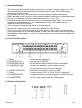
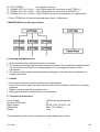
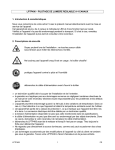
LPTT1202 – 12-CHANNEL TOUCH PANEL CONTROLLER
1. Introduction
Thank you for buying the LPTT1202 ! Please read the manual carefully before bringing this
device into service.
This device features 12 channels (24 touch sensors), flash and hold modes, two-colour LED
indicators, 3 synchronous chase controls, chase speed control and 6 signal output connectors
(one 25-pin SUB-D connector & five 8-pin DIN connectors).
Make sure that the device was not damaged in transit. If the device is damaged, you should
contact your dealer and postpone installation of this device.
2. Safety Instructions
Be very careful when installing the device : touching
live wires can cause life-threatening electroshocks.
Do not touch the device during operation as the housing heats up
Protect this device against rain and moisture
Unplug the supply cable before you open the housing
• a qualified technician should install and service this device.
• damages caused by disregarding certain guidelines in this manual are not covered by the
warranty and the dealer will not accept responsibility for the ensuing defects or problems.
• do not switch the device on immediately if it has been exposed to changes in temperature.
Protect the device against damage by leaving it switched off until it has reached room
temperature.
• this device falls under protection class I. It is essential, therefore, that the device be earthed.
Have this device installed by a qualified technician.
• make sure that the available voltage does not exceed the voltage stated in the specifications
of this manual.
• do not crimp the power cord and protect it against damage from sharp edges. Ask an
authorised dealer to replace the cord if necessary.
• always disconnect the device from the mains when it is not in use or when you wish to clean
it. Only handle the power cord by the plug. Never pull out the plug by tugging the power cord.
• Do not look directly into the light source as sensitive people may go into epileptic seizure if
they do.
• Be aware that damages caused by user modifications to the device are not covered by the
warranty. Keep the device away from children and unauthorised users.
LPTT1202
1
GB
3. General Guidelines
• This device is a light controller for professional use on stages, in discos, theatres, etc. This
device should only be operated with an alternating current of max. 230Vac/50Hz and is
designed for indoor use only.
• Do not shake the device. Avoid brute force when installing or operating the device.
• Select a location where the device will be protected against extreme heat, moisture and dust.
• Do not use or transport the device under temperatures < 5°C or > 35°C.
• Familiarise yourself with the functions of the device before actually using it. Do not permit
operation by unqualified people. Any damage that may occur, will probably be due to
unprofessional use of the device.
• Use the original packaging if the device is to be transported.
• Note that all modifications of the device are forbidden for safety reasons.
• Do not remove the serial number sticker from the device as doing so will void the warranty.
Only use the device for its intended purpose. All other uses may lead to short-circuits, burns,
electroshocks, lamp explosion, crash, etc. Using the device in an unauthorised way will void
the warranty.
4. Front Panel Description
1.
2.
3.
4.
5.
SENS
POWER SWITCH
POWER INDICATOR
FLASH TOUCH KEY
HOLD TOUCH KEY
6. OUTPUT INDICATOR
7. CHASE
8. CHASE INDICATOR
9. CHASE SPEED
: touch sensitivity adjustment
: turns the device ON/OFF
: this red indicator lights when the device is activated
: activates the channel in question when touched
: the channel in question is activated when the key is touched
and is deactivated when the key is released
: indicates if the channel is active (red LED)
: 3 buttons to select CH1-4, CH5-8, CH9-12 respectively.
: indicates whether the group of 4 channels is selected as an
output in the current chase (red LED)
: turn the rotary knob to adjust the chaser speed
5. Back Panel Description
LPTT1202
2
GB
10.
11.
12.
13.
EXT. POWER
SIGNAL OUT (2 x 6 CHs)
SIGNAL OUT (3 x 4 CHs)
SIGNAL OUT (1 x 12 CHs)
:
:
:
:
for operation test only
8-pin DIN sockets for connection to a LPTP406 (*)
8-pin DIN sockets for connection to LPTP406 (*)
25-pin SUB-D connector for connection to a power pack
(*) The LPTP406 is a 4-channel patchable power pack, 10A/channel
CONNECTIONS (see also figure above)
6. Cleaning and Maintenance
1. All screws should be tightened and free of corrosion.
2. The housing, mounting supports and connections should not be modified or tampered with
e.g. do not drill extra holes in mounting supports, do not change the location of the
connections, …
3. The electric power supply cables should be undamaged. Have this device installed by a
qualified technician.
7. Caution
• Disconnect the device from the mains prior to maintenance.
• Use a moist cloth to clean the device and avoid the use of alcohol or solvents for cleaning
purposes.
• Replace a blown fuse with an identical one.
• Spare parts should be ordered with your local dealer.
8. Technical Specifications
Power Supply
Number of Channels
Signal Output
Dimensions
Weight
+20Vdc through power pack
12
ON DC +10V; OFF DC +0V
482 x 75.5 x 88mm
1.3kg
The information in this manual is subject to change without prior notice.
LPTT1202
3
GB