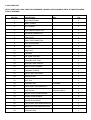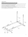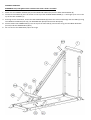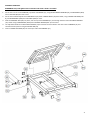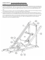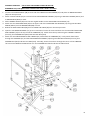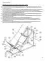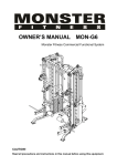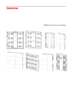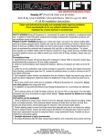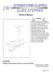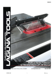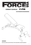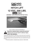
1
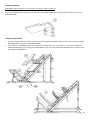
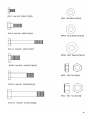
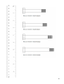
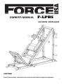
OWNER’S MANUAL F-LPHS LEG PRESS / HACK SQUAT CAUTION! Read all precautions and instructions in this manual before using this equipment. 1 ASSEMBLY MANUAL FOR: FORCE USA LEG PRESS / HACK SQUAT F-LPHS BEFORE YOU START Remove all parts from the packaging and separate and count each various component to ensure everything has been correctly provided. Follow the instructions and consult both the individual assembly pages and the overall expanded views of the equipment It is the owner’s responsibility to ensure that all users of this unit have read the owner’s manual and are familiar with the safety precautions. SAFETY PRECAUTIONS Highly recommended for two or more people to assemble the equipment to avoid injury. Assemble the equipment on a flat level surface. Consider placing a mat under the equipment to protect your floor. Wear appropriate footwear and clothing during assembly and use. Only tighten nuts and bolts by hand until the whole equipment is assembled Do not allow children and pets to be unsupervised around the assembly or usage of this equipment. Ensure all parts are in full working order before use. Only one person should use the machine at any one time. Do not use the equipment outdoors or around water. Keep hair, fingers or clothing away from moving parts. Only use attachments recommended by the manufacturer. Never operate if any parts are not functioning correctly. Always correctly stretch and warm up before using the equipment. Stop immediately if you experience any pain, dizziness or nausea. See a doctor at once. PLEASE NOTE: Descriptions of pieces as LEFT and RIGHT are from the point of view of standing behind the equipment facing towards the front. BEFORE STARTING ANY EXERCISE PROGRAM, CONSULT YOUR DOCTOR. ESPECIALLY IF YOU ARE OVER THE AGE OF 35 OR HAVE PRE-EXISTING HEALTH PROBLEMS. READ ALL INSTRUCTIONS BEFORE ASSEMBLING OR USING ANY FITNESS EQUIPMENT. FORCE USA FITNESS EQUIPMENT ASSUMES NO RESPONSIBILITY FOR PERSONAL INJURY OR PROPERTY DAMAGE SUSTAINED BY OR THROUGH THE USE OF THIS PRODUCT. SAVE THESE INSTRUCTIONS. 2 F-LPHS PARTS LIST NOTE: SOME PARTS MAY COME PRE-ASSEMBLED, IN WHICH CASE CONTINUE ONTO THE NEXT REQUIRED STEP OF ASSEMBLY KEY NO. DESCRIPTION SPEC Q'ty 1 BASE MAIN FRAME 2 2 RIGHT UPRIGHT 1 3 LEFT UPRIGHT 1 4 FRONT BASE CONNECTOR 1 5 REAR BASE CONNECTOR 1 6 STEEL PLATE 2 7 FRONT TOP CONNECTOR 1 8 SEAT PAD SUPPORT 1 9 LEFT RAIL 1 10 RIGHT RAIL 1 11 CARRIAGE 1 12 LEG PRESS FOOTREST 1 13 CARRIAGE STOP TUBE 1 14 SHOULDER PAD SUPPORT 1 15 WEIGHT PLATE CARRIER 1 16 CARRIAGE STOPPER 2 17 SQUAT FOOT PLATFORM 1 18 BACKREST PAD 1 19 SEAT PAD 1 20 CARRIAGE AXLE 21 SQUAT FOOT PLATFORM AXLE 22 STEEL SLEEVE 23 WEIGHT PLATE STORE HOLDER 6 24 RUBBER STRAP HOLDER 8 25 BACKREST PAD HOOK 1 26 OUTER FOOT PLATFORM ADJUSTER 1 27 INNER FOOT PLATFORM ADJUSTER 1 28 SHOULDER PAD 2 L=555MM 1 1 Diameter=48mm 2 3 29 HANDLE SLEEVE 6 30 INNER CAP 31 BIG WHEEL 4 32 BIG WHEEL BEARING 8 33 SMALL WHEEL 4 34 BIG POP PIN 1 35 INNER CAP 36 SMALL POP PIN 37 INNER CAP Dia=25mm 16 38 SLEEVE Dia=48mm 8 39 BUMPER CAP Dia=25mm 10 40 SPRING CLIP Dia=25mm 8 H6-1 HEX HEAD BOLT M6x10mm 2 H8-3 HEX HEAD BOLT M8x25mm 2 H8-12 HEX HEAD BOLT M8x70mm 7 H10-2 HEX HEAD BOLT M10x20mm 12 H10-8 HEX HEAD BOLT M10x50mm 4 H12-12 HEX HEAD BOLT M12x70mm 2 H12-13 HEX HEAD BOLT M12x75mm 14 H12-14 HEX HEAD BOLT M12x80mm 2 H12-18 HEX HEAD BOLT M12x100mm 2 H12-19 HEX HEAD BOLT M12x105mm 8 W8 WASHER M8 9 W10 WASHER M10 20 W12 WASHER M12 56 N10 NUT M10 4 N12 NUT M12 28 F50x50mm F50X70mm 13 1 1 NOTE: SOME PARTS MAY COME PRE-ASSEMBLED, IN WHICH CASE CONTINUE ONTO THE NEXT REQUIRED STEP OF ASSEMBLY 4 ASSEMBLY DIAGRAM 1: REMEMBER: Only hand tighten all nuts and bolts until whole F-LPHS is assembled 1. Ensuring correct orientation, attach the REAR BASE CONNECTOR (5) to a BASE MAIN FRAME (1) using a STEEL PLATE (6), two HEX BOLT M12X75 (H12-13), four WASHER M12 (W12) and two NUT M12 (N12) 2. Attach the FRONT BASE CONNECTOR (4) to the same BASE MAIN FRAME (1) and the RIGHT UPRIGHT (2) using three HEX BOLT M12X75 (H12-13), six WASHER M12 (W12) and three NUT M12 (N12) 3. Attach the other BASE MAIN FRAME (1) to the free side of the REAR BASE CONNECTOR (5) using a STEEL PLATE (6), two HEX BOLT M12X75 (H12-13), four WASHER M12 (W12) and two NUT M12 (N12) 4. Attach the LEFT UPRIGHT (3) to the FRONT BASE CONNECTOR (4) and the BASE MAIN FRAME (1) using three HEX BOLT M12X75 (H12-13), six WASHER M12 (W12) and three NUT M12 (N12) 5 ASSEMBLY DIAGRAM 2: REMEMBER: Only hand tighten all nuts and bolts until whole F-LPHS is assembled 1. Attach the two HANDLE SLEEVES (29) and the INNER CAP 50X70 (35) onto the SEAT PAD SUPPORT (8) 2. Connect the LEFT RAIL (9) over the socket on the top of the left BASE MAIN FRAME (1). It will angle up to rest on the top of the LEFT UPRIGHT (3) 3. Ensuring correct orientation, attach the SEAT PAD SUPPORT (8) above the socket and through the LEFT RAIL (9) using two HEX BOLT M12X105 (H12-19), four WASHER M12 (W12) and two NUT M12 (N12) 4. Slot the FRONT TOP CONNECTOR (7) into the top of the LEFT RAIL (9) and connect using two HE X BOLT M12X105 (H12-19) and two WASHER M12 (W12) 5. Do not connect the RIGHT RAIL (10) at this stage 6 ASSEMBLY DIAGRAM 3: REMEMBER: Only hand tighten all nuts and bolts until whole F-LPHS is assembled 1. On the four corners of the CARRIAGE (11) attach a BIG WHEEL (31), using two BIG WHEEL BEARINGS (32), a WASHER M12 (W12) and a NUT M12 (N12) for each corner. 2. On the four brackets adjacent to the BIG WHEELS (31) attach a SMALL WHEEL (33) from below, using a HEX BOLT M10X50 (H10 8), two WASHER M10 (W10) and a NUT M10 (N10) for each. 3. Slide the CARRIAGE AXEL (20) into place, over the top of the CARRIAGE (11) and through the base of the LEG PRESS FOOTREST (12). Attach using a WASHER M10 (W10) and a HEX BOLT M10X20 (H10-2) at each end. 4. The adjustable stand for the LEG PRESS FOOTREST (12) should slot into the bracket in the centre of the CARRIAGE (11) and should be held in position using the BIG POP PIN (34) 5. Insert an INNER CAP 50X50 (30) into each open end of the CARRIAGE (11) 7 ASSEMBLY DIAGRAM 4: USE AT LEAST ONE PARTNER TO HELP IN THIS STEP REMEMBER: Only hand tighten all nuts and bolts until whole F-LPHS is assembled 1. Connect the CARRIAGE STOP TUBE (13) to the LEFT RAIL (9) using a HEX BOLT M12X100 (H12-18), two WASHER M12 (W12) and a NUT M12 (N12). There are multiple positions to choose from to connect the CARRIAGE STOP TUBE (13) and you should select one to match your height and therefore how low you wish the LEG PRESS FOOTREST (12) to slide. 2. Ensuring correct orientation, position the assembled CARRIAGE + FOOTREST (11&12) into the LEFT RAIL (9) and then slot the RIGHT RAIL (10) into place, mirroring the positioning of the LEFT RAIL (9) 3. Starting from the bottom, connect the RIGHT RAIL (10) under the bracket of the SEAT PAD SUPPORT (8) using two HEX BOLT M12X105 (H12-19), four WASHER M12 (W12) and two NUT M12 (N12). Next connect the RIGHT RAIL (10) over the CARRIAGE STOP TUBE (13) using a HEX BOLT M12X100 (H12-18), two WASHER M12 (W12) and a NUT M12 (N12). Finally connect the top of the RIGHT RAIL (10) to the FRONT TOP CONNECTOR (7) using two HEX BOLT M12X105 (H12-19) and two WASHER M12 (W12) 8 ASSEMBLY DIAGRAM 5: USE AT LEAST ONE PARTNER TO HELP IN THIS STEP REMEMBER: Only hand tighten all nuts and bolts until whole F-LPHS is assembled 1. Connect two SLEEVES 48mm (38) to each side of the WEIGHT PLATE CARRIER (15) and place an INNER CAP 50X50 (30) over the open end 2. Attach a STEEL SLEEVE (22) to each end of the SHOULDER PAD SUPPORT (14) using a HEX BOLT M10X20 (H10-2) and a WASHER M10 (W10) o n each. 3. Slide a HANDLE SLEEVE (29) onto the two angled handles on the SHOULDER PAD SUPPORT (14) 4. Attach the two SHOULDER PADS (28) to the upper side of the SHOULDER PAD SUPPORT (14) using two HEX BOLT M8X70 (H8-12) and two WASHER M8 (W8) on each 5. Behind the SHOULDER PADS (28) place an INNER CAP 50X50 (30) over the two open ends. 6. Open the LEG PRESS FOOTREST (12) up to its maximum for ease of access and then slot the assembled SHOULDER PAD SUPPORT (14) on the top end of the CARRIAGE (11). Attach from the top side using two HEX BOLT M12X75 (H12-13), four WASHER M12 (W12) and two NUT M12 (N12) 7. Attach the assembled WEIGHT PLATE CARRIER (15) underneath the CARRIAGE (11). Firstly attach from below through the CARRIAGE (11) and the SHOULDER PAD SUPPORT (14) using two HEX BOLT M12X75 (H12-13), four WASHER M12 (W12) and two NUT M12 (N12). Secondly, attach from above through the centre of the CARRIAGE (11) using two HEX BOLT M12X70 (H12-12), four WASHER M12 (W12) and two NUT M12 (N12) 9 ASSEMBLY DIAGRAM 6: REMEMBER: Only hand tighten all nuts and bolts until whole F-LPHS is assembled 1. Attach five BUMPER CAPS (39) to each CARRIAGE STOPPER (16) and slide a HANDLE SLEEVE (29) onto the lower end of each. 2. Ensuring correct orientation, connect the CARRIAGE STOPPERS (16) onto the RAILS (9 &10) using a HEX BOLT M6X10 (H6-1) at the upper connection point. 3. Connect an INNER CAP 25mm (37) to each end of all eight RUBBER STRAP HOLDERS (24) and once assembled, slot them through the four appropriate holes at the top of the UPRIGHTS (2&3), clipping each positioned holder with a SPRING CLIP (40) 4. Slide a SLEEVE 48mm (38) onto all six WEIGHT PLATE STORE HOLDERS (23) and attach three to each side of the UPRIGHTS (2&3) using a HEX BOLT M10X20 (H10-2) and a WASHER M10 (W10) on each. 5. Connect the OUTER FOOT PLATFORM ADJUSTER (26) to the bracket on the top of the REAR BASE CONNECTOR (5) using a HEX BOLT M12X80 (H12-14), two WASHER M12 (W12) and a NUT M12 (N12) 6. Slot the INNER FOOT PLATFORM ADJUSTER (27) into the OUTER FOOT PLATFORM ADJUSTER (26) and connect using a SMALL POP PIN (36) at the desired height. 7. Attach an INNER CAP 50X50 (30) onto the four corners of the SQUAT FOOT PLATFORM (17) 8. Connect the lower edge of the SQUAT FOOT PLATFORM (17) to the BASE MAIN FRAME (1) by sliding the SQUAT FOOT PLATFORM AXEL (21) through the tube brackets and the PLATFORM (17) Attach using a HEX BOLT M10X20 (H10-2) and a WASHER M10 (W10) on each end. 9. Align the brackets under the SQUAT FOOT PLATFORM (17) with the top of the INNER FOOT PLATFORM ADJUSTER (27) and attach using a HEX BOLT M12X80 (H12-14), two WASHER M12 (W12) and a NUT M12 (N12) 10 ASSEMBLY DIAGRAM 7: REMEMBER: Only hand tighten all nuts and bolts until whole F-LPHS is assembled 1. Connect the BACKREST PAD HOOK (25) to the underside of the BACKREST PAD (18) using two HEX BOLT 8X25 (H8 -3) and two WASHER M8 (W8) ASSEMBLY DIAGRAM 8 & 9: 1. Position the SEAT PAD (19) in place and connect to the SEAT PAD SUPPORT (8) from underneath using three HEX BOLT 8X70 (H8-12) and three WASHER M8 (W8) 2. You can position the BACKREST PAD (18) in two positions depending on your current exercise – either slot it between the SHOULDER PADS (28) if you are doing squats (DIAGRAM 8) or slot it onto the SQUAT FOOT PLATFORM (17) for when you are doing leg press (DIAGRAM 9) 11 12 13 WARRANTY LIFETIME WARRANTY ON FRAME 5 YEARS ON CABLES AND PULLEYS Force USA, the Trusted Name in Strength Equipment™ was designed to be the best value strength equipment for home use and proudly set the benchmark for our home use equipment around the world. Offering one of the best warranties on the market for your peace of mind, each piece of Force USA strength equipment is hand crafted for quality and we use state-of-the-art production methods for our entire range. The Force USA range of strength equipment carries a Lifetime Structural Warranty along with 5 years cover on all cables and pulleys. This warranty applies to first owners and does not cover second hand equipment or re-sold equipment. This Force USA warranty covers only failures due to defects in structural, cables and pulleys and workmanship that occur during normal home use. It will not cover damage that occurs in transport/delivery or failure due to misuse, abuse, neglect, mis-application, alteration or improper assembly of the product. This warranty does not cover the use or failure of equipment in studio commercial applications. The replacement or repair provided for under the Force USA warranty is the responsibility of the user and the customer will be responsible for any freight charges applicable. Force USA will not be liable for any consequential damages or for breach of any implied warranty on the range of Force USA strength equipment. Force USA reserves the right to provide reconditioned parts and/or to request a return and repair existing defective parts on the Force USA product. VorTex by Force USA is a commercial grade upholstery used for all Force USA equipment. We use a high grade commercial vinyl with rip-stop mesh backing which helps prevent rips and tears. Force USA, the Trusted Name in Strength Equipment™ was designed to be the best value strength equipment for home use and proudly set the benchmark for our home use equipment around the world. 14