1
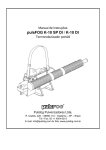
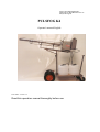
Frans Veugen Bedrijfshygiëne BV.
Pannenweg 329 6031 RK Nederweert NL.
[email protected]
PULSFOG K4
Operator's manual English
June 2004 - version 3.3
Read this operation manual thoroughly before use
Frans Veugen Bedrijfshygiëne BV
Operator’s manual Pulsfog K4
Contents:
NOTICE:
3
INTRODUCTION
3
TECHNICAL DATA
4
SAFETY PRECAUTION and INJURY PREVENTION
4
USER'S MANUAL
5
STARTING
DIRECTIONS ON STARTING
A. Preparation
B. Starting
C. Fogging
D. Quitting
E. In General
5
5
5
6
6
6
6
GRAPHIC EXPLANATION of the MACHINE
7
ELECTRIC IGNITION SCHEDULE
12
CARBURETOR and FLOAT
14
CROSS-SECTION of MEMBRANE FLOAT
16
AIR SUPPLY SCHEDULE
17
PARTLIST
18
MEMBRANE FLOAT PARTLIST
24
Safety instructions and accident prevention
25
2
Frans Veugen Bedrijfshygiëne BV
Operator’s manual Pulsfog K4
HAVE YOUR MACHINE CHECKED AND INSPECTED
BY A SPECIALIST
ONCE A YEAR
Notice:
The information in this operator’s manual can be altered without any previous notice. No rights can be derived
from this Operator’s manual.
Frans Veugen Bedrijfshygiene BV can not be held responsible for any damage or injuries that are the result of
misuse or use that does not correspond with the instructions in this operators manual.
Introduction:
The Pulsfog K4 is a thermal fogging machine. In the combustion chamber the fluid, that is to be fogged, is
transformed into fog. The machine works according to the jet-motor principle and has self-combustion. The K4 is
the biggest machine of the thermal fogging machine line of Pulsfog. The big capacity makes sure that a fog-range
of 120 meters* can be established. The K4 has a capacity that can vary from 60 till 150 ltr/h*.
* These values are dependent on the environment, the used fluid and the size of the sprayers.
3
Frans Veugen Bedrijfshygiëne BV
Operator’s manual Pulsfog K4
Technical Data:
* Weight: 45 kg
* Material: completely stainless steel 2 mm.
* Power: 125 HP / 79200 Kcal/h.
* Volume combustion chambers: 3 liters.
* Fog range low cultivation: 120 meters.
* Capacity: 60 - 150 ltr/h.
* Capacity of fuel tank: 20 ltr. (tank is removable)
* 2 fluid tanks: 2 x 30 ltr.
* Electric ignition 12 volts.
* 6 sprayers
* 3 carburetors
* Bio-system 2 separated fluid lines
Safety precautions and injury prevention:
Important: Read, understand and respect the following safety precautions before you start working with the
machine. Not respecting these safety rules can lead to a fire accident. The operators manual has to be thoroughly
read by the user, before he/she starts fogging with the machine.
•Always check if the machine is functional, when running stationary, before you actually start fogging.
•Never let the fogging machine run without supervision. The operator always has to be able to turn the fluid
lever closed if the machine should stop running.
•Never refill the fuel tank with fuel if the motor is still hot.
•Never put fuel in the fluid tanks
•There should never be smoking or open fire when you refill the tanks with a flammable fluid or when there are
reparations done on the fogging machine. The spark plug cap and the battery lid should always be detached when
the carburetor is opened.
•Do not fog in spaces where there can a dust explosion can occur or where there is a lot of dust in the air.
•Do not fog any fluids of which the combustion temperature is lower then 75 degrees Celsius.
•When fogging fluids of which the combustion temperature is higher then 75 degrees Celsius, only use fogging
equipment that provides an automatic turn off system of the fogging fluid or the machine has to have a double
cooling jacket.
•When fogging flammable fluids with a Pulsfog fogging machine you can only use the so called "O"-types or the
"BIO" type which has a separate water injection.
•Never fog more then 2.5 liters of a flammable fluid or a fluid on water base with less then 50% water, per 1000
(m3) space.
•Do not fog with flammable fluids in a pipe or tunnel without ventilation (explosion hazard). An exception is the
Pulsfog "BIO"-type that has a separated water injection.
4
Frans Veugen Bedrijfshygiëne BV
Operator’s manual Pulsfog K4
User's Manual:
Starting:
Before the first usage or the first usage after a long time or after the transportation of the machine over a big
distance, you have to take these following actions.
1.
Tighten all three of the six sided nuts on the three carburetors (pic. #1). Check this thoroughly after the
first time you used the device.
2.
Check if all fuel lines are attached correctly and if necessary tighten the tube holders.
3.
Tighten the carburetor caps on all three carburetors.
4.
Check if all sprayers are attached and tightened. Check this thoroughly after the first time you used the
device.
5.
If the fuel tank is full, check if the prescribed junction is closed properly. Immediately remove dust and
dirt from the joining, otherwise there will be interruptions in the fuel supply. Besides a loose tube causes
fire hazard (pic #3 and 4).
6.
Before the first time you use the device , the air flow out of the manometer has to be
opened. Open the door with the manometer. On top of the manometer is a rubber cap with a
tip. Cut off this tip to let air into the manometer.
backside of
manometer
Directions on starting:
A. Preparation:
1.
Attach the filled fuel tank to the machine (pic #2), fasten and then attach fuel tube (pic. #3 and 4). Make
sure the fuel tank has been filled for at least 3/4 with fuel.
2.
Turn the air supply notch at the tank closure at least 5 times to the left (pic. #5)
3.
Open fuel tap (pic. #5)
4.
Make sure that if the machine turns to the left or the right, it can not flip over with it's cart.
5.
Hook up 12V-battery
6.
Fill Bio-tank #1 (30, 60 or 100 liter) with water.
7.
Close the central closure
8.
Bring the junction with "normal tube" (plastic tube) and "single searcher" through the little hole and
close with the tank lid.
9.
Attach pressure tube (black rubber tube) to the air column.
10.
Attach water tube (without subscript) to the water connection (subscript "water") (pic. #6)
11.
Fill fluid tank #2 with the desired concentrate of the fluid that is going to be fogged (use funnel
with the sieve).
12.
Close central closure
13.
Bring the junction with "normal tube" (plastic tube) and "single searcher" through the little hole and
close with the tank lid.
14.
Attach pressure tube (black rubber tube) to the air column (subscript "air-solution") (pic. #6)
15.
Attach spray fluid tube (without subscript) to the spray fluid column (subscript "middle") (pic. #6)
16.
Place both tanks on the same level as the machine
17.
Secure all the tubes from both tanks to the machine so they do not
* pinch off
* touch any hot parts of the machine
* get any currency while fogging
The setup and filling of the tanks has to be done before you start the machine.
5
Frans Veugen Bedrijfshygiëne BV
Operator’s manual Pulsfog K4
B. Starting:
1.
2.
3.
4.
5.
Put on ear protection.
Open the right adjustable notch #2 till it is in starting position (white field on red arrow, pic. #8)
Push start button and slowly open at the same time the adjustable notch on the left #1, till the
machine starts. If it does not start (carburetor could be greasy), close adjustable notch on the left
and hold down the start button for approximately 10-20 seconds (blows carburetor clean). After
that repeat starting sequence as described above.
Open both of the adjustable notches evenly till the machine runs stationairy with deep humming
tones. The machine should not run with high humming tones, but with low ones and sometimes you
should hear "little explosions".
If necessary, tune with adjustable notch #3 on the carburetor (pic. #9)
C. Fogging:
Let the machine warm up a bit first and then start fogging after approximately 1 minute.
1.
First open the Bio-Fog tab (upper water tab) (pic. #6)
2.
The Bio-Fog tab stays open when the machine runs with full power
3.
After some seconds you open the fog-tap (lower spray fluid tap) (pic #6). The pressure manometer
on the machine has to indicate 0.3 till 0.5 bar depending on the amount of fluid that is in the tanks.
If that is the case the machine fogs on it's maximum power. If the pressure runs up from 0.4 bar
and
the machine is running with a high tone again then the junction with the fluid tank or the pressure
tubes on other places are not connected properly. When both of the fogging tabs are opened and
the machine starts to fog, both the adjustable notches have to be opened further equally, till the
deep powerful humming tone is established.
D. Quitting
1.
Close the fogging tab #5 (fluid tab) with your hands (pic. #6)
2.
Close the fogging tab #4 (water tab) with your hands after 20-30 seconds (pic. #6)
3.`
Turn both adjustable notches to the right, till the machine stops.
4.
Release the pressure from the Bio-tank and the fluid tank
5.
If you pauze for a longer time periode close the head fuel tab (pic. #3)
6.
If possible clean the fluid tank after every use.
E. In General
After long usage and when the machine is strongly heated, let the machine cool off before starting it again. This
makes the starting easier and more certain. Never refill a hot machine with fuel. BURNING HAZARD. Always
keep the safety precautions in mind!
6
Frans Veugen Bedrijfshygiëne BV
Operator’s manual Pulsfog K4
Graphic explanation machine:
Pic. #1
Tighten 9 sided notches and check manometer.
Pic. #2
Hang the fuel tank with the tree pins in the designated holes
Pic. #3 and 4
Click the fuel tube junction on the fuel supply on the machine. The
speed junction is self closing. In unclosed condition there can be no fuel
leakage. The fuel tab is closed.
7
Frans Veugen Bedrijfshygiëne BV
Operator’s manual Pulsfog K4
Pic. #5
If the fuel tube is attached, the fuel tab can be opened.
Pic. #6
Backside of the machine
1
Fuel tank with speed junction
2
Fuel tab
3
Cable for battery
4
Fluid tab and air supply
5
Fluid tab / water tab and air supply
1
2
Pic. #7
4 Radius pipes and 4 sprayers lying facing each other (for fluid
supply). Check before each usage if they are tight. Facing
sprayers always have to be the same size.
Pic. #7.1
2 Radius pipes and 2 sprayers lying facing each other (Bio
edition normally for water supply). Check if they are tight before
each usage. Facing sprayers always have to be the same size.
8
4
3
5
Frans Veugen Bedrijfshygiëne BV
Operator’s manual Pulsfog K4
Pic. #8
Open the adjustable notch on the right #2 in the starting position (white
field on red arrow #2)
Push starting button and at the same time slowly turn the adjustable notch
#1 till the machine starts. Slowly turn both notches further till the
machine runs with powerful deep tones.
Pic. #9
Adjustable notch for carburetor #3 (lower middle carburetor). This
adjustable notch #3 is only used with the first usage of the machine.
Pic. #10
Cap on the carburetor. If the carburetor is over greasy, then take of the
spark plug lighter, take of carburetor cap and remove the superfluous fuel
with a cloth and let it dry. After that repeat the starting procedure. Never
start the machine without the screw cap on the carburetor. This
causes a shooting flame.
Pic. #11
Recognize the ignition with the 6 sided head screw. To prevent turning
we placed a pin there. Attach the mass cable to the 6 sided screw for the
carburetor.
9
Frans Veugen Bedrijfshygiëne BV
Operator’s manual Pulsfog K4
10
Frans Veugen Bedrijfshygiëne BV
Operator’s manual Pulsfog K4
11
Frans Veugen Bedrijfshygiëne BV
Operator’s manual Pulsfog K4
Electric ignition scheme
achterkant
manometer
2 compressors
parallel
connected
Pos. Nummer.
Omschrijving
Order nummer
183
Ignition device
900.211.01
186
Sparking plug M14 x 1,25 EA 1,1 mm
900.212.00
207
Fillister head screw M5 x 6
999.001.07
209
Tooth lock washer A5 DIN 6797
997.006.03
209a
Spark plug cap
900.211.02
226
Hexagon screw M5 x 30 DIN 931
999.004.04
12
Frans Veugen Bedrijfshygiëne BV
Operator’s manual Pulsfog K4
13
Frans Veugen Bedrijfshygiëne BV
Operator’s manual Pulsfog K4
Never start the machine without a carburetor cap on the carburetor
This yields a blowtorch
14
Frans Veugen Bedrijfshygiëne BV
Operator’s manual Pulsfog K4
Carburetor and float
(2/2)
80a
15
Frans Veugen Bedrijfshygiëne BV
Operator’s manual Pulsfog K4
Cross Section of membrane float:
Pos. No.
80
80/1
80/2
80/3
80/4
80/5
80/6
80/8
80/10
80/11
Definition
Membrane-floater complete
Floater underside
Floater upside
Screw M3 x 20 DIN 84
Valve conical
Blockage ring 10/14/1 Fi
Bolt M10 x 1
Pressure spring 4.2 x 12.7
Diaphragm M149
Parallel pin 2x12
Order no.
923.380.00
923.381.00
923.382.00
999.001.02
923.380.01
993.002.02
923.380.02
923.380.03
923.380.04
923.380.05
16
Frans Veugen Bedrijfshygiëne BV
Operator’s manual Pulsfog K4
Airsupply scheme:
17
Frans Veugen Bedrijfshygiëne BV
Operator’s manual Pulsfog K4
Partlist Pulsfog K4
Ordernumber. Name
4-1
Frame / carrier
4-2
frontplate
4-2a
frontplate "Reinzit"
4-3
cover
4-4
left door with hole (manometer)
4-4a
linchpin
4-4b
screw M3
4-4c
securing nut M3
4-5
right door
4-6
backside
4-7
heatshield
4-10
fixing clamp large 120 - 140 mm
4-11
fixing clamp small 90 – 110 mm
4-12
cover plate with one hole (short)
4-13
cover plate with two holes (long)
4-14
clamping disk used as tooth profile disk
4-30
hollow scew for fuel tank
4-31
resonator
4-31a
nut R12
4-32
elbow piece EO
4-33
coupling piece with hose nipple
4-34
nippel for coupling
4-35
fuel tap
4-36
"Y" piece exposed
4-37
"T" piece exposed
4-38
level control, left, 1 output
4-39
level control, right, 2 outputs
4-40
fuel splitter
4-41
compressor - 12 V
4-41a
hose nipple 90° (12 V compressor)
4-42-1
battery clamp 1 x red
4-42-2
battery clamp 1 x black
4-44
connecting nipple (air pressure ) M8
18
Frans Veugen Bedrijfshygiëne BV
Operator’s manual Pulsfog K4
4-45
connectiong nipple 2 outputs
4-46
fluid hose for adapter, Viton 2m
4-46
cylinderplate screw 3.9 x 9.5
4-47
cooling jacket
4-47
air hose for adapter, transparent 2m
4-48
gummy cap for spark plug wire
4-49
startbutton
4-50
cover plate for fog taps
4-50a
connection for fog tap cover plate
4-51
spacer for compressor-suspension 50 mm M5 inside - M5 outside
4-53
hexagonal screw for fog tap connection
4-54
hexagonal screw M6 x 45 for connection of automat
4-56
spacer 28 mm for connection of fog tap
4-57
linchpin for auomat rod
4-58
electric cable holder
4-59
flangehead screw M5 x 40 for holder
4-60
holder for fluid pipe
4-61
hexagonal screw M6 x 100 for plastic clips
4-62
hexagonal screw M6 x 10
4-63-1
carburetor left complete with cap, long adjustable screw, mixing sprinkler with ring
R4
4-63a-1 startcarburetor without cap, left, mixing sprinkler with ring R4, long adjustable screw
4-63b-1 startcarburator, exposed, left
4-63-2
carburator right with cap, long adjustable screw, mixing sprinkler, spacer without ring
4-63a-2 carburator right without cap, long adjustable screw, mixing sprinkler, spacer
4-63b-2 carburator, exposed, right
4-63-3
carburator middle, short adjustable screw, cap, mixing sprinkler, without ring, with
spacer
4-63a-3 carburator middle with short adjustable screw, mixing sprinkler with spacer, without
ring, without cap
4-63b-3 carburator, exposed, middle
4-66
fuelnozzle (10)
4-67
banjobolt
4-68
carburatorcap with startnozzle, left
4-68a
carburatorcap without startnozzle, right and middle
4-70
holderplate
19
Frans Veugen Bedrijfshygiëne BV
Operator’s manual Pulsfog K4
4-72
membrane
4-73
membrane nut (carburatorcap)
4-74
follow ring
4-75
nut M6, self-locking
4-78
carburator packing
4-80
ball snap lock 2.5 gr.
4-80a
manifold float K4
4-81
copper sealing ring 12 x 16 x 1 mm
4-82
pin for float fastener
4-83
manometer
4-83a
cap for fixing manometer
4-84
knurled ring ¢ 8
4-85
adjustement plate for automat
4-86
spring for sprinkler cover
4-91
hexagonal screw M16x18, with spline for carburator cap
4-92
knurled ring ¢ 6
4-94
hose coupling Norma 8
4-97
hose coupling Norma 9
4-97a
hose coupling Norma 10
4-103d
adjusting screw, long (left and right)
4-103x
adjusting screw, long (left and right) incl. incl. 0-ring 4-110
4-103z
adjusting screw, short (middle), incl. incl. 0-ring 4-110
4-103c
adjusting screw
4-103b
pin screw
4-104
spacer disk (adjustable)
4-110
O-ring
4-111a
hexagonal nut 40 mm for spinkler
4-111
nut vor carburator R6
4-120
fog tap for BIO
4-120a
fog tap for fluid
4-122a
fluid pipe BIO, short
4-122b
fluid pipe, fogging agent, long
4-122y
hose VITON, red, fluidpipe nut on sprinkler 150 mm
4-124
hose VITON, red, fluidpipe nut on sprinkler 90 mm
4-129
support sping
4-141a
support spring
20
Frans Veugen Bedrijfshygiëne BV
Operator’s manual Pulsfog K4
4-143
hose VITON, red, for fog tap 250 mm
4-149a
dosage sprinkler BIO
4-149b
dosage springkler fluid (agent)
4-150
copper sealing ring 8 x 12 x 1
4-151
sprinkler 71 mm
4-152a
spacer tube NIRO
4-152
spacer tube 10 mm for carburator 4-63-2 and 4-63-3 and fog tap holder
4-153
copper sealing ring 10 x 14 x 1
4-165
fuel tank, 20 liter
4-165a
venting screw
4-165b
compression spring for venting screw
4-165c
linch pin for venting screw
4-175
nut M8
4-183
ignition device
4-183a
hexagonal screw, plastic M5 x 30
4-186
sparking plug
4-201
knurled ring ¢ 5
4-209a
sparking plug pin
4-209b
sparking plug cable
4-226
spacer tube for automat
4-227
spcer tube Ms
4-229
screw M6 x 70
4-230
wood, square (package)
4-231
chain
4-231a
spring plug
4-233
plastic connector
4-234
hexagonal screw M6x30, NIRO
4-235
cilinder head screw M4x10
4-235a
nut M4
4-235b
ring (with tongue) R5
4-277b
fluid tank 30 liter
4-277c
fluid tank 60 liter
4-302
sealing for fog tap TEFLON
4-308
nut M5 self-locking
4-309
hexaxongal screw M5 x 40 for fixing manometer
4-323
screw M5 x 20
21
Frans Veugen Bedrijfshygiëne BV
Operator’s manual Pulsfog K4
4-401
venting screw float right, 220 mm, transparant
4-402
transparant hose for carburator left from pressure valve to Y-piece, 75 mm
4-403
transparant hose for carburator middle from pressure valve to Y-piece, 45 mm
4-404
transparant hose from Y-piece to T-piece, 45 mm
4-405
transparant hose from T-piece to nipple pressure-/fluid tank
4-406
transparant hose from carburator right to pressure valve, 45 mm
4-407
transparant hose from pressure valve carburator right to pressure nipple (BIO-tank,
650 mm
4-408
transparant hose carburator right to stabalizing valve, 420 mm
4-409
transparant hose from stabalizing valave to automat, 45 mm
4-410
transparant hose from float right to fuel spreader, 190 mm
4-411
transparant hose from fuel supply to Y-piece, 70 mm
4-412
transparant hose from Y-piece to float right, 110 mm
4-413
transparant hose from Y-piece to black fuel valve, 45mm
4-414
transparant hose from black fuel valve to float left, 45 mm
4-415
transparant hose from compressor 12 V to block valve, 300 mm
4-416
transparant hose from block valve to carburator ring left, 90 mm
4-417
transparant hose from from block valve to black fuel valve, 110 mm
4-418
transparant hose from black fuel valve to float left, 90 mm
4-419
transparant hose from block valve to startnozzle carburator, left, 45 mm
4-420
air hose, 300 mm
4-423
hose VITON, for fog tap 60 mm
4-500
automat
4-502
follow-on ring
4-503
automatrod above 90 mm
4-503a
automatrod atstang below 90 mm
4-504
nut M4
4-504a
nut M4 self-locking
4-508
screw M4 x 30 (for adjusting automatrod)
4-7980
fuel valve, red, exposed
4-7980a fuel valve gray/red, with hoses
4-8583c fuel valve, black
4-8583
pressure valve green/gray
4-8583b venting valve gray/gray
4-s301
block valve blue/blue
4-s302
startnozzle
22
Frans Veugen Bedrijfshygiëne BV
Operator’s manual Pulsfog K4
23
Frans Veugen Bedrijfshygiëne BV
Operator’s manual Pulsfog K4
MEMBRANE FLOAT
PARTLIST
NO.
NAME
NUMBER
1
Floor
1
2
cover piece
1
3
cilinderhead screw M3 x16 DIN 912
4
4
valve cone
1
5
sealing ring 10/14/1/Fi
1
6
lock screw M10 x 1
1
7
hose spout MS
2
8
pressure spring 4,2 x 12,7
1
9
cilinder pin 2¢ x 10
2
10
membrane M - 149
1
11
cilinder pin 2¢ x 10
1
12
pipe bend
1
13
hexagonal headscrew M6 x 10 DIN 931 Niro
2
14
knurled ring A 6 DIN 6797
2
90°/6 ¢ x 1,0/M6
24
Frans Veugen Bedrijfshygiëne BV
Operator’s manual Pulsfog K4
Safety instructions and accident prevention
Important: Read, understand and respect the following safety instructions before you start
working with the device. Ignorance of these instructions can cause fire hazard and burn down
buildings.
Before one starts fogging with the device, the user should have read this manual attentively.
•
•
•
•
•
•
•
•
•
•
•
•
Always check if the machine is functional, when running stationary, before you actually
start fogging.
Never have the device running without attendance. The operator must always be able to
close the fluid lever in a case that the machine suddenly turns off.
Never refill the fuel tank with fuel when the engine is still hot.
Never fill the fluid tank with fuel.
Never smoke or use open fire when working with flammable fluids or working with the
device.
Always take off the sparking plug cap and open the lid of the batteries when the carburator
will be opened.
Do not use the fogging device in rooms where dust explosions can occur, or where a lot of
dust is in the air.
Do not use fluids with a flash point lower than 75°C.
When fogging fluids of which the combustion temperature is higher then 75 degrees
Celsius, only use fogging equipment that provides an automatic turn off system of the
fogging fluid or the machine has to have a double cooling jacket.
When fogging flammable fluids with a Pulsfog fogging machine you can only use the so
called "O"-types or the "BIO" type which has a separate water injection.
Never fog more then 2.5 liters of a flammable fluid or a fluid on water base with less then
50% water, per 1000 (m3) space.
Do not fog with flammable fluids in a pipe or tunnel without ventilation (explosion
hazard). An exception is the Pulsfog "BIO"-type that has a separated water injection.
HAVE YOUR MACHINE CHECKED AND INSPECTED BY A SPECIALIST ONCE A YEAR
25