1
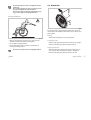
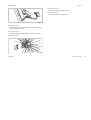
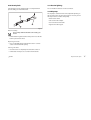
User manual english Table of contents 1 General ................................................................................3 1.1 1.2 1.3 1.4 1.5 Introduction .................................................................................. 3 Warning and instruction signs...............................................3 Description of wheelchair........................................................ 3 Use as per specifications ..........................................................3 Before using the wheelchair ...................................................3 2 Using the wheelchair..........................................................4 2.1 Sitting down / getting up ........................................................4 2.2 Driving and steering the wheelchair................................... 4 2.3 Driving over stairs and steps .................................................. 5 2.4 Driving on ramps and slopes..................................................7 2.5 Stability and balance when sitting in the chair ............... 8 2.6 Drum brake.................................................................................... 9 2.7 Parking brakes............................................................................10 4.13 Air pump...................................................................................... 19 5 Service............................................................................... 20 5.1 5.2 5.3 5.4 5.5 5.6 Cleaning....................................................................................... 20 Maintenance .............................................................................. 20 Service life and disposal ........................................................ 22 Detecting and repairing defects ........................................ 23 Technical data............................................................................ 24 Warranty conditions................................................................ 25 6 Adjustments carried out by the authorized dealer .......26 6.1 Adjusting the footrest ............................................................ 26 6.2 Positioning the rear wheel.................................................... 27 6.3 Aligning the front wheel ....................................................... 29 6.4 Adjusting the backrest........................................................... 29 6.5 Adjusting the height of the armrest ................................. 30 6.6 Moving the clothing guard to another position .......... 31 6.7 Moving the tire cover to another position ..................... 31 3 Transporting the wheelchair .......................................... 12 3.1 Folding and unfolding the wheelchair .............................12 3.2 Removing and installing the rear wheels ........................13 4 Adjustments and options................................................ 14 4.1 4.2 4.3 4.4 4.5 4.6 4.7 4.8 4.9 4.10 4.11 4.12 0 14 Adjusting the parking brakes...............................................14 Adjusting the tension of the backrest cover ..................14 Height adjustable push handles .........................................15 Armrest .........................................................................................15 Fixing strap ..................................................................................16 Transit wheels.............................................................................16 Antitipper.....................................................................................17 Tipper aid .....................................................................................18 Cane holder.................................................................................18 Security belt ................................................................................19 Passive lighting ..........................................................................19 1 Rear wheel Seat Front frame Footplate Front wheel Adapter plate Lateral support Push handles Backrest Figure 1 2 0 1 General 1.3 Description of wheelchair 1.1 Introduction Thank you for purchasing a 0 wheelchair. With the 0Champion you have purchased a topquality product. In order to make optimum use of its functionalities and learn about its safety requirements, please read these operating instructions carefully and follow the safety instructions. 1.2 Warning and instruction signs The following signs and abbreviations are used in these operating instructions: Warning sign containing important information to prevent injuries and material damage. Useful information for user The wheelchair consists of a frame (lateral support and front frame ) to which the seat and the backrest are fixed. A folding mechanism connects the left and right lateral supports and allows folding of the wheelchair. The two rear wheels are connected to the lateral support via an adapter plate . The front wheels and the footrest are fixed to the front frame. (See Figure 1) 1.4 Use as per specifications The wheelchair is driven manually and is used for independent or guided locomotion of gait-impaired persons (e.g. hemiplegia, paraplegia, tetraplegia, multiple sclerosis, traumatic brain injury, etc.). The wheelchair may only be used without a guide by persons who are physically competent to handle the wheelchair (eg. driving, steering and braking). The wheelchair is designed for in- and outdoor use on level ground and paved terrain. 1.5 Before using the wheelchair Required tool: Hexagon socket wrench 3mm Required tool: Wrench 8mm Required tool: Screw driver Some drawings in this manual are allegorized. Your wheelchair model may differ from the pictured one. 0 Before using the wheelchair for the first time, please read Chapter 2 - Using the wheelchair carefully and follow the safety instructions. For security reasons it is essential that you check the functionality of your wheelchair daily. Pay special attention on the following parts: Wheels, backrest, antitipper, pushhandles, quick release fork. Normally, your authorized dealer will unpack and unfold the wheelchair if necessary for you. If you receive your wheelchair unfolded, please read Chapter 3.1 - Folding and unfolding the wheelchair. Using the wheelchair 3 2 Using the wheelchair 2.2 Driving and steering the wheelchair Finding the tipping point Always adjust the clothes you wear and your driving behaviour to the conditions (weather, road conditions, individual skills etc.). Please note that the risk of sliding is higher if the ground is wet, on gravel roads and on rough ground. The tipping point of the wheelchair depends on the adjustment of the seat position. The correct seat position is adjusted depending on parameters such as the weight of the user, the type of handicap and the driver's driving skills. The seat position which is adjusted upon delivery corresponds to the information indicated in your order. 2.1 Sitting down / getting up When getting in or out of the wheelchair, do not stand on the footrests. Danger of tipping! You should only get on/off the wheelchair if you are physically competant. Please consult your physician or therapist. Do not sit on the clothing guard, the tire cover or the armrest when getting on/off the wheelchair. They might bend or break. Danger of injury! The method you use to transfer in and out of your wheelchair will depend on your own capabilities. Generally, the procedure is as follows: Pull the parking brake Hold on to the wheelchair and, if necessary, to a stable object nearby. 4 Using the wheelchair Figure 2 To find the tipping point of your wheelchair, proceed as follows (see Figure 2): When determining the tipping point, an aide must always stand directly behind the wheelchair in order to catch it in case it tips. To ensure that you are in control of your wheelchair at any given point, you should not exceed a speed of 7km/h. (4Mph) 0 With an aide Loosen the brakes Sitting in the wheelchair, move forwards briefly, hold both hand rims tightly and pull back with a slight swing. By shifting your weight slightly and applying a counter-force to the hand rims, the tipping point can be determined. To avoid the wheelchair tipping backward, we recommend that the wheelchair should be equipped with an antitipper (see Chapter 4). Please note that a heavy backpack fixed to the backrest can affect the tipping behaviour of the wheelchair. 2.3 Driving over stairs and steps Always be very careful and move slowly when driving over curbstones, stairs or other steps. Do not try to drive over steps which have a height of more than 25 cm. Only drive on stairs with more than one step if an aide is behind the wheelchair. Figure 3 Driving down a step Drive to the edge of the step, make sure that the wheelchair is in a straight position. Hold on to the two push handles, on the rear of the wheelchair, put one foot to the bottom part of the frame and tilt the wheelchair backward so that the front wheels leave the ground. Hold the wheelchair in this position and push it down the step slowly. The wheelchair driver can support you by using the hand rims. 0 Using the wheelchair 5 Tilt the wheelchair forward until the front wheels have ground contact again. Driving up a step Move the wheelchair backward until the rear wheels hit the edge of the step. Pull back both push handles, tilt the wheelchair until the front wheels leave the ground and pull the rear wheels over the edge. Move the wheelchair until you can safely tilt the wheelchair forward. Without an aide If you want to drive down a step without a guide, you must have perfect control over your wheelchair and must be able to balance it on the rear wheels. (see Finding the Tipping Point in Chapter2.2). Figure 4 Driving down a step Drive to the edge of the step, make sure that the wheelchair is in a straight position. Lift up the front wheels from the floor by shifting your body weight and keep your balance. Now let the two rear wheels roll down over the edge. Make sure to hold the hand rims tightly. Tilt forward the wheelchair until the front wheels have ground contact again. Driving up a step Drive the wheelchair backward until the rear wheels hit the edge of the step. 6 Using the wheelchair 0 Lift up the front wheels from the floor by shifting your body weight and keep your balance. Now let the two rear wheels roll up over the edge. Make sure to hold the hand rims tight. Move the wheelchair until you can tilt the wheelchair forward safely. Lower the front wheels again. 2.4 Driving on ramps and slopes Only drive on long slopes if a guide is behind the wheelchair. Do not drive on steep or lateral slopes (max. assending grade 7°). Danger of tipping! Avoid abrupt changes of direction when driving on slopes. Danger of tipping! Never pull the parking brakes when the wheelchair is in motion. Danger of tipping! Figure 5 Lean forward and drive the wheelchair by pushing the hand rims quickly and powerfully. Downhill When driving downhill direction and, above all, speed must be controlled. Driving uphill To drive uphill you must set the wheelchair in motion and maintain the motion in order to be able to control the direction. 0 Using the wheelchair 7 2.5 Stability and balance when sitting in the chair For many every day life activities you will have to bend out of the wheelchair, forwards, to the side or backwards. This has a great influence on the stability of the wheelchair. In order to keep your balance at any time, please observe the following: Leaning forward Figure 6 Lean back and let the hand rims slip through your hands carefully. You should be able to stop the wheelchair at any time by holding the hand rims. Please note that, the hand rims can heat if you brake for longer periods of time by hand. This applies especially to MaxGrepp and Supergripp handrims Figure 7 Align the front wheels to the front. (To do this, move the wheelchair slightly forward and then back again.) Apply both parking brakes. When leaning forward, make sure that your abdomen remains above the front wheels. 8 Using the wheelchair 0 Do not lean forward too much. You might fall out of the wheelchair! Do not slide forward in your seat to reach out for remote objects. You might fall out of the wheelchair! Do not try to bend your abdomen forward between your legs in order to pick up something from the floor. 2.6 Drum brake Leaning backward Figure 9 If your wheelchair is equipped with a drum brake, a guide can decelerate the wheelchair. The drum brake can also be used as a parking brake. Braking Figure 8 Align the front wheels to the front. (To do this, move the wheelchair forward a bit and then back again.) Do not apply the parking brakes. Reach out backward only as much as possible without leaving your sitting position. Do not lean over the backrest. You might tip backward. Pull back the braking lever at the push-handle. Locking the brake Pull the braking lever firmly until the securing lever engages Release the braking lever. Now, the brake is locked. Releasing the brake Pull the braking lever and push the small securing lever on the underside of the braking lever until it is disengaged Release the braking lever. Now, the brake is released. 0 Using the wheelchair 9 Releasing the brake 2.7 Parking brakes If your wheelchair is not equipped with a drum brake, deceleration is effected manually by applying force on the hand rims of the rear wheels. The parking brakes are used only for keeping the wheelchair in place when standing and to prevent it from rolling away. The correct function of the parking brakes is ensured only if sufficient air is in the tire. (see Chapter 5.2 Maintenance) Pull the braking lever back. Performance brake Never apply the parking brakes when the wheelchair is in motion - Danger of tipping! For adjusting the parking brakes please see chapter 4. Figure 11 Applying the brake Standard brake Push the brake lever forward until it reaches the stopper. Releasing the brake Pull the braking lever back. Figure 10 Applying the brake Push the brake lever forward until it reaches the stopper. 10 Using the wheelchair 0 Figure 13 Active brake Applying the brake Fold the red lever at the hub forward. Releasing the brake Fold the red lever at the hub back. Figure 12 Applying the brake Pull the braking lever forward (beside or between your legs) until it reaches the stopper. Releasing the brake Push the braking lever back (beside or between your legs). Stoplock brake 0 Using the wheelchair 11 3 Transporting the wheelchair Unfolding the wheelchair Your wheelchair is not suitable for use in vehicles. Do not sit on the wheelchair during a transport, use a properly secured seat. 3.1 Folding and unfolding the wheelchair Folding the wheelchair Figure 15 Pull the cord on the front under the seat cover until the ratchet engages completely (1a.) or push forward the shears until the ratchet engages completely by pressing the palm or the back of your hand against the projecting part of the shears (1b.) Pull up the backrest at the push-handles until the ratchet bolts engage in the lateral supports (2.) Figure 14 Remove the seat cushion Pull the pull-strap on the back of the wheelchair up and back (1.). The shears of the folding mechanism under the seat folds up, the backrest folds forward. With both hands, pull the seat cover and the backrest cover upwards (2.). The wheelchair folds up completely. 12 Transporting the wheelchair 0 3.2 Removing and installing the rear wheels To reduce the size of your wheelchair, you can remove the rear wheels. Installing the rear wheels Release the brakes. With one hand, hold the wheelchair in an upright position. With the other hand, hold the wheel at the spokes around the wheel hub (see Figure 1). Press the axle knob with your thumb, keep it pressed. Now insert the axle in the adapter sleeve until it comes to a rest. of the axle tube Release the axle knob. Now, the wheel fits tightly. After installing a wheel, always make sure that the removable axles are engaged completely. The head must be extended completely. Check by pulling the wheels outwards. Figure 1 Removing the rear wheels Release the brakes. With one hand, hold the wheelchair in an upright position. With the other hand, hold the wheel at the spokes around the wheel hub (see Figure 1). Press the axle knob with your thumb and pull the wheel out of the adapter sleeve . 0 Transporting the wheelchair 13 4 Adjustments and options Tighten the hexagon socket bolt at the brake holder again. The function of the parking brakes is only ensured if sufficient air is in the tyre. (see Chapter 5.2 - Maintenance) Ensure that when making any adjustments between the rear wheel and the clothing guard that there is sufficient room to avoid contusions/finger traps. 4.2 Adjusting the tension of the backrest cover 4.1 Adjusting the parking brakes The parking brakes must be readjusted after adjusting the position of the rear wheels. If your wheelchair is equipped with a backrest cover with adjustable tension, you can adjust the tension of the backrest cover to your individual requirements. Figure 17 Figure 16 Make sure that sufficient air is in the tyres. (see Chapter 5.2 Maintenance). Loosen the hexagon socket bolt at the brake holder (hex. socket wrench 5mm), and move the brake to the required position. With the brake applied, the brake shoe should not sink into the tyre more than 4 mm. 14 Adjustments and options Remove the backrest cushion. Loosen the Velcro® straps on the rear side of the seat cover by simply pulling them off. Tighten or loosen the straps, as required, and fix them again. Do not tighten the topmost strap too much, otherwise folding the wheelchair becomes difficult. 0 4.4 Armrest Adjusting the backrest, see Chapter 6 4.3 Height adjustable push handles The stepless height adjustable push handles allow pushing the wheelchair in a comfortable position. To ensure a maximum shoulder room for the wheelchair driver, the push handles are inclined backward. Figure 19 You can swing the armrest away or remove it completely: Lift up the armrest slightly (on rear side) and swing it aside or pull it out completely. Figure 18 Adjusting the height of the push-handles: Loosen the locking bolt Move the handle to the required position Tighten the locking bolt again. 0 Adjustments and options 15 4.5 Fixing strap 4.6 Transit wheels If your wheelchair is too wide for certain applications (e.g. when travelling by train or airplane, or when driving in narrow aisles or through narrow doors), you can use the transit wheels. Figure 20 The fixing strap is used for fixing the wheelchair when folded. This way the wheelchair is unable to unfold unintentionally during transportation, for example. Wrap the fixing strap around the frame and fix it using the Velcro lock. You can use the loop of the fixing strap for carrying the wheelchair. Before unfolding the wheelchair, loosen the fixing strap again and fix it at the seat. 16 Adjustments and options Figure 21 Change-over to transit wheels Move the transit wheels to their working position, by pushing the pin inward until you can pull down the tube. Push in the second pin, too, and pull the tube further down until the pin engages in the recess. Check if the transit wheels are adjusted to the correct height. The distance to the floor must not exceed 2 cm. Move the wheelchair to an object which gives you a firm hold 0 Hold on to the object with one hand and incline the wheelchair until the rear wheel on the opposite side leaves the floor Push your thumb on the head of the removable axle and pull the rear wheel out of the adapter sleeve. 4.7 Antitipper The Antitipper device prevents the wheel chair from tipping backward. Lower the wheelchair again. Now it rests on the transit wheels on one side. Repeat the procedure for the other side. Warning: Now, the parking brakes are no longer effective! Change-over from transit wheels to rear wheels Move the wheelchair to an object which gives you a firm hold Hold on to the object with one hand and incline the wheelchair until the transit wheel on the opposite side leaves the floor Reinstall the rear wheel with the removable axle (also refer to Chapter 3.2 - Installing the rear wheels) After installing the wheels, always make sure that the removable axles are engaged completely. Figure 22 Activating the Antitipper With your foot, press the Antitipper shackle downward and outside at the same time until it engages. In any case deactivate the Antitipper device before driving over a curbstone or a step. Danger of tipping! Deactivating the Antitipper Slightly press the Antitipper shackle down and inside. The device will swing away upward. 0 Adjustments and options 17 4.8 Tipper aid 4.9 Cane holder The tipper aid facilitates tipping the wheelchair for the guide when crossing a step, for example. Figure 23 Hold the wheelchair by the push-handles With one foot, step on the tipper aid and hold the wheelchair tipped until you have passed the obstacle. The tipper aid must not project backward over the outer diameter of the rear wheel. Danger of tipping! 18 Adjustments and options Figure 24 Put the cane in the holder Secure the cane at the push handle using the Velcro strap. The cane must not project backward over the outer diameter of the rear wheel. Danger of tipping! 0 4.10 Security belt 4.11 Passive lighting Your wheelchair can be equipped with a security belt which prevents falling out of the wheelchair. You can install two reflectors on the rear wheels. 4.12 Air pump The air pump is delivered with a valve adapter. Depending on the size of the valve of your model, it may be necessary to turn the adapter at the air outlet of the pump. Remove the locknut Take out the valve adapter Turn it around and reinstall it Tighten the locknut again. Figure 25 Belt assembly The assembly of the belt should be carried out by your dealer! Pull the belt through the backrest and position it so that the buckle is placed at the front. Opening the belt Press on the PRESS button and pull the locker socket . The buckle will open up. out of its Closing the belt Insert the locker Pull the belt 0 completely into the buckle socket . until you are secured in the wheelchair. Adjustments and options 19 5 Service Maintenance plan Weekly Check the proper fitting of the rear wheel axle in the sleeve 5.1 Cleaning The service life of your wheelchair increases if you maintain and clean it regularly. Check air pressure in tyres Monthly Check bolted connections Oil removable axles Clean cushions and metal parts with a moist, soft cloth. Carefully dry your wheelchair after using it in rainy weather. Check tension of spokes Yearly General check by an authorized dealer Sand and sea water may damage the ball bearings. Measuring the air pressure After using your wheelchair in a dirty environment, clean and dry it thoroughly as soon as possible. Do not use rough scouring agents, aggressive cleaning agents or high-pressure cleaning machines. To ensure that the driving and braking function is maintained, it is important that the air pressure in the tires is correct. Check weekly, if there is sufficient air in the tires. The optimum pressure values are indicated in the following table: 5.2 Maintenance Type of tire Air pressure We strongly advise that you should have your wheelchair thoroughly checked by the authorized dealer once a year, as a minimum. This is in addition to to the general maintenance procedures detailed below. Smooth-running tires 7 bars 700 kPa Treaded tires 7.5 bars 750 kPa 110 psi Indoor sports tire (Collé) 10 bars 1000 kPa 140 psi Mountain bike tire 5 bars 500 kPa 70 psi In order to make sure that your wheelchair will give you the necessary safety and reliability over its whole service life, you should carry out the following work regularly, or have it carried out by your authorized dealer. 100 psi If you are not sure about the tires of your wheelchair, contact your authorized dealer. 20 0textunit UM05_en_Champion.doc Oiling the removable axles To ensure the proper function of the removable axles, they must be oiled at regular intervals. Pour some resin-free bicycle oil on a cloth and slightly oil the balls at the end of the removable axles, the axle and the push-button. Checking the bolted connections Bolted connections may loosen if the wheelchair is used frequently. Check the bolts monthly for tight fit, re-tighten, if necessary. Locknuts and locking bolts should be replaced if they become loose. For replacement please contact an authorized dealer. Fitting tires Inflate the tube slightly until it has its round shape. Insert the valve in the valve hole of the wheel rim and insert the tube in the tire (the tube should be inside the tire completely without folds). Starting at the valve push the tire flanks over the edge of the wheel rim with both hands. Make sure that the tube is not jammed between the tire and the wheel rim. Use a bicycle tire lever for this. Do not use sharp or pointed objects such as screw drivers in order to prevent the inner tube from being damaged. Pump the tire up to the maximum operating pressure. Make sure that the tire does not loose air anymore. Spiderwheels Repairing or replacing tires Take off the wheel (see Chapter 3.2). Remove the wheel. Deflate the tire by pressing on the valve. Tighten the bolt in the wheelrim. Lift one flank of the tire off the wheel rim. Use a bicycle tire lever for this. Do not use sharp or pointed objects such as screw drivers in order to prevent the inner tube from being damaged. Pull the tube out of the tire. Repair the tube using a bicycle tire repair kit. If repairing is not possible, replace the tube. 21 If the Spiderwheel starts squeeking then proceed as follows: Last update: 02.11.06 Spare parts All spare parts are available at your authorized dealer. To determine the size of a front wheel compare its outer diameter to the scale on the back of this manual. 5.3 Service life and disposal We assume that our wheelchairs will be in use daily. For this reason the whole equipment is subjected to an almost continuous stress and, consequently, a natural wear and tear. Taking this into consideration and provided that the wheelchair ® is maintained properly, the lifetime of the Küschall wheelchairs is approximately 5 years. If the wheelchair is used less frequently, e.g. if you use it inside your apartment only, and if it is maintained perfectly, the service life will increase accordingly. For proper disposal of your wheelchair, please contact your authorized dealer. 22 0textunit UM05_en_Champion.doc 5.4 Detecting and repairing defects The daily use of the wheelchair, new adjustments or changed requirements may result in defects which can be repaired. We recommend that the adjustments should be carried out by your authorized dealer. Defect Possible cause Remedy Wheelchair does not roll straight Wrong air pressure in one of the rear wheels Correct air pressure (Chapter 5.2) Bearing block of the front wheel fork is not in a vertical position Put bearing block in vertical position (Chapter 6.4) The rear wheels do not run parallel or are axially shifted Correct the shear pretension or the track (Chapter 6.1) Front wheels not adjusted to same height Position the front wheels such that they touch the floor at the same time (Chapter 6.4) One or more spokes are broken replace defective spoke(s) Spokes are not equally tightened Tighten the loose-fitting spokes Front wheel bearings dirty or damaged Clean or replace bearing Wheelchair tips too easily Rear wheel mounted too far to the front Shift wheels backward (Chapter 6.3) Seat angle too large Mount adapter place at a lower position of the lateral support (Chapter 6.3) Backrest angle too large Reduce backrest angle (Chapter 6.5) Poor or asymmetric brake grip Wrong air pressure in one or both rear wheels Correct air pressure (Chapter 5.2) Rolling resistance is very high Rear wheels are off track Change track (Chapter 6.1) Select smaller front fork Wrong air pressure in the rear wheels Correct air pressure (Chapter 5.2) Front wheels vibrate when driving fast Tension at front wheel bearing block too low Tighten nut at bearing block axle slightly Unfolding the wheelchair is difficult Folding mechanism adjusted too hard Adjust folding mechanism (Chapter 6.1) Back cover tightened too much Slightly loosen topmost strap 0 Service 23 5.5 Technical data Frame 75° short Total length SB Seat width [cm] 54–64 RL W [cm] 85–93.5 [cm] 34–44 45–55 42.5–51.5 45–55 SHh Height of seat rear 36–50 36–47 36–49 40–50 32–40 40–50 [cm] 37–47 SW Seat angle [cm] 2–10 (6) ST Seat depth [cm] 40 / 45 UL Length of lower leg [cm] 33–40 RH Backrest height RL W Backrest angle UL SHv Height of seat front [cm] 41.5–51.5 SW GL 2) ST SHv 1) EW long RH Total width Frame 90° short SHh GB long [cm] 31.5–48 (37.5) 74°–92° (87.5°) GL Weight 3) Maximum load [kg] 11.6 [kg] 120 SB Bold figures: standard value GB = SB + 20 cm depends on seat angle, length of lower leg, rear wheel and position of footrest 3) With standard configuration, can vary +/– 1) 2) GB Figure 26 24 Service 0 0textunit UM05_en_Champion.doc 5.6 Warranty conditions Standard terms This is to certify that your 0wheelchair is warranted by Küschall®, for an unlimited period of time for the frame and 24 month for all other parts. This warranty is subject to the following conditions: ® 1. Only küschall wheelchairs purchased at full price are warranted against defective workmanship and materials. 2. If a defect or fault is discovered the Küschall® dealer from whom the appliance was purchased should be notified immediately. 3. The manufacturer will not accept responsibility for damage caused by misuse or the non-observance of the instructions set out in the user manual. 4. During the period of warranty, any parts that have become defective due to faulty workmanship or materials, will be renewed or repaired free of charge by the Küschall® dealer. 5. The warranty will be forfeited should any unauthorised alteration be made to the equipment. 6. The purchaser’s statutory rights under the consumer Protection Act are not affected. 7. If the purchaser mounts additional adaptions to their Küschall®-wheelchair, they must obtain a written authorization from Küschall AG. Otherwise any possible liability claims cannot be asserted. 0 Limitation of liability This warranty does not extend to the consequential costs resulting from fault clearance, in particular freight and travel costs, loss of earnings, expenses, etc. Küschall® shall not be liable for: natural wear and tear inappropriate and incorrect use defective assembly or setting up the purchaser or third parties defective or neglectful treatment use of unsuitable spares. Service 25 6 Adjustments carried out by the authorized dealer 6.1 Adjusting the footrest Adjusting the height The height of the footrest can be adjusted in steps of 12mm. This chapter is expressly intended for trained authorized dealers. Authorized dealers should inspect the wheelchair thoroughly for wear or damage and replace components as necessary Minor changes may have great effects on the seat position and the driving behaviour and thus the safety. Since many adjustments influence each other, sufficient product know-how and technical experience is required in order to carry out these adjustments properly. We recommend that you have all adjustments and repair work described in this section carried out by an authorized Küschall® dealer. Figure 27 Loosen the bolt For your local authorized dealer, please contact the küschall® representation in your country (see back of this user manual). above the footrest in the frame tube Extend the foot part telescope to the required length and insert the bolts in the holes which are closest Tighten the locking bolt again firmly. Adjusting the angle The angle between the footrest and the frame tube can be adjusted continuously. 26 Adjustments carried out by the authorized dealer 0 0textunit UM05_en_Champion.doc Figure 28 Figure 29 Slightly loosen the bolted connection below the foot plate which fixes the telescopic tube in the foot plate fixture. Disassemble the telescopic tubes from the footplate using the bolts Adjust the angle as required Loosen the bolts Tighten the bolts again. Turn the footplate supports as shown in the drawing above and mount them again. Adjusting the position The footrest can be mounted in 2 positions. To change the position of the footrest, proceed as follows: to remove the footplate supports 6.2 Positioning the rear wheel The rear wheel can be mounted to the adapter plate in 4 different positions (horizontal). The adapter plate can be mounted to the lateral support in 5 different positions (vertical). These adjustments have an influence on the floor-seat distance and the seat angle and therefore the stability of the wheelchair. Vertical adjustment If the adapter plate is mounted in a higher position at the lateral support, the floor-seat distance decreases and the seat angle increases (lower stability) if the front wheel adjustment is not changed 0 Adjustments carried out by the authorized dealer 27 If the adapter plate is mounted in a lower position at the lateral support, the floor-seat distance increases and the seat angle decreases (higher stability) Horizontal adjustment Figure 31 Figure 30 The further back you mount the adapter sleeve in the adapter plate, the higher the tipping safety of the wheelchair is. Loosen the 4 bolts of the adapter plate Loosen the adapter sleeve in the adapter plate Adjust the adapter plate to the required height Insert the adapter sleeve in the required hole of the adapter plate Tighten the bolts again firmly. Tighten the adapter sleeve again firmly (Torque: 70Nm) Make sure to make the same adjustment on both sides of the wheelchair. 28 Adjustments carried out by the authorized dealer Make sure to make the same adjustment on both sides of the wheelchair 0 0textunit UM05_en_Champion.doc 6.3 Aligning the front wheel 6.4 Adjusting the backrest After adjustments which influence the seat height or the seat angle, the axis of the bearing block must be aligned vertically to the floor again. Adjusting the height The height of the standard backrest with push-handle can be adjusted in steps of 15 mm. Figure 33 Figure 32 Push up the backrest cushion until the bolt is visible Loosen the bolts at the bearing block Loosen the bolt and move the backrest to the required height Insert the upper excenter into the required position (further at front or rear side, depending on the seat angle) Insert the bolt in the hole which is closest and tighten it again. Turn the lower excenter (with bolt inserted) until the axis of the bearing block is aligned vertically to the floor Tighten both bolts again. 0 Adjustments carried out by the authorized dealer 29 Adjusting the backrest angle 6.5 Adjusting the height of the armrest The further the backrest is inclined backward, the lower the tipping stability of the wheel chair. Figure 35 Take off the armrest Figure 34 Loosen and take out the bolts at the arm rest tube Allow the backrest to engage in the lateral support Move the threaded sleeve in the inside of the tube to the required hole Remove the lower bolt lateral support Insert the tube again and tighten it. of the ratchet bolt fixture at the Move the backrest to the required position Insert the armrest again by letting it engage in the supporting sleeve. Insert the bolt in the hole which is closest and tighten it again Repeat the procedure on the other side of the wheel chair. Make sure to make the same adjustment on both sides of the wheel chair. 30 Adjustments carried out by the authorized dealer 0 0textunit UM05_en_Champion.doc 6.6 Moving the clothing guard to another position 6.7 Moving the tire cover to another position Figure 37 Figure 36 The clothing guard is bolted to the lateral support at the front and to the wheel support at the back. You can move it to another position or remove it. Loosen the bolt and loosen the bolt can move the clothing guard slightly until you Turn the clothing guard until it covers the tire completely The tire cover is bolted to a support plate. You can move it to another position or replace it: Loosen both bolts Take off the clothing guard and mount it to the holes which are closest, so that the clothing guard covers the tire completely. Fix the clothing guard in the hole which is closest using the bolt and tighten the bolt again. 0 Adjustments carried out by the authorized dealer 31 Your authorized dealer: Küschall AG Benkenstrasse 260 CH-4108 Witterswil küschall® distributors UM_Champion EN | 1485348 | 10/2006 Belgium & Luxemburg: Invacare · Autobaan 14 · B-8210 Loppem Danmark: Invacare A/S · Sdr. Ringvej 39 · DK-2605 Brøndby Deutschland & Ost Europa: Invacare Deutschland GmbH · Kleiststraße 49 • D-32457 Porta Westfalica Eire: Invacare Ltd. ·�� Unit �������� 5, Seatown ������������������������������������������������� Business Campus�������������������������� ·������������������������� Seatown ����������������������� Road����������� ·���������� Swords, �������� Co. ������������� ·�������� Dublin ������ España: Invacare S.A. · c/ Areny · s/n Polígon Industrial de Celrà · E-17460 Celrà (Girona) France: Invacare Poirier SAS · Route de St Roch · F-37230 Fondettes Italia: Invacare Mecc San s.r.l. · Via dei Pini 62 · I-36016 Thiene (VI) Nederland: Invacare B.V. · Celsiusstraat 46 · NL-6716 BZ Ede Norge: Invacare AS · Grensesvingen 9 · N-0603 Oslo Portugal: Invacare (Portugal), Lda · Rua Senhora de Campanhã 105 · P-4369-001 Porto Schweiz, Österreich & Middle East: Küschall AG · Benkenstrasse 260 · CH-4108 Witterswil Sverige & Suomi: Invacare AB · Fagerstagatan 9 · P.O. Box 66 · S-163 91 Spånga United Kingdom: Invacare Ltd. · South Road · Bridgend Industrial Estate · Bridgend CF31 3PY · UK www.kuschall.com The küschall® brand is a registered trademark. Every effort has been made to ensure that the contents of this publication are fully up-to-date at the time of going to print. As part of its ongoing improvement of products, Küschall AG reserves the right to modify existing models at any time. küschall® dealers will be notified of any such modifications. Any use of this publication, of of parts thereof, as well as any reproduction of images, must have the written consent of Küschall AG. 3’’ 4’’ 5’’ 6’’


![日本語 [Rev 1.00] - ViTiny マイクロスコープ](http://vs1.manualzilla.com/store/data/006555709_3-84b0277bd17a0b700047e713a429bb8f-150x150.png)