1
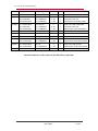
IEC 101-104-103 interoperability list
Budapest, 27. 05. 2011.
IEC 101-104-103 interoperability list
CONTENTS
1
2
IEC 60870-5-101 (Edition 2) and IEC 60870-5-104:2000 interoperability list ....................3
1.1
System or device ..........................................................................................................3
1.2
Network configuration (IEC 60870-5-101 only) ............................................................3
1.3
Physical layer (IEC 60870-5-101 only) ........................................................................3
1.4
Link layer (IEC 60870-5-101 only) ...............................................................................4
1.5
Application layer ...........................................................................................................5
1.6
Selection of standard ASDU's ......................................................................................6
1.7
Basic application functions ...........................................................................................8
IEC 60870-5-103 interoperability list ................................................................................ 12
2.1
Physical layer ............................................................................................................ 12
2.2
Link layer ................................................................................................................... 12
2.3
Aplication layer .......................................................................................................... 12
2.4
Selection of standard information numbers in monitor direction ............................... 13
2.5
Selection of standard information numbers in control direction ................................ 18
2011/05/27
2/19
IEC 101-104-103 interoperability list
1 IEC 60870-5-101 (Edition 2) and
IEC 60870-5-104:2000 interoperability list
1.1 System or device
☐ System definition
☐ Controlling station definition (master)
☑ Controlled station definition (slave)
1.2 Network configuration (IEC 60870-5-101 only)
☑ Point-to-point
☐ Multiple point-to-point
☐ Multipoint-partyline
☑ Multipoint-star
1.3 Physical layer (IEC 60870-5-101 only)
Transmission speed
☐ 100 bit/s
☐ 300 bit/s
☑ 1200 bit/s
☑ 4800 bit/s
☑ 19200 bit/s
☐ 56000 bit/s
☐ 200 bit/s
☐ 600 bit/s
☑ 2400 bit/s
☑ 9600 bit/s
☑ 38400 bit/s
☐ 64000 bit/s
Note: The transmission speed is equal in the control and the monitor direction.
Supported media is RS-485, HFBR type 1 mm plastic fiber optic and
unmodulated multimode glass fiber with ST type connector. Please note: all
kind of serial connectors are ordering option!
2011/05/27
3/19
IEC 101-104-103 interoperability list
1.4 Link layer (IEC 60870-5-101 only)
Link transmission procedure:
☐ Balanced transmission
☑ Unbalanced transmission
Address field of the link
☐ Not present
☑ One octet
☑ Two octets
☐ Structured
☐ Unstructured
Frame length
Maximum length of the frame in control direction: Not limited
Maximum length of the frame in monitor direction: General parameter in EuroCAP
tool
ASDU class 2 assignment
Type identification
Cause of transmission
<1> M_SP_NA_1
<3> M_DP_NA_1
<13> M_ME_NC_1
<15> M_IT_NA_1
<2> Background scan
Note: ASDU class 2 data sent only if background scan enabled generally and at least
one object has background scan property set.
2011/05/27
4/19
IEC 101-104-103 interoperability list
1.5 Application layer
Common address of ASDU
☑ One octet
☑ Two octets
Note: The common address of ASDU is always the same as the link address.
In IEC 60870-5-101 the length of the common address can be set by EuroCAP
tool
In IEC 60870-5-104 the length of the common address is always two octets
Information object address
☑ One octet
☑ Two octets
☑ Three octets
☐ Structured
☐ Unstructured
Note: In IEC 60870-5-101 the length of the information object address can be set by
EuroCAP tool
In IEC 60870-5-104 the length of the information object address is always three
octets
Cause of transmission
☑ One octet
☑ Two octets (with originator)
Note: In IEC 60870-5-101 the length of the COT can be set by EuroCAP tool
In IEC 60870-5-104 the length of the COT is always two octets
2011/05/27
5/19
IEC 101-104-103 interoperability list
1.6 Selection of standard ASDU's
Process information in monitor direction
☑ <1> Single-point information
☐ <2> Single-point information with time tag
☑ <3> Double-point information
☐ <4> Double-point information with time tag
☐ <5> Step-position information
☐ <6> Step-position information with time tag
☐ <7> Bitstring of 32 bit
☐ <8> Bitstring of 32 bit with time tag
☐ <9> Measured value, normalized value
☐ <10> Measured value, normalized value with time tag
☐ <11> Measured value, scaled value
☐ <12> Measured value, scaled value with time tag
☑ <13> Measured value, short floating point value
☐ <14> Measured value, short floating point value with time tag
☑ <15> Integrated total
☐ <16> Integrated total with time tag
☐ <17> Event of protection equipment with time tag
☐ <18> Packed start events of protection with time tag
☐ <19> Packed output circuit information of protection with time tag
☐ <20> Packed single-point information with status change detection
☐ <21> Measured value, normalized value without quality descriptor
☑ <30> Single-point information with time tag Cp56Time2a
☑ <31> Double-point information with time tag Cp56Time2a
☐ <32> Step position information with time tag Cp56Time2a
☐ <33> Bitstring of 32 bit with time tag Cp56Time2a
☐ <34> Measured value, normalized value with time tag Cp56Time2a
☐ <35> Measured value, scaled value with time tag Cp56Time2a
☑ <36> Measured value, short floating point value with time tag Cp56Time2a
☑ <37> Integrated total with time tag Cp56Time2a
☐ <38> Event of protection equipment with time tag Cp56Time2a
☐ <39> Packed start events of protection with time tag Cp56Time2a
☐ <40> Packed output circuit information of protection with time tag Cp56Time2a
2011/05/27
6/19
IEC 101-104-103 interoperability list
Process information in control direction
☑ <45> Single command
☑ <46> Double command
☑ <47> Regulating step command
☐ <48> Set point command, normalized value
☐ <49> Set point command, scaled value
☐ <50> Set point command, short float value
☐ <51> Bitstring of 32 bit
☑ <58> Single command with time tag Cp56Time2a
☑ <59> Double command with time tag Cp56Time2a
☑ <60> Regulating step command with time tag Cp56Time2a
System information in monitor direction
☑ <70> End of initialization
System information in control direction
☑ <100> Interrogation command
☐ <101> Counter interrogation command
☐ <102> Read command
☑ <103> Clock synchronization command
☐ <104> Test command
☐ <105> Reset process command
☐ <106> Delay acquisition command
Parameter in control direction
☐ <110> Parameter of measured value, normalized value
☐ <111> Parameter of measured value, scaled value
☐ <112> Parameter of measured value, short floating point value
☐ <113> Parameter activation
File transfer
☐ <120> File ready
☐ <121> Section ready
☐ <122> Call directory, select file, call section
☐ <123> Last section, last segment
☐ <124> Ack file, section
☐ <125> Segment
☐ <126> Directory
2011/05/27
7/19
IEC 101-104-103 interoperability list
Type identification and cause of transmission assignments
Type identification
<1> M_SP_NA_1
<2> M_DP_NA_1
<13> M_ME_NC_1
<15> M_IT_NA_1
<30> M_SP_TB_1
<31> M_DP_TB_1
<36> M_ME_TF_1
<37> M_IT_TB_1
<45> C_SC_NA_1
<46> C_DC_NA_1
<47> C_RC_NA_1
<59> C_SC_TA_1*
<60> C_DC_TA_1*
<61> C_RC_TA_1*
<70> M_EI_NA_1
COT in monitor direction
<2> background scan
<20> interrogated by general
interrogation
<100> C_IC_NA_1
<7> activation confirmation
<9> deactivation confirmation
<10> activation termination
<7> activation confirmation
<103> C_CS_NA_1
COT in control direction
<3> spontaneous
<7> activation confirmation
<9> deactivation confirmation
<10> activation termination
<6> activation
<8> deactivation
<4> initialized
<6> activation
<8> deactivation
<6> activation
*: These commands are not part of the IEC 60970-5-101 standard, but introduced in
60870-5-104. The EuroProt+ platform devices accept these commands too.
1.7 Basic application functions
Station initialization
☐ Remote initialization
Cyclic data transmission
☐ Cyclic data transmission
Note: Cyclic data transmission not supported but background scan messages used
Read procedure
☐ Read procedure
Spontaneous transmission
☑ Spontaneous transmission
2011/05/27
8/19
IEC 101-104-103 interoperability list
Note: All changes of single and double point information, floating point measurands
and counters causes spontaneous transmission. The generated ASDUs always
contain 7 octet binary time tag (Cp56Time2a). The time stamp is always local
time.
Double transmission of information objects with cause of transmission
spontaneous
☐ Single point information
☐ Double point information
☐ Step position information
☐ Bitstring of 32 bit
☐ Measured value, normalized value
☐ Measured value, scaled value
☐ Measured value, short floating point number
Station interrogation
☑ global
☐ group 1
☐ group 5
☐ group 9
☐ group 13
☐ group 2
☐ group 6
☐ group 10
☐ group 14
☐ group 3
☐ group 7
☐ group 11
☐ group 15
☐ group 4
☐ group 8
☐ group 12
☐ group 16
Clock synchronization
☑ Clock synchronization
☐ Day of week used
☐ RES1, GEN (time tag substituted/not substituted) used
☐ SU-bit (summertime) used
Note: Legacy protocol time synchronization should be enabled to set the system time.
See the system settings using HMI or WEB interface. The sent and received
time is always local time.
2011/05/27
9/19
IEC 101-104-103 interoperability list
Command transmission
☑ Direct command
☐ Direct set point command
☑ Select and execute command
☐ Select and execute set point command
☑ C_SE_ACTTERM used
☐ No additional information
☐ Short pulse duration
☐ Long pulse duration
☐ Persistent output
Transmission of integrated totals
☐ Mode A: local freeze with spontaneous transmission
☐ Mode B: local freeze with counter interrogation
☐ Mode C: freeze and transmit by counter interrogation commands
☐ Mode D: freeze by counter-interrogation command, frozen values reported
spontaneously
☐ Counter read
☐ Counter freeze without reset
☐ Counter freeze with reset
☐ Counter reset
☐ General request counter
☐ Request counter group 1
☐ Request counter group 2
☐ Request counter group 3
☐ Request counter group 4
Parameter loading
☐ Threshold value
☐ Smoothing factor
☐ Low limit for transmission of measured value
☐ High limit for transmission of measured value
Parameter activation
☐ Act/deact persistent cyclic or periodic transmission of the addressed object
2011/05/27
10/19
IEC 101-104-103 interoperability list
Test procedure
☐ Test procedure
File transfer
File transfer in monitor direction
☐ Transparent file
☐ Transmission of disturbance data of protection equipment
☐ Transmission of sequences of events
☐ Transmission of sequences of recorded analogue values
File transfer in control direction
☐ Transparent file
Background scan
☑ Background scan
Note: The background scan should be enabled generally and the BG scan property of
the monitored object should be set. The periodicity of the messages is a general
setting. See EuroCAP tool user manual for the details.
Acquisition of transmission delay
☐ Acquisition of transmission delay
2011/05/27
11/19
IEC 101-104-103 interoperability list
2 IEC 60870-5-103 interoperability list
2.1 Physical layer
Electrical interface
☑ RS-485 (ordering option)
Optical interface
☑ Glass fibre (ordering option)
☑ Plastic fibre (ordering option)
☑ Idle state: light on
☑ Idle state: light off
Note: idle state is defined in the standard as light on (IEC 60870-5-103 first edition,
chapter 5.1) For compatibility reason the idle state can be changed using the
EuroCAP tool.
Transmission speed
☑ 9600 bit/s
☑ 19200 bit/s
Note: transmission speed supported from 1200 to 38400 bit/s. The speed can be set by
local HMI or WEB interface.
2.2 Link layer
There are no choices for the link layer.
2.3 Aplication layer
Common address of ASDU
☑ One common address of ASDU (identical with station address)
☐ More than one common addrss of ASDU
2011/05/27
12/19
IEC 101-104-103 interoperability list
2.4 Selection of standard information numbers in monitor
direction
System functions in monitor direction
☑ <0> End of General Interrogation
☑ <0> Time synchronization
☑ <2> Reset FCB
☑ <3> Reset CU
☐ <4> Start/Restart
☑ <5> Power on
Status indication in monitor direction
☑ <16> Auto-recloser active
☑ <17> Teleprotection active
☑ <18> Protection active
☑ <19> LED reset
☑ <20> Monitor direction blocked
☑ <21> Test mode
☑ <22> Local parameter setting
☑ <23> Characteristic 1
☑ <24> Characteristic 2
☑ <25> Characteristic 3
☑ <26> Characteristic 4
☑ <27> Auxiliary input 1
☑ <28> Auxiliary input 2
☑ <29> Auxiliary input 3
☑ <30> Auxiliary input 4
Note: Not all of these information objects presented in the device.
Any internal boolean or enumerated event channel can be mapped to these
information objects by the user. See the EuroCAP tool user manual for the
details.
2011/05/27
13/19
IEC 101-104-103 interoperability list
Supervision indication in monitor direction
☑ <32> Measured supervision I
☑ <33> Measured supervision U
☑ <35> Phase sequence supervision
☑ <36> Trip circuit supervision
☑ <37> I>> back-up operation
☑ <38> VT fuse failure
☑ <39> Teleprotection disturbed
☑ <46> Group warning
☑ <47> Group alarm
Note: Not all of these information objects presented in the device.
Any internal boolean or enumerated event channel can be mapped to these
information objects by the user. See the EuroCAP tool user manual for the
details.
Earth fault indication in monitor direction
☑ <48> Earth fault L1
☑ <49> Earth fault L2
☑ <50> Earth fault L3
☑ <51> Earth fault forvard i.e. line
☑ <52> Earth fault reverse i.e. busbar
Note: Not all of these information objects presented in the device.
Any internal boolean or enumerated event channel can be mapped to these
information objects by the user. See the EuroCAP tool user manual for the
details.
Fault indication in monitor direction
☑ <64> Start/pick-up L1
☑ <65> Start/pick-up L2
☑ <66> Start/pick-up L3
☑ <67> Start/pick-up N
☑ <68> General trip
☑ <69> Trip L1
☑ <70> Trip L2
☑ <71> Trip L3
☑ <72> Trip I>> (back-up operation)
☑ <73> Fault location X in ohms
☑ <74> Fault forward/line
☑ <75> Fault reverse/busbar
☑ <76> Teleprotection signal transmitted
2011/05/27
14/19
IEC 101-104-103 interoperability list
☑ <77> Teleprotection signal received
☑ <78> Zone 1
☑ <79> Zone 2
☑ <80> Zone 3
☑ <81> Zone 4
☑ <82> Zone 5
☑ <83> Zone 6
☑ <84> General start/pick-up
☑ <85> Breaker failure
☑ <86> Trip measuring system L1
☑ <87> Trip measuring system L2
☑ <88> Trip measuring system L3
☑ <89> Trip measuring system E
☑ <90> Trip I>
☑ <91> Trip I>>
☑ <92> Trip IN>
☑ <93> Trip IN>>
Note: Not all of these information objects presented in the device.
Any internal boolean or enumerated event channel can be mapped to these
information objects by the user. See the EuroCAP tool user manual for the
details.
Auto-reclosure indication in monitor direction
☑ <128> CB on by AR
☑ <129> CB on by long-time AR
☑ <130> AR blocked
Note: Not all of these information objects presented in the device.
Any internal boolean or enumerated event channel can be mapped to these
information objects by the user. See the EuroCAP tool user manual for the
details.
Measurands in monitor direction
☐ <144> Measurand I
☐ <145> Measurand V
☐ <146> Measurand I, V, P, Q
☐ <147> Measurand In, Ven
☐ <148> Measurand I1,2,3, V1,2,3, P, Q, f'
Note: In EuroProt+ platform floating point type data is used to represent measurands.
There is no general way to convert them to MEA value without loss of
information. Generic functions are used to transfer measurands and counters.
2011/05/27
15/19
IEC 101-104-103 interoperability list
Private information in monitor direction
☑ <160-239> Private data, can be mapped any internal data using EuroCAP tool
Note: Any internal boolean or enumerated event channel can be mapped to this
information objects by the user. See the EuroCAP tool user manual for the
details.
Generic functions in monitor direction
☑ <240> Read headings of all defined groups
☑ <241> Read values or attributes of all entries of one groups
☑ <243> Read directory of a single entry
☑ <244> Read value or attribute of a single entry
☑ <245> End of general interrogation of generic data
☐ <249> Write entry with confirmation
☐ <250> Write entry with execution
☐ <251> Write entry aborted
Note: Generic service is used to access the current value of the measurands and the
counter data.
The following group headings are supported:
GIN 0100h: Measurands
GIN 0200h: Counters
All other headings are not existed.
These headings have description field only
Inside the group there are some entries. The number of entries are configuration
dependent.
All measurand type entry has an OS8ASCII type description, an OS8ASCII type unit
definition and a R32.23 float type actual value data.
All counter type entry has an OS8ASCII type description and an UI type actual value
data.
2011/05/27
16/19
IEC 101-104-103 interoperability list
GIN
KOD
Datatype
Datasize
Nr
Value
0100h
<10> Description
<1> OS8ASCII
9
1
“Measurands”
0101h
<1> Actual value
<9> Dimension
<10> Description
<7> R32.23
<1> OS8ASCII
<1> OS8ASCII
4
0—32
1--64
1
1
1
Value of the first measurand
The name of the unit
Internal name of the first meas.
0102h
<1> Actual value
<9> Dimension
<10> Description
<7> R32.23
<1> OS8ASCII
<1> OS8ASCII
4
0--32
1--64
1
1
1
Value of the 2nd measurand
The name of the unit
Internal name of the 2nd meas.
0103h
….....
….....
…...
…..
0200h
<10> Description
<1> OS8ASCII
8
1
“Counters”
0201h
<1> Actual value
<10> Description
<3> UI
<1> OS8ASCII
4
1--64
1
1
Value of the first counter
Internal name of the first counter
0202h
<1> Actual value
<10> Description
<3> UI
<1> OS8ASCII
4
1--64
1
1
Value of the 2nd counter
Internal name of the 2nd counter
0203h
….....
….....
…...
…..
…....
…....
Internal structure of the entries in the EuroProt+ platform
2011/05/27
17/19
IEC 101-104-103 interoperability list
2.5 Selection of standard information numbers in control
direction
System functios in control direction
☑ <0> Initiation of general interrogation
☑ <0> Time synchronization
Note: Legacy protocol time synchronization should be enabled to set the system time.
See the system settings using HMI or WEB interface. The sent and received
time is always local time.
General commands in control direction
☑ <16> Auto-recloser on/off
☑ <17> Teleprotection on/off
☑ <18> Protection on/off
☑ <19> LED reset
☑ <23> Activate characteristic 1
☑ <24> Activate characteristic 2
☑ <25> Activate characteristic 3
☑ <26> Activate characteristic 4
Note: Not all of these commands available in all devices. Any internal control channel
can be mapped to these commands by the user. See EuroCAP tool user manual
for the details.
Private commands in control direction
☑ <32-239> Private command, can be mapped any internal control channel
using EuroCAP tool
Generic functions in control direction
☑ <240> Read headings of all defined groups
☑ <241> Read values or attributes of all entries of one groups
☑ <243> Read directory of a single entry
☑ <244> Read value or attribute of a single entry
☑ <245> General interrogation of generic data
☐ <248> Write entry
☐ <249> Write entry with confirmation
☐ <250> Write entry with execution
☐ <251> Write entry abort
2011/05/27
18/19
IEC 101-104-103 interoperability list
Basic application functions
☐ Test mode
☐ Blocking of monitor direction
☐ Disturbance data
☑ Generic services
☑ Private data
2011/05/27
19/19