1
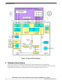
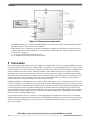
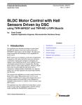
Freescale Semiconductor
Application Note
Document Number: AN4058
Rev. 0, 4/2010
BLDC Motor Control with Hall Effect
Sensors Using the 9S08MP
by:
Eduardo Viramontes
Systems and Applications Engineering
Freescale Technical Support
1 Introduction
This application note describes a brushless DC (BLDC) motor
control system using a predefined hardware reference design. It
explains the hardware concept (not in detail), for further details
about the hardware, look for the user guide titled 3-Phase
BLDC/PMSM Low-Voltage Motor Control Drive (document
LVMCDBLDCPMSMUG) and the user manual titled
MC9S08MP16 Controller Daughter Board for BLDC/PMSM
Motor Control Drive (document LVBLDCMP16DBUM) at
www.freescale.com.
This application uses the MC9S08MP 8-bit microcontroller. The
device has specialized control hardware that allows for reduced
software overhead and higher control efficiency.
BLDC motors are more frequently used over traditional brushed
motors for their increased efficiency and reduced maintenance
needs, mainly through elimination of wearable and
friction-causing brushes. The reduced cost of embedded systems,
plus the features in microcontrollers like the MC9S08MP make
it more convenient to offer motor control systems for BLDC
motors (even with their incremented cost) because of the need
for permanent magnets. The benefits in ease of control usually
outweighs the added cost of BLDC motors. Their speed is
directly proportional to the applied voltage, low maintenance,
and ease of customization of control parameters.
2 System Description
This application consists of three parts:
© 2009 Freescale Semiconductor, Inc.
Contents
1 Introduction...........................................................1
2 System Description...............................................1
2.1 BLDC Basics.................................................2
2.1.1 Three-Phase BLDC Motor....................2
2.1.2 Commutation—Moving the BLDC
Motor.....................................................3
2.1.3 Controlling Speed and Torque...............6
2.2 9S08MP16 Controller Advantages and
Features.........................................................9
2.3 System Block Diagram.................................9
3 Software Description...........................................10
4 Application Setup................................................11
5 Conclusion...........................................................12
System Description
• This document—Describing the application and its usage.
• Application code—Included as an attachment to the application note.
• FreeMaster control page—Also included as an attachment to the application note.
As mentioned before, the hardware used in this application note is covered elsewhere. It is based on a 3-phase BLDC/PMSM
low-voltage motor control drive board module that provides a broad solution for testing and developing low-power drives and
demos with a list of microcontrollers and DSC daughter boards. See Figure 1. It demonstrates the MC9S08MP16 abilities and
provides a hardware tool to help develop applications using the MC9S08MP16, targeted at motor control applications. See a
detailed description including the hardware specification of the users manual 3-Phase BLDC/PMSM Low-Voltage Motor Control
Drive board is a under the number LVMCDBLDCPMSMUG. The user guide contains the schematic of the board, a description
of individual function blocks, and a bill of materials.
Figure 1. Three-phase BLDC/PMSM low voltage motor control drive
2.1 BLDC Basics
The BLDC basics are:
• The 3-Phase BLDC motor
• Commutation—Moving the BLDC motor
• Controlling speed and torque
2.1.1 Three-Phase BLDC Motor
The brushless BLDC motor is also referred to as an electronically commuted motor. There are no brushes on the rotor and at
certain rotor positions commutation is performed electronically. The stator magnetic circuit is usually made from magnetic steel
sheets. Stator phase windings are inserted in the slots (distributed winding) as shown in Figure 2, or wound as one coil on the
magnetic pole. Magnetization of the permanent magnets and their displacement on the rotor are chosen in such a way that the
back-EMF (the voltage induced into the stator winding due to rotor movement) shape is trapezoidal. This allows a
rectangular-shaped 3-phase voltage system (see Figure 3) to create a rotational field with low torque ripples.
BLDC Motor Control with Hall Effect Sensors Using the 9S08MP, Rev. 0, 4/2010
2
Freescale Semiconductor, Inc.
System Description
Figure 2. BLDC motor cross section
Figure 3. Three-phase voltage system
2.1.2 Commutation—Moving the BLDC Motor
BLDC motors can be driven with simple rectangular waveforms, while other motors such as AC induction motors require the
generation of sinusoidal waveforms. This is due to the synchronous nature and trapezoidal winding of the stator poles of the
BLDC motor. To drive this rectangular waveform only general purpose in/out (GPIO) pins and a 3-phase H-bridge is needed.
The H-bridge system uses a high-side and low-side transistor for each of the phases allowing it to control the direction of the
current flowing into and out of the motor winding. This creates positive and negative magnetic flows that placed in the proper
order create flow vectors that cause movement.
Figure 4. Three-phase H-bridge
BLDC Motor Control with Hall Effect Sensors Using the 9S08MP, Rev. 0, 4/2010
Freescale Semiconductor, Inc.
3
System Description
Commutation is the process where voltage is applied to the motor phases in such a way that it keeps the motor rotating (magnetic
flux vector rotating). Commutation for BLDC motors are a six-step process. All six sides of the 3-phase H-bridge are turned
on and off to create the six flow vectors. These vectors make the BLDC motor point 60° to the next position. The six steps cause
a full revolution (6 steps x 60° = 360°). Figure 3 and Figure 5 are the same, but Figure 5 shows the six steps. For each step,
positive position (+U) means high side transistor on and low side off, negative position (-U) means high side transistor off and
low side on, and neutral position means both transistors are on.
Figure 5. Three-Phase voltage system with six step commutation vectors
The previous image shows the six-step process in a time based system, Figure 6 shows it in a rotational system.
Figure 6. Six-step commutation process in a rotational representation
Notice the six vectors pointing to six distinct directions and separated by 60°. The image also introduces the concept of sensors.
There has to be a sensor giving feedback to the system indicating when the rotor has reached the desired position. If commutation
is done faster than this, the rotor magnets go out of sync with the stator magnetic field and the rotor vibrates instead of rotating.
There needs to be a sensing method to determine if the position of the rotor is in sync with the stator, so that the next commutation
can be made. There are many types of sensors used in motors: encoders, potentiometers, switches, and others.
The most common type of sensor used in BLDC motors is the Hall effect sensor. The Hall effect sensor is a sensing switch that
outputs a logic level based on the detection of a magnetic field. Hall effect sensors are economical and because of the permanent
magnets inside a BLDC motor are easy to install inside the motor. The motor in this application note comes with the Hall effect
sensors pre-installed. Because of the six-step control scheme, there is no need for a high resolution output from the sensor. The
BLDC Motor Control with Hall Effect Sensors Using the 9S08MP, Rev. 0, 4/2010
4
Freescale Semiconductor, Inc.
System Description
only thing you need to know is if the rotor advanced 60°. This can be known with three Hall effect sensors (one for each phase)
and the output combinations they generate. Figure 5 shows for every 60° there is a specific combination output from the three
Hall effect sensors
NOTE
The Hall effect sensors are usually positioned so that the magnets change its values before
the rotor is actually in the next commutation position. This allows for the next commutation
to be made before the rotor actually becomes stuck at one position.
With Hall effect sensors, a simple BLDC control system needs only 9 pins from a microcontroller; six pins to control the
H-bridge and three pins to sense the Hall effect switches. Software up to this point is also simple. A table in the memory is
enough for the processor to determine the next commutation with the six-step process and the Hall effect sensor outputs. Table
1 shows an example of this concept.
Table 1. Hall effect switches
Hall Sensor A Hall Sensor B Hall Sensor C
Phase
A
Phase
B
Phase
C
1
0
0
–VDCB
+VDCB
NC
1
0
1
NC
+VDCB
–VDCB
0
0
1
+VDCB
NC
–VDCB
0
1
1
+VDCB
–VDCB
NC
0
1
0
NC
–VDCB
+VDCB
1
1
0
–VDCB
NC
+VDCB
With this table in the memory, the commutation software driver becomes simple; making a small code memory footprint as
opposed to the sensorless approach that requires more software bandwidth and memory space. More information on the sensorless
approach with the 9S08MP16 can be found in the design reference manual titled 3-Phase Sensorless BLDC Motor Control
Using MC9S08MP16 (document DRM117) at www.freescale.com.
Figure 7 shows a single 60° commutation taking place. As shown in the six-step process, here two motor phases are activated
for each commutation.
Figure 7. One step of six-step commutation process
Notice, in the first instance only phases A and C are turned on (with current flowing into A and out of C). After the commutation,
the current is flowing into A and out of B with no current flowing into or out of C.
BLDC Motor Control with Hall Effect Sensors Using the 9S08MP, Rev. 0, 4/2010
Freescale Semiconductor, Inc.
5
System Description
2.1.3 Controlling Speed and Torque
Commutation allows the movement of the motor and gets the motor turning. The purpose of moving a motor is controlling
speed and torque. Speed in a BLDC motor is directly proportional to the voltage applied to the stator. While commutation keeps
the magnetic flux vector rotating, the speed at which the actual rotor is forced to the next position is determined by the strength
of this magnetic force, and this is determined by the voltage applied to the stator windings. By using PWMs at a higher frequency
than the commutations, the amount of voltage applied to the stator can be easily controlled, therefore the speed of the motor
can be controlled. Torque is also controlled by reducing stator voltage when the torque load of the motor is higher than indicated.
These control parameters require sensors. The Hall effect sensors that are used to detect the position of the rotor are also used
to detect speed by measuring the time it takes for the sensors to switch. An input capture channel from the microcontroller timer
is used to measure the length of a pulse for one of the Hall effect sensors. The measured time is converted into revolutions per
minute (RPM).
Torque is sensed as a relationship of the current consumed by the motor. Torque can be measured individually for each of the
three phases or as an average in the DC bus feeding the motor. The measurement of torque in the DC bus is simpler because it
requires only one ADC channel and the software resources to treat this single channel. This added simplicity is the reason why
it is used in this application note.
By monitoring the speed and current in the motor while the commutation process is running, the average voltage input into the
motor is incremented and decreased, this directly affects the speed and torque of the motor. The six-step controller uses one of
two PWM techniques:
1. Unipolar PWM switching—This technique refers to motor phases being switched in such a way that one of the phases
returns current while the PWM modulation is happening in another phase, this is unipolar.
2. Bipolar PWM switching—This technique refers to the voltage passing through the two phases as being modulated with
the PWM, both the input and output of current are being modulated.
Unipolar and bipolar switching have specific advantages. Unipolar switching reduces electromagnetic noise and the DC bus
ripple because there is less switching. Bipolar switching is better suited for sensorless approaches where it is necessary to sense
back electromagnetic forces (BEMF). The bipolar approach has the zero volt point at a 50% duty cycle, therefore there is more
time to sense the BEMF. For more information on sensorless approaches look for (document DRM117) at www.freescale.com
.
Both unipolar and bipolar approaches can be either independent or complementary. Unipolar and bipolar approaches refer to
the relationship of the two phases. The complementary approach refers to the relationship of the two signals controlling one
phase. The independent approach applies to the PWM only on one side of the phase. The complementary approach modulates
both sides. The complementary and independent approaches allow the control to address either a 2 or 4-quadrant operation as
shown in Figure 8.
BLDC Motor Control with Hall Effect Sensors Using the 9S08MP, Rev. 0, 4/2010
6
Freescale Semiconductor, Inc.
System Description
Figure 8. Four quadrants of motor operation
The 2-quadrant operation provides a defined voltage and current of the same polarity (positive voltage with positive current or
negative voltage and negative current), operating quadrants I and III in Figure 8.
The 4-quadrant PWM switching covers the operation of the generated voltage in all four quadrants. This is provided using
complementary switching of the top and bottom transistors. The benefits of the 4-quadrant PWM operation are:
• Motoring and generating mode control (there is a possibility of braking the motor via the 0% to 50% duty cycle, which
is not used in rotating the motor).
• Linear operation in all four quadrants
The MC9S08MP16 is able to control the 3-phase power stage with a unipolar and bipolar PWM with a more advanced 4-quadrant
operation. In the following sections the transistor control pattern for the 4-quadrant PWM technique is discussed.
2.1.3.1
3–Phase BLDC 6-Step Control with Bipolar (Hard) PWM Switching
The PWM commutation pattern of the bipolar complementary (4-quadrant) PWM switching technique is shown in Figure 9
Figure 9. Bipolar PWM switching
BLDC Motor Control with Hall Effect Sensors Using the 9S08MP, Rev. 0, 4/2010
Freescale Semiconductor, Inc.
7
System Description
Figure 10. Bipolar PWM switching–Detail
Details of the technique are shown in Figure 10. Notice the characteristic of the bipolar 4-quadrant (complementary) switching.
The bipolar switching requires that the top and bottom switch PWM signals be swapped. Another important detail is the
introduction of dead time insertion in the complementary top and bottom signals. This dead time insertion is typical for all
4-quadrant power stage operations. The 4-quadrant operation is enabled by the complementary operation from the top and
bottom switches.
This requires a dead time insertion, because the switching transient causes a DC-Bus short circuit with fatal power stage damage.
The bipolar PWM switching is not as popular as the unipolar switching due to a bad electromagnetic emission of the motor.
This is because the PWM ripple is twice that of the DC-Bus voltage. On the other hand, this switching is better for sensorless
rotor position sensing. This switching can be implemented using the MC9S08MP16.
2.1.3.2
3–Phase BLDC 6-Step Control with Unipolar (Soft) PWM Switching
The most common 6-step commutation with unipolar complementary (4-quadrant) PWM switching techniques is shown in
Figure 11.
Figure 11. Unipolar PWM switching
The unipolar PWM switching can control the BLDC motor with an almost identical (linear) voltage and current performance.
The only difference is that the PWM duty cycle = 0 creates an average voltage of 0. The main advance of the unipolar PWM
switching has better EMC compatibility due to half of the voltage ripple, compared to the bipolar switching. This switching is
implemented as default for this application by using the MC9S08MP16.
BLDC Motor Control with Hall Effect Sensors Using the 9S08MP, Rev. 0, 4/2010
8
Freescale Semiconductor, Inc.
System Description
2.2 9S08MP16 Controller Advantages and Features
The MC9S08MP16 is a member of the low-cost, high-performance HCS08 Family of 8-bit microcontroller units (MCUs). All
MCUs in this family use the enhanced HCS08 core and are available with a variety of modules, memory sizes, memory types,
and package types. The Freescale MC9S08MP16 microcontroller is well-suited for digital motor control offering many dedicated
peripherals, such as Flextimer (FTM) modules, analog-to-digital converters (ADC), timers, communications peripherals (SCI,
SPI, I2C), and on-board flash and RAM.
The MC9S08MP16 device provides the following features:
• Two Flextimer modules with a total of eight channels.
• One analog-to-digital converter (ADC) 13-channel, 12-bit resolution, 2.5 μs conversion time.
• One 8-bit modulo counter with an 8-bit prescaler and overflow interrupt.
• Interrupt priority controller (IPC) with four programmable interrupt priority levels.
• One differential programmable gain amplifier (PGA) with a programmable gain (x1, x2, x4, x8, x16, or x32).
• Three fast analog comparators (HSCMP1, HSCMP2, and HSCMP3) with both positive and negative inputs.
• Three 5-bit digital-to-analog converters (DAC) used as a 32-tap voltage reference.
• Two programmable delay blocks (PDB). PDB1 synchronizes the PWM with the samples from the ADC. PDB2 synchronizes
the PWM with the comparison window of the analog comparators and PWM output synchronizes with the FTM PWM
output.
• One serial peripheral interface (SPI).
• One serial communications interface (SCI) with LIN slave functionality.
• One inter-integrated circuit (I2C) port.
•
•
•
•
•
•
On-board 3.3 V to 2.5 V voltage regulator for powering internal logic and memories.
Integrated power-on reset and a low-voltage interrupt module.
Multiplexing of all pins with the general-purpose input/output (GPIO) pins.
Computer operating properly (COP) watchdog timer.
External reset input pin for hardware reset.
Internal clock source (ICS) — Containing a frequency-locked-loop (FLL) controlled by an internal or external reference.
2.3 System Block Diagram
Figure 12 shows the full application hardware structure including internal MCU connections and external circuitry.
BLDC Motor Control with Hall Effect Sensors Using the 9S08MP, Rev. 0, 4/2010
Freescale Semiconductor, Inc.
9
Software Description
Figure 12. System block diagram
3 Software Description
These are the main processes running in the BLDC motor control with HAll effect sensor applications:
• BLDC application main process—Defined by the bldcStateIndex, it controls the main application states. This process
manages both speed and torque controlling, and runs most of the application's math (see Figure 13).
BLDC Motor Control with Hall Effect Sensors Using the 9S08MP, Rev. 0, 4/2010
10
Freescale Semiconductor, Inc.
Application Setup
Figure 13. Control scheme
• FreeMASTER process—The FreeMASTER process provides communication between the application and a PC interface.
The communication protocol and requirements are defined by FreeMASTER. This process is in charge of updating the
variables that are sent to the PC application and managing the serial port communication to send them. More information,
FreeMASTER can be found at www.freescale.com. The attached project also includes the control pages that run integrated
to the FreeMASTER software to externally control the application. It is also used to tune application parameters like the
acceleration ramp or the PI controller parameters.
• ADC sensing process—Manages sampling values for bus DC voltage and current as well as temperature sensing (for
informative purposes). The current sensing is synchronized with PWM signaling through the programmable delay block
module (PDB). This provides measurements at constant and adequate intervals.
• Fault checking process—Manages the hardware over current detection (provided by the FTM timer module) as well as
monitoring for DB bus voltage and other variables.
• Commutation process—Manages reading the hall effect sensors to determine when the next commutation will take place
and what signals will be switched. It uses the 3pps_bldc driver to define the next stage of commutation.
4 Application Setup
Figure 14 shows the basic system connections.
BLDC Motor Control with Hall Effect Sensors Using the 9S08MP, Rev. 0, 4/2010
Freescale Semiconductor, Inc.
11
Conclusion
Figure 14. Basic system connections
• 6-pin BDM connector (J3)—Is located on the MP16 daughter card. It is used to program and debug the MCU with this
application software, or other software via CodeWarrior.
• USB connector (J10)—Contains a Freescale MCU that emulates a COM port via USB. This is connected to the serial
communications interface in the S08MP16 to run FreeMASTER communications. The USB port, connected to the PC
installs itself as a COM port.
• J1—Is the powered PWM output to the BLDC motor.
• J6—Is the Hall effect sensor input from the motor sensors.
5 Conclusion
This document demonstrates a BLDC motor control application using Hall effect sensors as a feedback mechanism to measure
speed and position of the motor rotor. The S08MP16 MCU is an ideal choice for controlling BLDC motors. It is low cost and
has all the resources to do such a task leaving enough software resources to run other tasks. The advantage of using Hall effect
sensors in BLDC motor control is that the feedback mechanism requires minimal CPU resources as opposed to sensorless
approaches, where more software and hardware resources are used for the detection of proper commutation and speed. Hall
effect sensors also offer an advantage of control at a near zero rpm speed range. Sensorless approaches need the motor to start
moving (by moving it without any feedback) to be able to detect back-EMF and Hall effect sensors to always indicate the
position of the motor to easily start running it in a closed loop from zero rpm.
Though the S08MP16 is comfortably suited to do sensorless BLDC motor control, the use of Hall effect sensors free-up CPU
resources for other tasks. The S08MP16 is also ready to generate adequate PWM signaling and is still a wise choice given the
low price point it has. An added advantage of using Hall effect sensors is that the maximum speed attainable is higher than with
a sensorless approach. Sensorless approaches depend greatly on the ADC comparator sampling frequency, which is always
slower than the MCU capacity to detect changes in GPIO pins. There is also the matter of calculating when the next commutation
should take place, which also drains CPU resources and adds to the already lengthy matter of calculating the control outputs;
this also affects the maximum attainable speed.
In conclusion, the decision to go for a sensorless or sensor approach must be weighed between total system cost (including
available components and space) and desired performance. The S08MP16 has enough resources to do both sensorless and sensor
BLDC motor control, having such a low cost and a need for a small amount of external components, it is an ideal option for
any of the two options.
BLDC Motor Control with Hall Effect Sensors Using the 9S08MP, Rev. 0, 4/2010
12
Freescale Semiconductor, Inc.
How to Reach Us:
Home Page:
www.freescale.com
Web Support:
http://www.freescale.com/support
USA/Europe or Locations Not Listed:
Freescale Semiconductor
Technical Information Center, EL516
2100 East Elliot Road
Tempe, Arizona 85284
+1-800-521-6274 or +1-480-768-2130
www.freescale.com/support
Europe, Middle East, and Africa:
Freescale Halbleiter Deutschland GmbH
Technical Information Center
Schatzbogen 7
81829 Muenchen, Germany
+44 1296 380 456 (English)
+46 8 52200080 (English)
+49 89 92103 559 (German)
+33 1 69 35 48 48 (French)
www.freescale.com/support
Japan:
Freescale Semiconductor Japan Ltd.
Headquarters
ARCO Tower 15F
1-8-1, Shimo-Meguro, Meguro-ku,
Tokyo 153-0064
Japan
0120 191014 or +81 3 5437 9125
[email protected]
Asia/Pacific:
Freescale Semiconductor China Ltd.
Exchange Building 23F
No. 118 Jianguo Road
Chaoyang District
Beijing 100022
China
+86 10 5879 8000
[email protected]
For Literature Requests Only:
Freescale Semiconductor Literature Distribution Center
1-800-441-2447 or +1-303-675-2140
Fax: +1-303-675-2150
[email protected]
Document Number: AN4058
Rev. 0, 4/2010
Information in this document is provided solely to enable system and sofware implementers
to use Freescale Semiconductors products. There are no express or implied copyright licenses
granted hereunder to design or fabricate any integrated circuits or integrated circuits based
on the information in this document.
Freescale Semiconductor reserves the right to make changes without further notice to any
products herein. Freescale Semiconductor makes no warranty, representation, or guarantee
regarding the suitability of its products for any particular purpose, nor does Freescale
Semiconductor assume any liability arising out of the application or use of any product or
circuit, and specifically disclaims any liability, including without limitation consequential
or incidental damages. "Typical" parameters that may be provided in Freescale
Semiconductor data sheets and/or specifications can and do vary in different applications
and actual performance may vary over time. All operating parameters, including "Typicals",
must be validated for each customer application by customer's technical experts. Freescale
Semiconductor does not convey any license under its patent rights nor the rights of others.
Freescale Semiconductor prodcuts are not designed, intended, or authorized for use as
components in systems intended for surgical implant into the body, or other applications
intended to support or sustain life, or for any other application in which failure of the
Freescale Semiconductor product could create a situation where personal injury or death
may occur. Should Buyer purchase or use Freescale Semiconductor products for any such
unintended or unauthorized application, Buyer shall indemnify Freescale Semiconductor
and its officers, employees, subsidiaries, affiliates, and distributors harmless against all
claims, costs, damages, and expenses, and reasonable attorney fees arising out of, directly
or indirectly, any claim of personal injury or death associated with such unintended or
unauthorized use, even if such claims alleges that Freescale Semiconductor was negligent
regarding the design or manufacture of the part.
RoHS-compliant and/or Pb-free versions of Freescale products have the functionality and
electrical characteristics as their non-RoHS-complaint and/or non-Pb-free counterparts. For
further information, see http://www.freescale.com or contact your Freescale sales
representative.
For information on Freescale's Environmental
http://www.freescale.com/epp.
Products program, go to
Freescale™ and the Freescale logo are trademarks of Freescale Semiconductor, Inc. All
other product or service names are the property of their respective owners.
© 2010 Freescale Semiconductor, Inc.