1
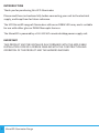
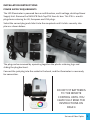
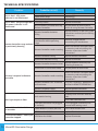
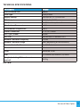
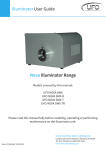
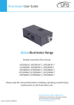
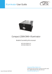
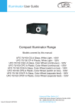
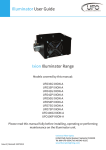
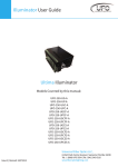
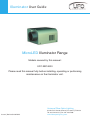
Illuminator User Guide
MicroLED Illuminator Range
Models covered by this manual:
UFO MIC4000
Please read this manual fully before installing, operating or performing
maintenance on the illuminator unit.
Universal Fiber Optic Lighting
Issue 2 | Revised: 23072013
6119A Clark Center Avenue | Sarasota | FL34238
Tel: 941-343-8115 | Fax: 941-296-7906
www.fiberopticlighting.com
INTRODUCTION
Thank you for purchasing this UFO illuminator.
Please read these instructions fully before connecting your unit to the electrical
supply, and keep them for future reference.
The UFO MicroLED range of illuminators utilises an RGBW LED array and is suitable
for use with either glass or PMMA fiber-optic harness
The MicroLED is powered by a 100-240 VAC remote desktop power supply unit.
IMPORTANT
THIS PRODUCT MUST BE INSTALLED IN ACCORDANCE WITH THE APPLICABLE
INSTALLATION CODE BY A PERSON FAMILIAR WITH THE CONSTRUCTION AND
OPERATION OF THE PRODUCT AND THE HAZARDS INVOLVED.
2
MicroLED Illuminator Range
INSTALLATION INSTRUCTIONS
POWER SUPPLY REQUIREMENTS
The LED Illuminator is powered from a multifunction, multi-voltage, desk top Power
Supply Unit. Remove the SW4047B Desk Top PSU from its box. This PSU is a multiplug device catering for UK, European and USA plugs.
Select the correct plug and slide it into the receptacle until it clicks securely into
place as shown below:
The plug can be removed by squeezing together the plastic retaining lugs and
sliding the plug back out.
Connect the jack plug into the socket in the back, and the illuminator is now ready
for connection.
DO NOT FIT BATTERIES
TO THE REMOTE
CONTROL UNTIL YOU
HAVE FULLY READ THE
INSTRUCTIONS ON
PAGE 4
Universal Fiber Optics
3
CONNECTION
There are 2 connections required – the fiber port and the mains supply. The fiber port should
be connected first. Connect and secure the fiber optic connector into the silver collar and
secure using the M5 locking screw
Plug the mains plug into the electrical supply socket. Switch on power the led Indicator will
illuminate and the illuminator will start up automatically. If no light is produced consult the
TROUBLESHOOTING section
NOTE: THESE LIGHT SOURCES ARE NOT MAINS DIMMABLE.
MIC4000 REMOTE CONTROLLER
Specification:
Description
Details
Comments
Power
2 X AAA batteries
Range
30 metres
Measured in free space, may be attenuated by
obstructions or other RF devices
Frequency
2.4GHz
Approved for use in UK, Europe and USA
Batteries – With The LED Illuminator powered up as described above, remove the rear cover
on Remote Controller. Taking care not to touch any of the front cover buttons, insert the
batteries. If you touch the remote control buttons when inserting the batteries it WILL effect
the operation of your Remote Control. If you do accidentally touch any of the buttons,
remove the batteries and start again.Once the batteries are inserted do not use the Remote
Control for 3 seconds.
DO NOT TOUCH THE
BUTTONS WHILST
INSERTING
BATTERIES
Test remote control functions as detailed on page 5. The Remote Controller is “matched” to
the Illuminator at the factory. If the Remote Controller is not matched or an additional or
replacement Remote Controller is required (see NOTE 2) for the Illuminator proceed to the
Matching Mode as follows. If a Remote Controller is to be removed from control of a
Illuminator proceed to Unmatching Model on page 5.
4
MicroLED Illuminator Range
REMOTE OPERATION
2. OFF
1. ON
4. Indicator Light
3. Color Ring
5. Speed +
6. Brightness +
9. Mode +
7. Brightness -
10. Mode -
8. Speed -
No
01
02
03
04
05
06
07
08
09
10
Description
Button
Button
Color Ring
Indicator
Button
Button
Button
Button
Button
Button
Function
Power ON
Power OFF
Touch control all colors (White not available)
Indicates Controller active when buttons pressed
Increase color cycle speed
Increase Brightness
Decrease Brightness
Decrease Color cycle speed
Mode + Step up through Color cycle programmes
Mode - Step down through Color cycle programmes
REMOTE CONTROLLER OPERATION
Matching Remote to Illuminator – Remove the power plug from the rear of the Illuminator,
then replace and once the Indicator Light (4.) lights, touch button 5 within 3 seconds, the
Illuminator will “blink” twice slowly indicating that the Remote Controller is matched to the
Illuminator.
Unmatching Remote from Illuminator - Remove the power plug from the rear of the
Illuminator, then replace and once the Indicator Light (4.) lights, touch and hold button 5
within 3 seconds and the Illuminator will “blink” 9 times indicating that the Remote
Controller is unmatched from the Illuminator.
Universal Fiber Optics
5
Mode Function Programme List
No
Mode
Brightness
To revert to 1 (Static White) at any
time touch Color Ring then Mode+
Not Adjustable
Color Ring control – brightness
adjust Color only, not White. To
revert to 2 (Color Ring) at any time
touch color ring
Adjustable
Adjustable
No White
Adjustable
Adjustable
Red, Green, Blue & White
Adjustable
Adjustable
Red, Green, Blue & White
Adjustable
Adjustable
White and Colors mixed
Adjustable
Adjustable
Red & White
Adjustable
Adjustable
Blue & White
Adjustable
Adjustable
Green & White
Static White
2
White and Colors
Adjustable
mixed
4
5
6
7
8
9
All Colors fade
change
RGBW fade
change
RGBW snap
change
7 Colors snap
change
2 Colors snap
change
2 Colors snap
change
2 Colors snap
change
Comment
Not Adjustable
1
3
Speed
Adjustable
10
1 Color Flash
Adjustable
Adjustable
Red
11
1 Color Flash
Adjustable
Adjustable
Blue
12
1 Color Flash
Adjustable
Adjustable
Green
13
1 Color Flash
Adjustable
Adjustable
White
14
All Colors snap &
fade
Adjustable
Adjustable
Random
NOTES
Mode Buttons – This is not a loop, i.e. touching the Mode+ button will not eventually bring
you back to Mode 1. To revert to Mode 1, either touch Mode – button repeatedly to step back
up through the Mode numbers, or touch Color Ring then Mode+
Color Ring –The Color Ring can be used to select individual colors by touching the ring and
sliding your finger around the ring,
Brightness – brightness can be increased or reduced in any mode using buttons 6 & 7
Cycle Speed – speed of color cycling in Modes 3 to 14 can be adjusted using buttons 5 & 8
6
MicroLED Illuminator Range
REMOTE RANGE WALK TEST
Once the Illuminator is fully installed carry out a complete range walk test and record the range in the
table below. This information is essential for maintenance purposes to determine if the
range/sensitivity is reducing and also to record dead areas within the Remote Controller’s range due to
RF obstructions and/or RF interference.
NOTE 2: Where a Illuminator has more than one Remote Control, reduction in operating range may be
experienced when both (or multiple) Remote Controls are used simultaneously.
Description
Date
Max Range
Controller 1
Controller 2
Controller 3
Dead Areas
STANDALONE OPERATION
To disable the remote and revert to manual operation press one of the buttons on the rear of the
Illuminator. The Illuminator will now respond to manual commands from the 2 control buttons as
detailed below
OPERATION
The LED illuminator has 2 color cycles each with 3 different speed settings as detailed below
Cycle
Color 1
Color 2
Color 3
Color 4
Color 5
Color 6
Color 7
1
White
Red
Orange
Jade
Green
Cyan
Blue
2
Pink
Red
Orange
Jade
Green
Cyan
Blue
Universal Fiber Optics
7
The Illuminator is controlled using the 2 push buttons on the rear of the unit.
The Lower button STOPS and STARTS the color Cycle
The Upper button is used to select the Cycle speed as follows. Push the Lower button
repeatedly until the color White is displayed. The illuminator is now in Cycle 1 speed A as
detailed below. Each push reduces the speed. On the third push the color Red will be
displayed. The illuminator is now in Cycle 2 speed A
Cycle
SPEED A - Fastest
SPEED B - Slower
SPEED C - Slowest
1 (White Start)
Push Once
Push Once
Push Once
2 (Red Start)
Push Once
Push Once
Push Once
At any time the cycle can be stopped on a color and started again using the Lower push
button
To disable manual operation and revert to remote controller operation, recycle the power to
the Illuminator. The Remote Controller may need to be matched to the Illuminator as
detailed on page 5.
DMX OPERATION
The MicroLED4000M is programmed as a Master unit (See Mode designation label on rear of
unit) and is capable of interlinking to a MicroLED Slave Illuminator using a RJ45 cable. In this
Master /Slave configuration the Slave Illuminator will follow the Master Illuminator, but no
control from a remote DMX controller is possible. Remote DMX control can only be achieved
using MicroLEDSLAVE Illuminators. See MicroLEDSLAVE User Guide for DMX wiring
connections
8
MicroLED Illuminator Range
MAINTENANCE
Please note that a record of all maintenance MUST be kept in the table below, indicating what
maintenance was undertaken and when.
Date
Maintenance Undertaken
Universal Fiber Optics
9
TECHNICAL SPECIFICATIONS
Problem
Unit is dead - LED power
indicator is not illuminated
Unit is dead - no light output but
LED power indicator is still
illuminated
Probable cause(s)
Remedy
Mains supply off
Loose mains plugs
PSU failed
LED array failure
Check supply and reinstate
Check plugs
Replace PSU
Replace Illuminator
May have been switched off using
Remote Controller
Recycle power to Illuminator or
switch on using Remote Controller
Remote Controller batteries
failing
Replace batteries as per user guide
instructions and carry out matching
if necessary
Something new causing
interference within operating
Remote Controller range reduced range
or persistently freezing
Check for another device
transmitting RF interference
Power the Remote controller down
by removing and reinstalling the
Remote Controller needs resetting
batteries as per User Guide
instructions
Unit won’t respond to Remote
Controller
Remote Controller failing
Replace Remote Controller
Illuminator Receiver Failing
Replace Illuminator
Remote Controller batteries failed
Replace batteries and carry out
matching if necessary
Illuminator in stand alone mode
Recycle power to Illuminator
Power the Remote Controller down
by removing and reinstalling the
Remote Controller needs resetting
batteries as per User Guide
instructions
Remote Controller not “matched”
to Illuminator
Carry out “matching” procedure as
detailed in REMOTE OPERATION
Remote Controller failed
Replace Remote Controller
Illuminator Receiver Failed
Replace Illuminator
Unit needs cleaning
Carefully clean LED lens with dry
cloth
Clean Fiber common end
Poor Light output on fiber
Fiber port connector not plugged
in correctly
Ensure plugged in correctly and
secured with locking screw
Lower Button has been pressed
Press Lower button once
LED Driver has failed
Replace Illuminator
In Stand Alone Mode - Color cycle
LED Driver has failed
cannot be stopped
Replace Illuminator
In Stand Alone Mode - Stationery
on one color
10 MicroLED Illuminator Range
TECHNICAL SPECIFICATIONS
Description
Details
Port connector size
30mm
Fiber type
Glass/PMMA
Supply voltage
100-240V AC, 47- 63 Hz.0.58A
PSU Output
12V DC, 2A, 24W Maximum
LED Power
2 - 5W in color cycle mode
Min Ambient Temperature
-10ºC
Max Ambient Temperature
+45ºC
Power Connection
2.1 x 5.5 x 12mm
LED Type / Model
RGBW
LED Life
50,000 hours in ambient 25ºC
Remote Controller Frequency
2.4Ghz
Remote Controller Range
30m (depending on environment)
Remote Controller Power
2 x AAA Batteries
Material
Aluminum
Color
Anodised Silver
Size
(L)190mm x(W) 68mm x (H)75mm
Weight (including PSU and remote
control)
0.68kg
NOTES:
Universal Fiber Optics
11
Universal Fiber Optic Lighting
6119A Clark Center Avenue | Sarasota | FL34238
Tel: 941-343-8115 | Fax: 941-296-7906
www.fiberopticlighting.com