1
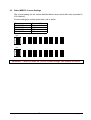
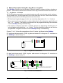
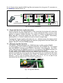
Mclennan Servo Supplies Ltd.
User Manual
for
SimStep
Single Axis
Stepper Drive & Controller
D
User Manual for SimStep
Single Axis Stepper Motor Drive and Controller
Mclennan Drg. No. 3400 Issue D
Associated Documents:
MSE570 E2 Data Sheet
PM600 Manual
Software:
McTerminal Terminal and Monitor Program
The associated documents are available from the technical documents section of our web site
www.mclennan.co.uk
SAFETY NOTICE!
Position control systems are inherently hazardous. Even a small motor, if
coupled to a leadscrew, gearbox, or any other form of mechanism that
provides a mechanical advantage, can generate considerable force and
could cause serious injury. Incorrect operation can also lead to damage to
the motor or associated machinery. It is essential that the purpose of the
various fault detection features built into the SimStep’s PM600 controller be
fully understood and used correctly.
Mclennan Servo Supplies Ltd.
22 Doman Road,
Yorktown Industrial Estate,
Camberley,
Surrey,
GU15 3DF
UK
Telephone: +44 (0)8707 700 700
FAX:
+44 (0)8707 700 699
Sales EMAIL:
[email protected]
Technical support EMAIL: [email protected]
The manufacturer reserves the right to update the data used in this manual in line with
product development without prior notice.
SimStep Manual - 3400 Iss. D
7th June 2004
page 1
CONTENTS
1
DESCRIPTION .......................................................................................................................................... 3
1.1 REAR VIEW: .................................................................................................................................. 4
1.2 LINK SETTINGS .............................................................................................................................. 6
2
EXTERNAL INTERFACE CONNECTIONS ....................................................................................................... 7
3
CABLES ................................................................................................................................................. 10
3.1 MOTOR AND LIMIT/DATUM CABLES................................................................................................ 10
3.2 ELECTRO-MAGNETIC COMPATIBILITY (EMC) ................................................................................. 10
3.3 ENCODER CABLES ....................................................................................................................... 11
3.3.1 Typical Motor Encoders .................................................................................................. 11
4
MOTOR CONNECTIONS ........................................................................................................................... 12
4.1 COLOUR CODE FOR 8 LEAD MOTORS: ........................................................................................... 12
4.2 CONNECTING TO THE MSA889 JUNCTION BOX ............................................................................ 13
4.3 CONNECTION OF LIMITS AND DATUM ............................................................................................ 14
4.3.1 Datum Position................................................................................................................ 15
4.3.2 Using Over-travel limits as datum inputs. ....................................................................... 15
5
POWER SUPPLY UNIT............................................................................................................................. 16
6
MSE570 STEPPER DRIVE...................................................................................................................... 17
6.1 GENERAL SET-UP:....................................................................................................................... 17
6.2 CURRENT SETTING ...................................................................................................................... 17
6.3 OTHER MSE570 CURRENT SETTINGS .......................................................................................... 18
7
MANUAL OPERATION USING THE JOG BOX OR JOYSTICK .......................................................................... 19
7.1 JOG BOXES - JC SERIES ............................................................................................................. 19
7.2 SINGLE AND DUAL AXIS JOG BOX OPERATION............................................................................... 20
7.3 MULTI-AXIS JOG BOX OPERATION ................................................................................................ 20
7.4 JOYSTICK - JC SERIES ................................................................................................................ 21
7.5 JOYSTICK OPERATION.................................................................................................................. 21
8
PM600 INTELLIGENT STEPPER MOTOR CONTROLLER ............................................................................. 22
8.1 GENERAL .................................................................................................................................... 22
8.2 SETTING UP THE ENCODER (CLOSED-LOOP CONTROL MODES ONLY)............................................ 22
8.2.1 Encoder Termination ...................................................................................................... 22
8.2.2 Encoder Scaling.............................................................................................................. 23
8.2.3 Encoder Direction ........................................................................................................... 23
8.3 PROGRAMMING VIA THE RS232 INTERFACE .................................................................................. 23
8.4 GENERAL COMMAND STRUCTURE ................................................................................................ 25
8.5 EXAMPLES OF COMMAND STRUCTURE .......................................................................................... 25
9
I/O CABLE AND BREAKOUT BOX ............................................................................................................. 26
9.1 ISOLATION ................................................................................................................................... 27
9.2 TYPICAL CONNECTIONS ............................................................................................................... 27
9.3 READ PORTS ............................................................................................................................... 27
9.4 WRITE PORTS ............................................................................................................................. 28
9.4.1 Inductive Loads............................................................................................................... 28
10
SIMSTEP EXAMPLE SEQUENCE............................................................................................................... 28
10.1 SEQUENCE DEFINITIONS .............................................................................................................. 28
10.2 CONFIGURATION .......................................................................................................................... 29
10.3 RUN SEQUENCE .......................................................................................................................... 29
11
ORDER CODES ...................................................................................................................................... 30
11.1 SYSTEM ...................................................................................................................................... 30
11.2 MOTOR ENCODERS ..................................................................................................................... 30
11.3 CABLES ...................................................................................................................................... 30
11.4 JUNCTION BOXES ........................................................................................................................ 30
11.5 JOG BOXES & JOYSTICK .............................................................................................................. 30
11.6 EMC FERRITES ........................................................................................................................... 30
12
LIMITATIONS OF USE .............................................................................................................................. 31
SimStep Manual - 3400 Iss. D
7th June 2004
page 2
1 Description
The system is a single axis stepper motor control and drive rack. Motor motion is
commanded either from a computer or from a terminal via the RS232 (or RS485) serial
data port or from a manual Jog Box or Joystick controller. The controller can drive stepper
motors in open-loop (step counting) mode or encoded motors/mechanisms in closed-loop
mode.
The controller consists of:
1
1
1
1
MSE570-Evo2 3.5A Stepper Drive
PM600 Motor Controller
MSB867 Backplane
MSE779 Power Supply Board
These are mounted in a 3U high 28HP rack unit. The SimStep is supplied with a mains
lead, an RS232 cable and an RS232 terminator. A range of standard motor, encoder,
limits/datum and I/O cables are available.
Fig.1.1 SimStep Front View
The system has a PM600 controller and a MSE570 Stepper drive powered by a power
supply based on the MSE779 power supply board.
The PM600 controller and the MSE570 plug into the MSB867 backplane. Step, clock and
direction signals from the PM600 are fed to the MSE570 Stepper drive. The bipolar
stepper motor is connected to the MSB867 backplane via a rear panel connector.
SimStep Manual - 3400 Iss. D
7th June 2004
page 3
The PM600 position controller generates the clock and direction signals for the MSE570
drive in response to move commands.
The PM600 enable output is connected to the enable input of the MSE570 drive. If the
PM600’s enable output is turned off (e.g. as a result of an error) the motor current will
turned off. The enable output may be turned off by an AB abort command, or reset (turned
on) by an RS command (see Section 6.4).
The Idle output from the PM600 is connected to the current reduction input on the
MSE570 to reduce the motor current to about 25% when the motor is not moving.
An incremental encoder can be fitted to the motor or mechanism to monitor the movement
of the mechanism. The quadrature signals from the encoder are connected to the PM600
to allow passive closed-loop operation. The system is initially supplied with the PM600
configured for open-loop operation. The PM600 must be reconfigured for closed-loop
operation (see Section 8.2).
The MSB867 has a multi-axis jog receiver; it allows the PM600’s Jog inputs to be
controlled by a JC809 Jog Box. The axis addresses shown on the JC809 may be
changed by altering the settings of the rotary switches accessible by removing the top
cover of the unit.
The power supply provides +24V (nominal) to energise the supply rail on the PM600
controller, and +40V (nominal) to energise the supply rail on the MSE570 drive.
The PM600 manual referred to in this document can be found on www.mclennan.co.uk.
1.1
Rear View:
Fig.1.2 SimStep Rear Panel
Connections for motors, limits/datum, I/O, encoders, RS232 and mains are taken from the
MSB867 backplane to connectors on the rear panel.
SimStep Manual - 3400 Iss. D
7th June 2004
page 4
The mains input is a filtered IEC inlet.
The MOTOR connector has outputs from the PM570-Evo2 stepper drive to connect to a
bipolar stepper motor.
WARNING! Serious damage will occur if the motor is connected or disconnected
whilst the power is switched on. Allow 30 seconds after switching off.
The LIMITS/DATUM connectors have inputs for the Upper and Lower Limit switches, a
Datum Approach switch and a Datum Stop switch. The connections to the Limit switch
inputs must be made for normal operation of the PM600 controllers.
Limit switches must not be used as a safety device or part of a safety system for
ensuring the safety of persons
The ENCODER connector is for the position encoder input. It has a +5V supply to
energise the encoder, complementary quadrature inputs and complementary index inputs.
The JOG A and JOG B connectors have inputs for Jog pushbuttons, a Joystick control
and data connections for a JC809 Jog Box.
They have connections for Jog, Jog- and Jog Fast pushbuttons compatible with a JC100
Jog Box and +5V, 0V Joystick input and Joystick centre tap compatible with a JC400
Joystick. The JC100 and JC400 may be plugged into either connector.
If using a JC809 Multi axis jog box, the axis address that is assigned to Jog is set on the
MSB867 interface board using a rotary switch (see section 5.2). The JC809 can be
connected to other axes by using a ‘Jog daisy-chain’ cable plugged into the vacant JOG A
or JOG B connector. The Jog Terminator supplied with the JC809 must be plugged into
the vacant connector in the last axis in the daisy-chain.
The I/O connector has inputs and outputs from PM600’s Read inputs and Write outputs.
There are also connectors for RS232 IN for connecting to the computer or terminal that
supplies the control data and RS232 OUT for connecting either to a subsequent control
rack (daisy-chain) or to an RS232 terminator. These connectors can also be configured for
RS485 communications (see section 1.2).
Note: The RS232 Terminator supplied with the control system must be fitted to the last
unit in the daisy-chain. This allows both replies from, and commands sent to, the controller
to be echoed back.
WARNING! To avoid overheating, the vents in the top and bottom of the unit must
be unobstructed at all times.
SimStep Manual - 3400 Iss. D
7th June 2004
page 5
1.2
Link Settings
The control operation of the SimStep can be configured by means of links fitted to the
MSE867. The links can be accessed by removing the rear top cover of the unit.
LK8
LK7 to LK1
Fig. 1 Link Location
Link
LK1
LK2
LK3
LK4 to LK7
LK8
Action
Select automatic current reduction from PM600 idle output
Drive over-temperature activates PM600 abort stop input
Drive overload activates PM600 abort stop input
1-2 selects RS485, 2-3 selects RS232
Select internal (on) or external (off) abort stop
Default
On
On
On
RS232
Internal
LK1
If LK1 is on, the current to the motor will be reduced to about 25% of the current
set on the drive when the motor has finished its move and the controller returns to
Idle. The primary use of this function is to reduce the heating effect caused by the
motor. It is not intended to produce a precise holding-torque.
If LK1 is removed, the motor current will remain at the current set on the drive.
This setting is usually only needed when a high holding-torque is required. E.g.
when driving a mechanism with an offset load.
LK2
If LK2 is on, an over-temperature fault detected on the drive output stage will
cause the controller abort stop input to be activated.
LK3
Likewise if LK3 is on, an overload fault detected on the drive output stage will
cause the controller abort stop input to be activated.
LK4-7 These two position links select either the RS232 or RS485 communication
interfaces. When the links LK4 to LK7 are all in the 1-2 position, RS485 is selected
and when all in the 2-3 position, RS232 is selected.
If using RS485 communication, The last SimStep in the line should have SW3-8
on the PM600 switched to the ON position. This selects a 100Ω terminating
resistor. See figs 8.2 and 8.3 in section 8.3.
LK8
If LK8 is removed (off) the external ‘Abort Stop’ input selected. Pins 7 and 14 on
the Limits/Datum connector must be linked (via a normally-closed contact or
switch) to enable moves.
SimStep Manual - 3400 Iss. D
7th June 2004
page 6
2 External Interface Connections
MAINS supply
Connector type: IEC chassis plug
Terminal
Connection
L
Live input 115/230V AC
(Internally selectable)
N
Neutral input
E
Earth. THIS UNIT MUST BE EARTHED
MOTOR
Connector type: HAN-4A socket
Mating Cable: 507MOCxx892 (xx = length)
Terminal
Connection
1
Motor Phase A+
2
Motor Phase A3
Motor Phase B+
4
Motor Phase BE
Screen
LIMITS/DATUM
RED
Connector type: 15 way ‘D’ Plug
Mating Cable: 507LDCxx894 (xx = length)
Terminal
Connection
1
2
0V
3
Upper Limit Input 4
Lower Limit Input 5
Datum Approach Input 6
Datum Stop Input 7
Abort Stop – (selected by internal link LK8)
8
9
10
Upper Limit Input + (24V)
11
Lower Limit Input + (24V)
12
Datum Approach Input + (24V)
13
Datum Stop Input + (24V)
14
Abort Stop + (24V)
15
Link pins 3 and 10 to enable positive moves
Link pins 4 and 11 to enable negative moves
Link pins 5 and 12 for fast datum search
If external ‘Abort Stop’ selected, link pins 7 and 14 to enable moves.
SimStep Manual - 3400 Iss. D
7th June 2004
page 7
ENCODER
BLUE
Connector type: 15 way ‘D’ socket
Mating Cable: 507ENCxx893 (xx = length)
Terminal
Connection
1
2
0V
3
Channel A4
Channel B5
Channel I6
7
8
9
+5V
10
11
Channel A+
12
Channel B+
13
Channel I+
14
15
I/O
YELLOW
Connector type: 25 way 'D' socket
Mating Cable: 507IOCxx895 (xx = length)
Terminal
Connection
1
Write Port 1
2
Write Port 2
3
Write Port 3
4
Write Port 4
5
Write Port 5
6
Write Port 6
7
Write Port 7
8
Write Port 8
9
Write Port Common (Isolated Supply)
10
+VLL (Controller Supply)
11
12
13
14
Read Port 1
15
Read Port 2
16
Read Port 3
17
Read Port 4
18
Read Port 5
19
Read Port 6
20
Read Port 7
21
Read Port 8
22
Read Port Common (Isolated 0V)
23
0V (Controller 0V)
24
25
Refer to PM600 Manual sections 2.18 and 3.16 for typical connections.
SimStep Manual - 3400 Iss. D
7th June 2004
page 8
JOG A and JOG B
GREEN
Connector type: 15 way 'D’ socket
Compatible with JC100, JC400 and JC809 manual controls
Terminal
Connection
1
Jog Common (~+24V)
2
0V
3
Jog + Input
4
Jog – Input
5
Jog Fast Input
6
7
8
9
Joystick Supply (+5V)
10
Joystick Input
11
12
Joystick Centre Tap Input
13
14
Data A
15
Data B
RS232 IN
Connector type: 9 way 'D' type socket
Terminal
RS232 Connection
1
2
Transmit Data
3
Receive Data
4
5
0V
6
7
CTS
8
RTS
9
RS485 Connection
RS485-A
RS485-B
RS232 OUT
Connector type: 9 way 'D' type plug
Terminal
RS232 Connection
1
2
Receive Data
Link to echo replies
and commands
3
Transmit Data
4
5
0V
6
7
RTS
Link to echo replies
and commands
8
CTS
9
SimStep Manual - 3400 Iss. D
7th June 2004
RS485 Connection
RS485-A
RS485-B
page 9
3 Cables
3.1 Motor and Limit/Datum cables
Motor and limit/datum cables fitted with connectors to plug into the rear panel of the
SimStep may be specified. The available lengths are shown below. The motor cables
have a connector on both ends, which can be connected either to the connector fitted to
the stepper motor or to the stepper motor wires via an MSA889 Junction Box.
Likewise, the Limit and Datum connections can be made either by connecting to the
socket on the end of the cable or via an MSA889 junction box. The connections to the
MSA889 junction box are shown in figures 4.2 and 4.3.
Limit/Datum Cables
Length
1m
2m
3m
5m
10m
Type
507LDC01894
507LDC02894
507LDC03894
507LDC05894
507LDC10894
Limit/Datum Cable
Junction Box
Type MSA889
Motor Cable
Motor Cables
- Limit
Datum
+ Limit
Motor
Length
1m
2m
3m
5m
10m
Type
507MOC01892
507MOC02892
507MOC03892
507MOC05892
507MOC10892
Fig. 3.1 Motor and Limit/Datum Cables
3.2
Electro-magnetic Compatibility (EMC)
The SimStep complies with EN-50081-1 and EN50082-1 when properly with cables that
use EMC connectors. The cable used to connect the motor to the drive should be a
screened, twisted pair type. The screen should be connected at both ends of the cable.
On the drive end, the screen should be connected to earthed metalwork of the case and
on the motor end, the screen should be connected to the motor body.
The EMC profile may be improved by fitting ferrite sleeves to the motor cables. For cable
diameters from 7mm to 8.5mm use RS part number 260-6492. For cable diameters from
8.5mm to 10mm use RS part number 309-7962.
SimStep Manual - 3400 Iss. D
7th June 2004
page 10
3.3 Encoder Cables
The SimStep can be connected to the encoder via an encoder cable that is equipped with
connectors at each end. One connector plugs into the controller, the other into the motorencoder extension cable as shown in fig 3.2.
Alternatively, if the motor has a connector box, the cable can be plugged in directly.
.
Encoder Cables
- Limit
Datum
+ Limit
Type
Cable length
507ENC01893
507ENC02893
507ENC03893
507ENC05893
507ENC10893
1m
2m
3m
5m
10 m
Motor-encoder
Fig. 3.2 Encoder Cable
3.3.1 Typical Motor Encoders
Frame size
Motor Encoder
Size 23
23HSX-206 CI 500L
23HSX-306 CI 500L
Size 34
34HSX-108 RI 500L
34HSX-208 RI 500L
SimStep Manual - 3400 Iss. D
Order Code
301HSE00053
301HSE00054
301HSE00055
301HSE00056
7th June 2004
page 11
4
Motor Connections
4.1
Colour Code for 8 lead motors:
The motor will have eight leads that can be identified as shown in figure 4.1.
1
1’
3’ 3
2
2’
4’
4
Fig. 4.1 Eight lead 23 & 34 frame size motors
Motor
Lead identification
1
1’
2’
Red
White/
White/
Red
Yellow
Red
Black
White
HS
Series
or
23HSX
Red
34HSX
Red
White/
Red
White/
Red
White/
Yellow
White/
Yellow
2
Yellow
3
Black
White/
Red
Yellow
White/
Green
Orange
Yellow
Black
3’
White/
Black
White/
Black
White/
Orange
White/
Black
4’
White/
Orange
Orange
4
Orange
White/
Brown
White/
Orange
Brown
Green
Orange
The motor can be connected into the MSA889 junction box as shown in fig. 4.4. Internal
links select parallel or series operation. This function is shown in figures 4.2 and 4.3.
Phase A
Phase A’
Phase B
Phase A
2
2’
1’
1
3
3’
4’
4
Phase A’
Phase B
Phase B’
2
2’
1’
1
3
3’
4’
4
Phase B’
Fig. 4.2 Coils in Parallel
Fig. 4.3 Coils in Series
The maximum drive current for coils wired in parallel is the unipolar motor phase current
rating x √2. The maximum drive current for coils wired in series is the unipolar motor
phase current rating / √2.
To reverse motor direction, swap the connections to one phase. E.g., swap B with B’.
SimStep Manual - 3400 Iss. D
7th June 2004
page 12
4.2
Connecting To The MSA889 Junction Box
Motor Lead connections
57 mm
4 Lead motors
1’
Link for parallel
Operation
1
1’
2’
2
3
3’
4’
4
126 mm
8 Lead motors
Motor Lead
507MOCxx892
1
1’
2’
2
3
3’
4’
4
Motor leads
1
1’
2’
2
3
3’
4’
4
Junction Box MSA889
Fig. 4.4 Parallel Motor Coil Connections
57 mm
Link for series
Operation
126 mm
Motor Lead
507MOCxx892
Motor Lead connections
Motor Leads
8 Lead motors
1
1’
2’
2
3
3’
4’
4
1
1’
2’
2
3
3’
4’
4
Junction Box MSA889
Fig. 4.5 Series Motor Coil Connections
SimStep Manual - 3400 Iss. D
7th June 2004
page 13
4.3
Connection of Limits And Datum
Limit / datum connections
0VLL
+VLL
Upper Limit
+VLL
Lower Limit
+VLL
Datum App
+VLL
Datum stop
+VLL
Abort stop
Limits datum cable
507LDCxx894
1’
+over-travel limit
- over-travel limit
datum approach *
datum stop
abort stop **
Allow sufficient deceleration over-travel
deceleration
deceleration
zone
working zone
zone
- Limit
+ Limit
Fig. 4.5 Limit/Datum Connections
All limit and datum signal inputs should utilise normally closed contacts.
Note*
a)
b)
Note **
The datum approach signal is not always required. This is the case when:
The motor is operated at slow (creep speed) since it is not necessary to
decelerate before stopping at the datum point. In this case the datum
approach terminals should not be connected.
When the controller is configured to utilise the high-speed datum registration
feature. In this case, the datum approach connections should be linked.
This connection enables an external open contact to abort a move. However
for this feature to be utilised it is necessary to remove an internal link LK8
within the controller.
It should be noted that the limit switches should be placed sufficiently within the total travel
distance to allow the motor to decelerate from high speed.
They should also be mounted for sliding operation, so that they do not become crushed on
first use. No mechanism can decelerate instantaneously.
SimStep Manual - 3400 Iss. D
7th June 2004
page 14
4.3.1 Datum Position
The datum position is detected as the datum stop switch opens. It is also summed with
the encoder index signal (if fitted). For further information, refer to the Datum Search
Strategies section (2.13) of the PM600 manual.
4.3.2 Using Over-travel limits as datum inputs.
0VLL
+VLL
Upper Limit
+VLL
Lower Limit
+VLL
Datum Approach
+VLL
Datum Stop
+VLL
Abort stop
In applications where space is limited, the over-travel
limit switches may also be used as the datum stop
switch. In the example shown the lower limit switch is
also connected to the datum stop input and the
controller is configured to utilise the high-speed
datum approach facility.
Fig. 4.6 Limit/Datum Connections
SimStep Manual - 3400 Iss. D
7th June 2004
page 15
5 Power Supply Unit
The power supply unit used in this system has been designed to energise an MSE570
stepper drive and a PM600 Position Controller.
It provides the unregulated logic supply of +24V (nominal) to the PM600, and an
unregulated supply of +40V (nominal) to the MSE570.
There is a mains fuse fitted in the mains inlet, its rating is 2A anti-surge. There are two
front panel fuseholders that protect the DC outputs of the power supply. The rating of the
fuses are 3.15A for the motor rail and 1A for the logic rail.
The mains voltage may be changed from 230V to 115V by changing the position of the
links on the MSE779 PCB.
SEL1
Fig. 5.1 Mains Voltage Selector
SimStep Manual - 3400 Iss. D
7th June 2004
page 16
6 MSE570 Stepper Drive
The MSE570 stepper drive translator is a 3.5A per phase bi-polar stepper drive.
The clock and direction signals from the PM600 controller are converted into chopped,
constant current drive levels to energise a bipolar stepper motor.
The step sequence is set to half step. Using a hybrid type stepper motor, 400 steps per
revolution will be obtained.
A thermal sensor protects the output devices in case of overheating. If the drive
temperature exceeds 80° C, the thermal sensor will operate. With the switch settings
shown below, the drive is disabled (SW1-1=on) and the condition is latched (SW1-2=on).
The latched condition can only be reset by removing the power.
SW1
SW2
Fig. 6.1 MSE570 Set-up Switches
6.1
General Set-up:
SW1
1
2
3
4
DT
LT
CC
SS
Off
6.2
Disable on Overtemperature - on
Latch Overtemperature - on
Current Control Type - slow
Slave Sync – off
On
Current Setting
As delivered the motor phase current is set to 3.5A/phase.
SW2
1
2
3
4
Off
On
SimStep Manual - 3400 Iss. D
7th June 2004
page 17
6.3
Other MSE570 Current Settings
The current setting for the motors detailed below when wired with coils in parallel is
3.5A (default).
Current settings for motors wired with coils in series.
Motor
23HSX-206
23HSX-306
34HSX-108
34HSX-208
Current (A)
2.1
2.1
2.7
2.7
SW2
1
2
3
4
Off
On
0.0A
0.5A
0.9A
1.2A
1.3A
1.6A
1.85A
2.1A
2.5A
2.7A
2.9A
3.0A
3.1A
3.3A
3.5A
SW2
1
2
3
4
Off
On
2.3A
WARNING! Failure to make the correct current settings can damage the motor
SimStep Manual - 3400 Iss. D
7th June 2004
page 18
7 Manual Operation Using the Jog Box or Joystick
The SimStep controller can be operated in manual mode by means of either a jog box or
joystick. These devices should be connected to the Jog connectors on the rear of the unit.
7.1
Jog Boxes - JC Series
JC Series Jog boxes provide a convenient way to manually control motor control systems.
Three models, the JC100 single-axis, the JC200 dual axis and the JC809 multi-axis are
available and provide the following manual control functions:
• Bi-directional single step (jog) function by momentary depression of ‘+’ or ‘-’ buttons.
• Slow speed continuous operation in desired direction by the depression and holding of
the ‘+’ or ‘-’ buttons. The speed of movement can be programmed using SJ command
into the SimStep during commissioning.
• Fast speed, continuous operation in desired direction by depressing & holding the ‘F’
button together with either the ‘+ or ‘- button. The fast positioning rates are can also be
programmed using SF command into the SimStep during commissioning.
Figures 7.1 to 7.3 show the connections of the JC series Jog Boxes to the SimStep.
For single axis drives specify JC100 Jog box and connect it to the green ‘D’ connector on
the SimStep as shown in fig 7.1.
Sim-Step
SINGLE
AXIS
JOG BOX
JC100
Fig. 7.1 Single axis installations
For dual axis drives specify JC200 Jog box and connect it to the green ‘D’ connector on
the SimStep as shown in fig 7.2.
AXIS
DUAL
AXIS
JOG
JC 200
JC200
Use jog link cable 507JDC05916
Note: Jog link cable is handed, identified by
the colour of the screw heads as shown
1
2
Fig. 7.2 Dual axis installations
SimStep Manual - 3400 Iss. D
7th June 2004
page 19
For 3-15 axes drives specify JC809 Jog Box and connect it to the green ‘D’ connector on
the SimStep as shown in fig. 7.3.
JC809
Use jog link cables 507JDC05916
Fit terminator
Supplied with
JC809
Fig. 7.3 3-15 axis installations
7.2
Single and Dual Axis Jog Box Operation
Jog box operation is very straightforward. Once connected, the jog box will control the
motor as follows. Pressing either the + or – button causes the motor to move in the
positive or negative rotation direction. The speed of rotation is determined by the
Slow Jog (SJ command) speed that has been set in the PM600. Momentarily
pressing the + or – buttons causes the motor to move in single steps.
Pressing the F button together with either the + or – buttons causes the motor to move
at the Fast Jog (SF command) speed that has been programmed into the PM600 (see
pages 7-48 and 7-49 of the PM600 manual)
7.3
Multi-axis Jog Box Operation
The MSB867 interfaces between the JC809 Multi-axis Jog Box and the PM600.
It communicates to the JC809 via signals transferred over a RS485 link. The outputs
from the MSB867 connect to the PM600’s Jog inputs. Connecting the ‘Jog DaisyChain’ lead between the JOG B connector on one system to the JOG A connector on
the next system allows further systems to be connected to the JC809.
A rotary switch on the MSB867 sets the axis address that is shown on the JC809. This
switch is accessible by removing the rear top cover of the unit. A setting of 0 will mean
that the axis cannot be controlled by the JC809. The default axis is 1 but any axis
between 1 and 15 can be selected. Note that axes 10, 11, 12, 13, 14 and 15 are
represented by the letters A, B, C, D, E and F respectively.
Fig. 7.4 Jog Axis Selector
SimStep Manual - 3400 Iss. D
7th June 2004
page 20
7.4
Joystick - JC Series
The JC Series Joysticks provide an alternative way to manually control motor speed.
The JC400 is a dual axis Joystick that can be used to control either one or two axes.
The JC400 is connected in a similar way to the JC100 and JC200 Jog Boxes shown in
figures 7.1 and 7.2.
7.5
Joystick Operation
In order to set the joystick parameters, the RS232 connection must be connected to a
PC.
The joystick option gives variable control of the motor speed – the further the joystick
is moved from the centre position, the faster the motor moves. Before the joystick
option can be used, the joystick centre and minimum/maximum positions must be
calibrated. Note that the SimStep is set up for Jog Box operation as standard.
The controller must then be told to accept the joystick input using the command
1JM01000000 (see PM600 manual page 7-27).
Assume that the controller is set as Axis 1 and that the joystick is in the “free” (i.e. mid
range) position. The command 1AI3 will interrogate the joystick position; the controller
will then display a value in the format 01:2126, where 01: refers to Axis 1, and 2126 is
the joystick centre position.
Now hold the joystick at one extreme of its range and repeat the 1AI3 command; note
this number and then repeat at the other extreme of the joystick range. Let us assume
that the following data are given from the 1AI3 command:
Low
1688
Centre
2126
High
2568
This means that the range either side of centre is ~440 units (note that the “centre
position” may not be exactly in the middle of the upper and lower readings).
1JC2126 This sets the centre position. A value of JC=0 will use the value of a joystick
centre tap signal, connected to Analogue input 5, to set the centre position.
1JR340 This sets the +/- range of the joystick (JR = range – 2 x JT)
1JT50
This sets the joystick threshold – this is the “deadband” around the centre
position. If the joystick is moved by less than the deadband value, the
motor will not move.
Note: You must use the 1BD (backup digiloop) command in order to store these
parameters otherwise they will be lost when power to the controller is switched off.
For further information, refer to the Joystick Calibration section (2.19) of the PM600
manual.
SimStep Manual - 3400 Iss. D
7th June 2004
page 21
8 PM600 Intelligent Stepper Motor Controller
The PM600 is a microprocessor-based unit for controlling servo or stepper motors. The
controller has a wide range of functions available; these are described in detail in the
PM600 manual included with this documentation. The SimStep will operate under manual
control with either a jog box or joystick, or can run under remote control through the
RS232 (or RS485) interface.
Basic information on the command structure and the RS232 interface is given below; the
user should refer to the PM600 manual for complete details.
8.1
General
The PM600’s switches have been set as follows:
RS232 Control
The controllers are set to axis address 1
The baud rate is set to 9600 baud
The word mode is set to 7 bits, even parity
Quiet mode is selected
Rotary switches SW1 and SW2 set the axis address. These are set to the actual
address required. SW3 sets the communication configuration. For further information
refer to the Switch Setting section (10) of the PM600 manual
The control mode has been set to open-loop stepper mode by the command 1CM11.
When using the SimStep with an encoder, the control mode can be changed to
closed-loop stepper by the command 1CM14.
8.2
Setting Up The Encoder (Closed-loop Control Modes Only)
Each edge of the quadrature signals is counted, so the number of encoder counts per
revolution will be four times the line count of the encoder.
The PM600 can be used with encoder producing either 5V TTL signals or 5V line
driver signals. The correct termination should be set. This gives maximum noise
immunity. The use of encoders with line driver type signals is recommended where the
encoder lead length will exceed 1m.
8.2.1 Encoder Termination
Switch SW4 selects the termination for the encoder signals. If using differential signals
then the encoder termination should be switched on. With 5V TTL encoders, the
encoder termination switches should be switched off.
SW4
1
2
3
O 1A
N
1B
1I
1
2
3
Single
ended
(TTL)
1
2
3
Line Driver
(Default)
Fig.8.1 Encoder Termination Configuration Switch SW4
SimStep Manual - 3400 Iss. D
7th June 2004
page 22
8.2.2 Encoder Scaling
The incoming encoder pulses are scaled by the encoder ratio (ER) formed by the
Encoder Numerator (EN) and the Encoder Denominator (ED) i.e. the number of
pulses received is multiplied by the numerator and divided by the denominator, to
become the Actual Position.
If the ratio between the number of steps and the encoder counts is 1:1 (e.g. 100 line
encoder = 400 counts per revolution mounted on a 400 step per rev motor) then the
encoder scaling factors; Encoder Numerator and Encoder Denominator can be left at
their default of 1, otherwise they will need to be changed.
If the Encoder Numerator (EN) is set to the number of motor steps per revolution and
the Encoder Denominator (ED) is set to the number of encoder counts per revolution,
then the ratio will be correct. For example, if a 400 step per revolution motor fitted with
a 500 line (2000 counts) encoder, then set the Numerator to 400 and the Denominator
to 2000 (ER400/2000 or EN400, ED2000).
8.2.3 Encoder Direction
On switch on, both the Command Position and the Actual Position will both be at zero.
Try a test move (e.g. MR1000) and query the positions with the OC and OA (or QP)
commands, to ensure the scaling is correct. If one is the negative of the other, then
the ‘sense of direction’ needs to be reversed, by either swapping the A and B signals
OR by setting the Encoder Numerator to a negative value.
8.3
Programming via the RS232 Interface
Any suitable communication programme can be used to communicate with the
SimStep controller. For example, the MyTerminal programme (available from
www.SimStep.co.uk) or the Windows Hyper Terminal programme can be used to
make the communications link.
Whichever software is used, the communications interface is set by default, as
follows:
Baud Rate
Data Bits
Stop Bits
Parity
Flow Control
9600
7
1
Even
None
Once the communications software has been set up, the remote computer should be
connected to the SimStep via the RS232 IN port. Multiple SimStep units can be
daisy-chained together to build multi-axis systems. Rotary switches SW1 and SW2 on
the PM600 card are used to set the units axis address (0 to 99). This is the address of
the serial commands that it will respond to. Each controller in a system will be set to a
different address.
The switches on the PM600 are accessible by removing the slotted top cover of the
unit. The left-hand switch SW1 sets the decade value and SW2 sets the units. They
can be set using a small screwdriver. See figures 8.2 and 8.3.
Note that the RS232 loop-back connector must be fitted to the RS232 OUT connector
of the final SimStep in the RS232 chain.
SimStep Manual - 3400 Iss. D
7th June 2004
page 23
10
1
SW3
ON
1
12345678
SW1
SW2
SW4
12345678
ON
LK1
ULOAD
1A
1B
1I
2A
2B
2I
3A
3B
LD1 LD2 LD3
P2
LK2
32
SWAP8
Fig. 8.2 PM600 Switch Positions
SW1
SW2
SW3
Fig. 8.3 Positions of PM600 Switches SW1, SW2 and SW3
SimStep Manual - 3400 Iss. D
7th June 2004
page 24
8.4
General Command Structure
The PM600 responds to a character string (sent over the RS232 interface) that
defines a command in the following way:
adXXnnn<cr> where
ad
=
address for the axis (see 8.1 above)
XX
=
command notation – all commands are two letters
nnn
=
numeric value for the command argument (if required)
<cr>
=
carriage return
Command strings must be terminated with a carriage return (ASCII 0D hex). Upper or
lower case characters maybe used for the command. Spaces in the command line are
ignored. Commands are acted upon sequentially, as they have been entered.
8.5
Examples of Command Structure
Set-up commands:
2SA5000
Set Axis 2 acceleration to 5000 steps/sec2
1LL-20000 Set Axis 1 lower software limit to –20000 steps
1QA
Query all settings for Axis 1
MOVE COMMANDS:
1MR5000
1ST
2MA-2000
2OA
Move Axis 1 relative to current position by +5000 steps
Soft stop on Axis 1
Move Axis 2 to absolute position –2000 steps
Output the encoder position of Axis 2
The SimStep controller responds to all commands once the command has been
accepted. However, not all commands can be accepted immediately. For example, a
move command sent whilst a previous command is still taking place, will be delayed
until the previous one is finished. Commands in general will have an OK response.
Some commands, however, will produce a numeric response (e.g.2OA) or produce a
string of data (e.g. 1QA).
All replies are preceded by the address of the axis that generated the response – e.g.
for axis one the replies will be preceded by 01:OK.
Important – if the set-up of the PM600 is changed then the BA (backup all command)
must be executed to save set-up values and sequences to Flash memory. If this not
done, the values will be lost on power-down.
The user may encounter error message from the controller under certain
circumstances, e.g. mistakes in commands or conflicting instructions. The messages
are usually self-explanatory; they are listed on page 8-1 of the PM600 manual.
SimStep Manual - 3400 Iss. D
7th June 2004
page 25
9 I/O Cable and Breakout Box
Eight inputs (Read Ports) and eight outputs (Write Ports) can be used for external digital
interfacing.
An I/O cable with the ‘breakout’ DIN rail mounting terminal box can be used to interface to
the SimStep without needing to make a special cable.
The I/O breakout box features screw terminals to enable the 16 Digital I/O to be
connected. The unit is DIN rail mounted so that it can be sited next to a typical PLC
control unit
85 mm
70 mm
I O Breakout Box ordering details
- Limit
Datum
+ Limit
I/O Breakout Box
1m I/O Cable
2m I/O Cable
3m I/O Cable
5m I/O Cable
Motor
506MSC00891
507IOC01895
507IOC02895
507IOC03895
507IOC05895
Fig. 9.1 I/O Breakout Box and I/O Cable
I / O Breakout box 506MSC00891 Connections:
Output Lines
Input Lines
WP1
WP2
WP3
WP4
WP5
WP6
WP7
WP8
WP com
Diode-com
+VLL
0V
RP1
RP2
RP3
RP4
RP5
RP6
RP7
RP8
RP-com
N/C
+VLL
0V
Screw Terminal connections
Fig. 9.2 I/O Breakout Box Connections
SimStep Manual - 3400 Iss. D
7th June 2004
page 26
9.1
Isolation
The Read Port inputs and Write Port outputs are opto-isolated. A +24V nominal supply
must be used as the common for these inputs. This supply can either be a separate
external supply or the SimStep’s internal +24V supply. If the internal supply is used, then
the WP-com terminal must be connected the +VLL terminal on the Breakout box and the
RP-com terminal must be connected the 0V terminal on the Breakout box. If a separate
supply is used then the WP-Com terminal must be connected to the +24V terminal of the
external power supply and the RP-Com terminal must be connected to the 0V terminal of
the external power supply. The +24V output from the external supply can be used for the
common of the switches.
9.2
Typical Connections
Typical Output Line Connections
Typical Input Line connections
WP
RP
Low current Relay
WP – com
Diode com
+VLL
0V
RP-com
+VLL
0V
Fig. 9.3 Typical Connections to the I/O Breakout Box
Typical Output Line Connections
Typical Input Line connections
WP
RP
Low current Relay
WP – com
Diode com
RP-com
+24V
0V
External
PSU
Fig. 9.4 Typical I/O Connections using an External Supply
9.3 Read Ports
The read ports can be connected to a PNP signal output, a switch, or another SimStep’s
write port.
The RP Read input Port command is used to check the operation of the read ports. This
instruction returns an eight digit binary number of either 0 or 1 characters to represent the
current state of the read port. These start with read port 8, through to 1. Referring to
figures 9.3 and 9.4, a 1 represents a closed switch and a 0 represents an open switch.
The input voltage that is considered as a logic 1 signal is 10-35V and the input voltage that
is considered as a logic 0 is 0-5V.
SimStep Manual - 3400 Iss. D
7th June 2004
page 27
9.4 Write Ports
The write ports can be connected to an indicator (LED), an opto-isolator, a low-current
relay or another SimStep’s read port. The WP(bit pattern) command is used to write to
the output port.
The bit pattern is specified as an eight digit binary number. The digits will be either
characters 0, 1 or 2 starting with write port 8 through to 1. A 0 defines that the output will
be off, a 1 defines that the output will be on and a 2 defines that the output will not
change from its current state. The power-on states of the write ports are 00000000 - i.e. all
off.
The outputs are rated at 50mA, 35V.
9.4.1 Inductive Loads
The write ports must not be reverse biased. If used to drive an inductive load such as a
relay, then protection diodes must be used. If using an MSE891, this can be done by
connecting Diode-Com to 0V (either 0V on the Breakout box or the external supply 0V).
10 SimStep Example Sequence
An example sequence is shown below. Three switches are connected to the Read Port to
control the action of the sequence and three outputs are used to monitor the action of the
sequence. One switch executes a 'home to datum' move and two switches initiate moves.
The ‘home to datum’ move must be done before the other moves can be selected.
The moves are controlled by the following inputs.
Read Port 1 = home to datum (datum search)
Read Port 2 = move to position 1
Read Port 3 = move to position 2
When the moves are completed, the following outputs turn on.
Write Port 1 = datum search complete
Write Port 2 = at position 1
Write Port 3 = at position 2
10.1 Sequence Definitions
Sequence 0 waits for the ‘Home to Datum’ input to be ‘1’ and then executes a ‘home to
datum’ (HD) move.
1ds0
1wp22222000
1wa22222221
1hd
1we
1wp22222001
1wa22222220
1xs2
1es
Sequence 0 – Search for Datum
Turn off outputs
Wait for Home input to go on
Search for datum
Wait for end of move
Turn on axis 1 homed
Wait for Home input to go off
Goto input scanning sequence
SimStep Manual - 3400 Iss. D
7th June 2004
page 28
Sequence 2 scans the read port inputs and depending on the state of the inputs executes
the moves in sequence 3 or 4. After the move is complete, the operation goes back to
scanning the read port inputs.
1ds2
1it22222212
1xs3
1it22222122
1xs4
1xs2
1es
Sequence 2 - Scan for Move inputs
Is Move 1 input on
Yes - do move
Is Move 2 input on
Yes - do move
No rescan inputs
1ds3
1wp22222002
1ma1000
1we
1wp22222012
1wa22222202
1xs2
1es
Sequence 3 - Move 1
Turn off 'At Position' outputs
Move to position 1000
Wait for end of move
Turn on 'At Position 1' output
Wait for Move 1 input to go off
Goto input scanning sequence
1ds4
1wp22222002
1ma5000
1we
1wp22222102
1wa22222022
1xs2
1es
Sequence 4 - Move 2
Turn off 'At Position' outputs
Move to position 5000
Wait for end of move
Turn on 'At Position 2' output
Wait for Move 2 input to go off
Goto input scanning sequence
1bs
Save sequences
1ae0
Execute sequence 0 on power-up
10.2 Configuration
Configure the SimStep to set the position to zero when the datum position is found. This
will mean that moves are relative to the datum position.
1dm00100000
1bd
Set datum position to home position (0)
Save settings
10.3 Run Sequence
Either the sequence can be run by sending a 1xs command or as sequence 0 has been
set as an automatically executing sequence, by cycling the power to the SimStep.
SimStep Manual - 3400 Iss. D
7th June 2004
page 29
11 Order Codes
11.1 System
Type
SimStep
Order Code
508SMS09749
11.2 Motor Encoders
Frame size
Size 23
Size 34
Type
23HSX-206 CI 500L
23HSX-306 CI 500L
34HSX-108 RI 500L
34HSX-208 RI 500L
Order Code
301HSE00053
301HSE00054
301HSE00055
301HSE00056
11.3 Cables
Type
Motor – 1m
Motor – 2m
Motor – 3m
Motor – 5m
Motor – 10m
Encoder – 1m
Encoder – 2m
Encoder – 3m
Encoder – 5m
Encoder – 10m
Limits/Datum – 1m
Limits/Datum – 2m
Limits/Datum – 3m
Limits/Datum – 5m
Limits/Datum – 10m
Jog Link – 0.5m
I/O – 0.5m
I/O – 1m
I/O – 2m
I/O – 3m
Order Code
507MOC01892
507MOC02892
507MOC03892
507MOC05892
507MOC10892
507ENC01893
507ENC02893
507ENC03893
507ENC05893
507ENC10893
507LDC01894
507LDC02894
507LDC03894
507LDC05894
507LDC10894
507JDC05916
507IOC05895
507IOC01895
507IOC02895
507IOC03895
11.4 Junction Boxes
Type
MSA889 – Motor & Limits/Datum
MSA891 – I/O Breakout
Order Code
506MSC00889
506MSC00891
11.5 Jog Boxes & Joystick
Type
JC100 – Single Axis
JC200 – Dual Axis
JC809 – Multi-Axis
JC400 – Dual Axis Joystick
Order Code
506JCT00100
506JCT00200
506JCT00809
506JCT00400
11.6 EMC Ferrites
Type
Cable Dia. 7 – 8.5mm
Cable Dia. 8.5 – 10.5mm
SimStep Manual - 3400 Iss. D
Order Code
114FER00003
114FER00004
7th June 2004
page 30
12 Limitations of Use
This system has been designed to drive a hybrid type stepper motor. Any other use has
not been considered, therefore could damage the drive and could be dangerous for the
users.
Good engineering practices should be employed when using this product.
The operating temperature should be between 0ºC and 30ºC.
Users should take suitable precautions in the application of this product, to ensure that the
overall system complies with EN50081-1 and EN50082-1 (EMC directive).
These products should not be put into service until the machinery in which they are
incorporated has been declared in conformity with the provisions of The Supply of
Machinery (Safety) Regulations 1992 and The Supply of Machinery (Safety) (Amendment)
Regulations 1994 (Machinery Directive).
Motor control systems are inherently hazardous. Even a small motor, if coupled to a
leadscrew, gearbox, or any other form of mechanism that provides a mechanical
advantage, can generate considerable force and could cause serious injury. Incorrect
operation can also lead to damage to the motor or associated machinery.
SimStep Manual - 3400 Iss. D
7th June 2004
page 31