1
Content
III
~I
\'
Optical Power Meter..
1.1 Overall ......... 1.2 Keypad Function ........................................................5 1.3 Operation Instruction & Notes
1.4 Trouble Shooting ........................................................22 1.5 General Maintenance ..................................................22 Optical Light Source
2.1 Overall ......................................................................24 2.2 Keypad Function .........................................................26 2.3 Operation Instruction 2.4.Trouble Shooting
....................................36 2.5.General Maintenance ...................................................36 Warranty & Services
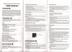
...............37 1. Overall
1.1 Features:
Optical Power Meter
2.WaveID-Autowavelengthidentification&switching
3.FrequencyID---Autofrequencyidentification
4.2typesofbacklightmodes,manualoroutsidelightintensity,
whichindicatedbyLEDlightredorblue color.
5;Jntelligentbacklight
6.1000recordsstorageordownloadviaUSBcabJe
7.USBcommunicationportforsavedtestingrecordsdownload
8. Referencepowerlevelcanbesetupandstored
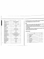
9. Userself-calibratingfunction 10.Auto-offfunction 11.Upto200hrsbatterylife 12.Specifications Type
Calibration Wavelength (nm)
I
A
Detector type
Measurement Range (dBm)
Uncertainty (dB)
linearity (dB)
Display resolution(dB)
Frequency 10 (Hz)
Wave 10 (nm)
InGaAs
-70-+6
I
±0.15 (3.5%)
-50-+26
±0.02
0.01
270, 330, lK, 2K
1310, 1490, 1550, 1625
Date Storage Capacity
1000
Communication Port
USB
Standard Connector
FC 12.5mm universal
Op1ional Optical Connector
FCISCIST Interchangeable/2.5mm universal
Optional Optical Connector
LCIFC/SC/ST Interchangeable
Alkaline battery
Power Adapter(V)
Battery Operating time (h)
S'AA, 1.5V
8.4
200 without backlight
Operation Temperature("'C)
-10
+60
Storage Temperature("'C)
-25
+70
Dimension(mm)
3
C
8501130011310114901155011625
Weight(g)
175'90'44.5
231
Remark: Battery operating time is based on the condition of the power off the backlight. I
power on the backlight continuously, the operation time will be shorter.
Notes:
1. Calibration Wavelength: Specified standard operating wavelength range in which th
Power Meter can work properly under certain technical specifications.
2. Power Measurement Range: The maximum and minimum range in which the Power Mete
can work properly.
3. Uncertainty: Difference between two measurement results that were tested by Powe
Meter and another Standard Power Meter respectively.
13.Standard packages
,...---
No.
f
1
f----
name
Optical Power Meter
2
User Manual
3
USB cable
4
CD
5
1.5V AA battery
6
Power Supply Unit
r-38
Cotton Swabs
Carry 8ag
qly
1
1
1
1
3
1
1
1
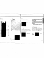
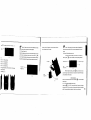
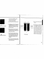
padFunctions:
@) PowerKey .
!
(2)0 WavelenglhSelectionlWavelenglhiaenlliy
Short press this key to switch the wavelength and display it on the
ON/OFF the instrument
Power Saving setting: the unit will automati- .
cally shut off after 15 minutes idle time, j
whatever in the condition of battery power
supply or AC power supply. Once choose
this setting, the "auto-off' will display on the
left bottom of the screen. This power saving
is the default setting, once open the power
meter, will enter into this mode. Short press
the power key to off auto power saving
mode.
top left of the LCD screen, 1310nm is the default wavelength
Calibrated wavelength
(9)
(8)
@
backlight control(two mode of back light control, press this
"LDR" the intelligent backlight control mode. Power meter will off/on the
backside in t1Ssecond based on the oUlside light condition, and this is
the default mode
.1
(10) (3)
key to choose one mode):
Sack light control key mode. Press@ 10 on/off the back light
(4)
8
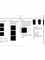
Saving/data-view key. Data-saving, THIS TYPE OPTICAL POWER METER can saving not Press the
2 seconds, enter into wavelength auto
identify. on the upper right of screen have "AU" , and also long
less than 1000 data. press8, the screen will display the data saving No, tip saving the data, doUbei press the8 confirm the saving. press this key to quite this function.
(7)
(6)
-- Wavelength auto-identify
(5)
Current
.saving
-
data saving No.
data{wilvdengtb,
output
(4)
2-1
Power
6
ew. long press
short press
8
S
.~ ",8""... enter into the data view
can view the data.
0008
Press this key to switch between the absolute measurement{dBm)
"1
To store the current power value as the reference value which wIlt be and relative measurement(dB) and xW of the optical power.
l.!,
displayed on the top right of the LCD screen, at the same time the
mW.dBm conversion: 10
11
"Ref" also display on the right top. It will compare the current power
"I with the reference power and show the relative power value in dB. log(mW)~(dBm)
mW.uW.nW conversion: 1mW=103uW=106nW
_ _'- _ _
(Green)
~(red)
The relationship between relative value(dB), absolute value(dBm), and Ref value: relative value= ! absolute value
I • I Ref I (9) "LOR" Intelligent backlight controller
dllm
In the intelligent backlight control mode, the controller wlll
automatically adjust the backlight with the outside light, which to
ive value
save the power.
(10)Screen Display the data and the instrument working mode. O<JOI
(8) "Bll SET"backllght Indicator
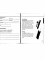
3. Operation Instruction and Notes
Indicate backlight control mode. Green light indicate that
2.1 Powering the Optical Power Meter
"LOR" intelligent backlight control mode, Red light indicate that
The optical power meter can be either battery powered or AC
key"""ntrol mode
elete. When view the data,
adaptor powered, giving total flexibility for most testing sit.s and
situations
Delete/Gancel Key"
press~to delete the
2.1.1 M battelY
xW
the saving. When in the saving mode, press ~to
~
current data saving.
8
"~. """"-~'''~'~-.
I
"'!1f
ldicate
==t
Notice: Make SUre that you insert the batteries with their
positive and negative connectors correctly aligned.
II
When use the AC adaptor, connect the power plug
~
piC, and Insert to the AC socket.
at this time on the left top of the screen, there will be a
Ie:
~
70%
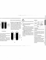
101l"A, electricity
3-3)0 When the battelY In the power
meter,
Notice: Please use only the power supply unit supplied with
moots.
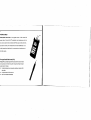
3.2 Power On the optical power meter
When the baltelY Is used out. can use the power supply unit, and
3-1
~
O'
the tester, use other kind of PSU may cause damage for the instru
'.
3.1.2 Power Supply Unit
as
r-J'"(
First of all insert the battery or the PSU, do not have any
and stil have enough
laser In, press
@
to open the tester, 6·5 Is the opening Interface
electricity, the tester will choose AC power supply as the priOrity.
~ 40% - 70% electricity
clIlllmrted wavelength
~ 30% - 40% electricity
~ 20%
dem
30% electricity"
It enough electricity, left less than 20%, the power
)rced power off
Power
ACpower
mod~(Allto·ofl)
supply Sign
>-5
When the tester Is standby, press
the battelY, $-2
@
key can cancel or chaos
auto-off function.!f auto-off fucnlton are choosed, the "Auto·off"wlll display
3-3
Power
SupplyUnil
on the left bottom of the screen.
6.3Backllghtsetting
After open the optical power meter, long press
34
@' choose backlight
control mode.
3.3.1 "LDR" Intelligent backlight control mode
Long press
@ , "BIL'SET" is green (6·6),after 10 seconds, the green
Indicate off, the LDR the controller will automatically adjust the baCklight
within 15 seconds with the outside light, which to save the power.
3·2
10
--==1
3.4.1 Take off the dust cap, connect with the patch cord.
indicator(Green)
a~
lJ
(dBm) and relative measurement(dB) and xW of the
Notice: Make sure the connector and the end~face of the
patch cord is clean, and take notice on the type of the patch cord,
3.4.3 unit switch
press8to switch between the absolute easurement
.
optical power.(6-9)
3.4.4 Relative value measurement
Each wavelength can set the Ref value, Press
8 '
set the current value as the ref value, and automati
cally calculate out the relative value. (Right top of the
screen display the "ref' and setting dBm value 6-10)
make sure the correct patch cord are connected.
~-Relative
Relatj ... e value setting
3.4.2 Select the wavelength
e key control backlight mode.
Short press
, select the calibrated wavelength, notice that if
, "BIL SET" indicator turns to red(3·7), enter into key
the selected wavelength are not the same with the laser source
mode, after 1 0 seconds the indicator off, short press
wavelength. that will cause the error of the measurement value.
FF the backlight.
value setting
3-10
There are 6 calibration wavelength for selection.
dB
(3-8)
3.4.5 Data processing
Data saving and deleting. The power meter have
1060 data saving memory. When do the output
power measurement, press
Calibration wavelength
Indicator{red)
~
, at the right top of
the screen will display the data saving No. eg:
"OOOS" (6-11), hint that if the data save or not, double
press
~ confirm the saving,
GJ
cancel saving.
3-8
·7
3·9
12
Data saving No.
3.5 Data Communication
a~
jl
Note: Before proceed the data communication
make sure the driver and application software are
3·11
W
& delete. Long press
{3 , can view the
cord, the screen will display the last saving
art press
s
3.5.1 Open the software
(3 , can view the data from the
rd.( 3-12) Press
{3
to delete the record,
{3 exit the data view.
;
installed successfully (Details of installation please
refer to chapter 5)
Double click
ill icon to open the software, user can
choose the language on request (Chinese or English).
shown as figure 3-13
~,~'.~
,..,.....""Iit,r'~--,H_' ~S\ooIljot_;
~
!3t ...ct. ....J
Ix ....ct.~
"0;:
·r·'=-·l-',;";';;';--Co;';'i,';;;---;-i.,;"·p
El
.,..,
1111
III
1__
ffi""'~dives
I
$"IYt'Il/Cl>1l.OM~
I!l~_"""",_
~.JI_"'
ffj·§IreATA/Aft4'ltJ'.riMn
""$-
;
,b_
/'
rfr·\JMte<ll\'ldM~t'ri:es
!i! § Mri«$
i!I"-_
m1J,OOJef~
Et;!fPtris{Cr»I&U"T)
~
!
-""(<<>'"
ill
ru
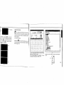
Connect Optical power meier with computer via USB
cable, turns on the power meter.
From the Device Manager: "Port (COM<P) , We can
see that power meter port is "COM4".(3-14) il
3-14 Therefore. choose "COM4" port shown as below figure (3-15) COM!
COM3
COM4
LPTI
Refresh
--...--..
3·12
~~---------
3·15
14
· "Connect" as shown in below figure 3-16, will
successful connection window shown as
k "OK" to finish the connection, the unit can
nicated with computer properly.
3.5.2 Data edit
Firstiy, Input the following basic information as shown on figure 3-18. t-ti~_:~.~-~:'j.jj- ~
, .... ItooI ....-;..
~:-
[iJ
%/:6M41i' (.....
3-16
c~
1 nt Optrat01:
Instrument Seriu Number:
Compe.ny:
Instrurunt Nodil:
H'ohs:
Connection cOI'l'\P~ete:
OK
I
iho~~~I';~':~il ~
-\iiii"""~
I
:t.oo._1....;l ..... (~_~~ .. "'
_ _ _ iii.'-·'"
....H_I;;,;,;;.·· .
~~r';;'H-~";;"'·'-'r--
~
11Cw-.... 1
11<""'011:11
-"kit~-- i" k;;;---T]
.~~:~~-'~'j·~~~~~Jilid=.~
,on ..... ,
e;..,_
~~-~~----~
1<o_!!oo"'a ........
~'- .. --
hoo_Wol
~----
l~
f"--
.
T
3-18
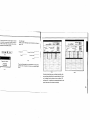
Then click "Upload data·, the saved data in the unit will be
uploaded into computer and shown as on below figure
(3-19).
3-17
3-20
Data edit at data display are,a, including data delete, data
save and data priting.Select the required data,click "delete
one" to delete it from the sheet, as shown on figure 3-20
and figure 3-21, in addition,the corresponding data from the
power meter also will be cleared accordingly.
16
.... ~
~:
;;-
--'~J.•• o1,-,~
:';;;-'
__ .....,r~~-~'--·"-
"G:ldllil
Delete 011 the data
ilK::]
C"""el
3-22
Click "Save" pop up a window shown as figure 3-23,
3-21
k "OK" to delete all data, also will clear all
,ta from the unit.
•
"'=-' -"'_
...
!OAITE$~
Io-P-I"I
:3
:3
input the file name, choose the save path and press
"ok" for storage. File will be with EXCEL format and
lete all"pop up a window shown as figure
~!..
will pop up testing report automatically shown as
figure 3-24.
3-23
3-24
Click[j;Uon the software ,you can pnnt testing report
directly, you can also print the testing report from Excel.
18
ction setting on the unit
elion setting mode to switch the interface
(3)8ack to factory mode
There are there items can be set on the unit:
(1) Optical Power Calibration
on figure 3-25 and figure 3-26:
Power calib:r:a:tion:
~"'"C~ib~ ..i~
o
[.JJ,
,
Reset
3-29 3-27 ~
3-25
"~-::at
11"_';;;'_'
•
Enable light source be Under "Wave ID" operation mode:
press
0
of light source to emerge light output from
@
light source.Hold down
default setting(factory mode setting).
will be enter into Wave ID mode, also "--AU"wili be shown on
3_5.4 Close software
the upper right of LCD for a Indication.
Click exit,pop up a window shown as below
tion" , users can recalibrate the optical power by them
(figure 3-30):
•
for few seconds,light source
Enable power meter be under "Wave ID"operation mode: Hold down
selves. ffi
for few seconds, power meter will be enter into Wave ID mode, also "--AU"will be shown on the
(2) Time setting
Ar. you SlJre you
I~
Sot
J
r
WUlt
to qui t th. system?
OK:J ~.
upper right of LCD for a indication.
• Once the 10 information is changed from light source
(press
~
~
Connect power meter with its same serials light source.
Click "Reset",the unit will be back to
Input the corresponding optical power and click calibra
I§(~'I
'.i'.',
•
3-28
3-30
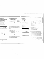
3.6 Wavelength Automatic Identification
Input the corresponding date and time, and then click
"Set" to modify the time and date accordingly.
ffi to change wavelength), after 3 to 5 seconds
later, the detected information on optical power meter also
will be changed automatically according to light source.
Please refer to below figure(3-31) for easy understanding.
• Exit Wave ID mode: Hold down
ffi
again to exit Wave ID
mode from power meter and hold down
Wave ID mode from light source.
3-26
@
again to exit
20
•
•
l<i>'
a Note: Connect power meter with its same serials light source .
11
Frequency ID and wave ID cannot be operated at the same for very short \ I
To avoid risk of serious eye damage, please do not look into Output frequency from optical light source: Press
emerge light from the unit, press
@
0
to
second, light Source will output frequencies of 270Hz,
l(
330Hz, 1KHz, 2KHz accordingly, which will be shown on
time. the optical port of laser source at any time. 3.8 Power off
the upper right of the LCD in light source. In the mean
Automatic power off: When auto-off function is
time, the power meter will detect the corresponding
activated, the unit will turn itself off automatically after
frequency automatically from light source. Please refer
lighlSourca
PowarMeler 3·31 10minutes idle time, whatever the power supply is with alka
to below figurll (6-32) for better understanding:
line batteries or is with power supply adaptor directly.
Manual power off: Under any operation mode, hold
3.7 Frequency detection
down
@
for a few second,. to turn the unit off.
Note: With either power off operation, the unit will store the
When use tone detection function, following require last calibration wavelength and backlight control mode auto
have to be taken into account: PEA: Tone detection will be effective only with mea ent range between +6--40dBm.
270Hz
matically, which will be the default setting when user turns
330""
unit on next time.
lKH"
5.1 Always keep the connector ports of your power
meter are clean.
5.2 Do not use bad quality optical fiber
connectors/adaptors, otherWise, it will damage the
interface of detector that will greatly affect the perfor
mance of the unit
5.3 Try to use only the adaptor supplied.
5.4 Once not in use, make sure dust-proof cap is
5.5 Carefully plug in/out for fiber connectors/adapters
-20dB, because the
ed frequency will be unstable when the power is weak.
to act tone detection on Power Meter?
5 General Maintenance
placed properly over the optical ports.
PEC: Tone detection can be worked only with mea
nent range between +26 -
4 Troubleshooting
LightSou(ce
PowarMeter
1\ to avoid scratches on the port of the power meter.
5.6 Keep regular cleanings on optical port of power
meter, please clean with colton swabs supplied using
3-32
alcohol properly.
22
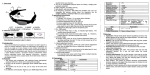
1. Overall
1.1 Features :
• Wave ID information can be transmItted when used with Optical Power Meter. • Tone generation, 270HZ.330HZ,1KHZ,2KHZ
• Output power can be adjustable
• Output power value is shown on LCD display
• Intelligent backlight control (light intenSity can be adjusted properly according to ambient light. which greatly reduced power consumption) Optical Light Source
• AA alkaline and AC adapter for power supply
• Low battery indication
24
'-,
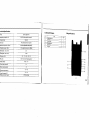
echnicalSpecifications
1.3.StandardPackages
--
2.KeypadFunctions
Opticnl Light Source Name No,
1310/1550 (others specify on requests) Operating wavelength (nm) Applicable fiber SM,MM FP-LD(others specify on requests) Laser type ·5 (can be adjustable, others specify)
Maximum Output Power (<IBm) Adjustable step size (<IBm) 1
2
Name
Opticall!ght Source
User ManuaJ
3
1.5V AA battery
4
Power $vpply Unit
S
Cotton Swabs
~ CarryBag
QIY
1
1
3
1
1
1
<0.5 (adjustable between ·S-12dBm) Stability(<IB, 15min, 20"(:) ±O.l --
±M5 Stability(<IB, 30min, 20"(:) Modulation (Hz) Fiber Port CW,
270, 330, IK, 2K FCfPC or FC,SC,ST interchangeable
3°AA, 1.5V
(I)
Power Supply Adaptor(V) 8.4
(2)
Battery Operating time(b) 45
Alkaline Battery Operation Temperatur.eCl Storage Temperalure("C)
Outline sizc (mm) /weight
(3)
-10-+60
-25-+70
175·90·U.5125~"
2-1
26
Power Key
the instrument
wing setting: the unit will automatically shut off
ninutes idle time, Once choose this setting, the
will display on the left bottom of the screen.
er saving is the default setting, once open the
(6) @ Modulation adjustment/wavelength identifying
Laser on. After on the tester, firstfy press@, to laser on
the light source. Short pmss @ shift the frequency.
(270,330, 1K,2KHz) OHz means do not Loading
frequency. Long press enter into/exit the wavelength
identify mode, on the right top of the screen "--AU"display
eter, will enter into this mode.
when enter into the wavelength Identify mode.
Wavelength Selection
the tester, first press
to laser on, then
to select the wavelength and display the
tavelength on the left top of the screen.
I)
CD
backlight control. JW3116 have two type of
t control, pmss @to choose one mode:
e intelligent backlight control mode. Power
II off/on the backlight within 15second based on
de light condition, and this is the default mode.
lt control key mode. Press @
to on/offthe
It
IRated power.
lutput power
'Down the rated power
I the rated output power
3.1 Ways of power supply
JW3116 can be either battery powered or AC
adaptor powered, giving total flexibility for most
testing sites and situations
0
backlight in the key control mode.
(9) "LOR" Intelligent backlight controller
In the intelligent backlight control mode, the controller
will automatically adjust the backlight with the outside
light, which to save the power.
(10)Screen Display the data and the instrument working mode. ~
~
I;;]
CJ
n
3.1.1 AA battery
When use AA battery,
(7)
output power up Up the output power (8) "BIL SET"backlight indicator
Indicate the backlight control mode, when the indicator
green, which means "LOR" in the Intelligent back light
control mode, when the indicator red, which means the
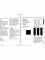
There are 5 Grades for the battery power Indication:
3. Operation Instruction
I] will display on the
left 70%
~
100% electriCity
left 40%
~
70% electricity
left 30%
~
40% electricity
left 20%
~
30% electricity..
not enough electricity, left less than 20%,
the power meter will be forced power off.Fit the
battery, refer to below figum 3-2
left top of the screen,3-1 ..
Battery Power indicate
3-1
3-2
Press the clip fastener on the battery compart
ment cover down. Remove the battery compart
ment cover, remove all three batteries making a
note of their positive and negative connector
orientation. The negative battery connector
should be against the spring. Insert 3 new 1.5W
AA battery. Refit the battery compartment cover.
The clip fastener should click shut.
28
~
cr
Notice: Make sure that you insert the
,s with their positive and negative connec
rrectly aligned.
Notice: Please use only the power supply
unit supplied with the tester, use other kind of PSU
After open the optical power meter, long press
@
choose backlight control mode.
3.3.1 "LDR" Intelligent backlight control mode'
may Cause damage for the instruments.
@ , "BIL SET" is green (6-6),after 10
ower Supply Unit
3.2 Power on the laser source
Long press
:he battery is used out, can use the power
First of all insert the battery or the PSU, press @on
seconds, the green indicate off, the LDR the controller will
the tester, at this time the laser are still off, the opening
automatically adjust the backlight within 15 seconds with
displaying as 3-5
the outside light, which to save the power
unit, and at this time on the left top of the
I,
there will be a " ' " (3-3). When the
in the power meter, and still have enough
lity, the tester will choose AC power supply
Electricity
priority.
Laser off
Selected wavelength
Raledpl',lwer
I--~~-
Power
rnode(Au!o-oft)
Power
indicator(Green)
3-5
When the tester is standby, press
®
key Can cancel or
choos auto-off function .If auto-off fucniton are choosed,
the "Auto-off" will display on the left bottom ofthe screen.
34
3.3 Backlight Setting
3-3
3-6
use the AC adaptor, connect the power
I
pic, and insert to the AC socket.
30
~e
the key control backlight mode
@ . "Bll SET" indicator turns to red(6-7).
ey control backlight mode. after 10 seconds
.or off, short press
@
can ONIOFF the
~ Notice:
C-
0 .
Press
select the output wavelength, display at
the top of the screen. 3-10
Make sure the connector and the
end-face of the patch cord is clean. and take notice
on the type of the patch cord. make sure the correct
patch cord are connected .
3.4.2 laser on the light source.
When open JW3116.Jhe laser source still laser off.
only after press
Laser off (1) or@ can laser on the diode
laser on(output wavelength
1310nm. rated output
power-5.00dBm, 270Hz
frequencyOHz means do not
load the frequency
(3-8 & 3-9)
1----- Indicator(red)
3-9 press
00
Output wavelength
3·10
3.4.4 Output power to laser on the diode
Every selected wavelength can adjust the output power within the range (-5 - -12dBm). and a/so can load with the output frequency. ~ Notice: To avoid risk of serious eye damage.
03-7
3.4 Output Power
Laser off
laser on(output wave
length 1310nm, rated
output power-5.00dBm.
OHz means do not load the
frequency
Do not look into the interraces at any time.
Press (!Vto down the output power. while @to load
the output frequency. (3-11 - 3-13)
3.4.3 Select the wavelength
otice: Preheating is normally required to
stable output power for the laser source.
3-8 press0 to laser on the diode
less than 15 minutes would be okay.
pen the dust cap, connect with the patch
3-11
I!I
-----~.--------'-"'.--'-.--
32
For the same principle, press0to up the output power, while to load the output frequency. 3.5 Wavelength Automatic Identification
• Connect light source with its same serials power meter.
)resS down the output power
• Enable light source be Under "Wave ID" operation mode:
press CD or@oflightsourceto laser on JW2116, Hold
down @ for few seconds, light source will be enter into
Wave ID mode. also "--AU" will be shown on the upper
right of LCD for a indication.
• Enable power meter be under "Wave ID"operation mode:
Hold down CD for few seconds, power meter will be
enter into Wave ID mode, also "-AU"will be shown on the
upper right of LCD for a Indication.
~-----)~
13lOnm(xxdBm
1550nm(xxdBnv
ress@to load the frequency
Connect light source with lis same serials
power meter
•
Output frequency from optical light source:
Press
CD
or@toemergelightfromthe
unit, press @
for very short second, light
source will output frequencies of 270Hz.
330Hz. 1KHz. 2KHz accordingly, which will be
shown on the upper right of the LCD In light
Light source
Power Meter
3·14
• Once the ID information is changed from light source
(press CD to change wavelength), after 3 to 5 seconds
later, the detected information on optical power meter
also will be changed automatically according to light
source. Please refer to below figure(3-14) for easy
understanding.
•
source. In the mean time, the power meter
will detect the corresponding frequency auto
matically from light source. Please refer to
below figure (3-15) for better understanding:
3.6 Frequency detection
• Exit Wave ID mode: Hold down CD again to exit Wave ID
mode from power meter and hold down @ again to exit
Wave ID mode from light source.
34
-
3.7 Power Off
Automatic power off: When auto-off function is
4.Troubleshooting.
after 10minutes idle time, whatever the power supply
is with alkaline batteries 6r is with power supply
adaptor directly.
Manual power off: Under any operation mode, hold
down@ for a few seconds to turn the unit off.
Faint display on the LCD
$olutron
Possible eause
Problems
activated, the unit will turn itself off automatically
3.
4.
screen
f'"(!j'l
Power is off
the battery power 1$
3.
Press \.!::!) key.
too low
4.
Change the batteries When on the laser source, the output power is not
After 15 min. preheat stable Note: With either power off operation, the unit will
store the last calibration wavelength and backlight
control mode automatically, which will be the default
setting when user turns unit on next time.
Power Meter
Source
5.GeneralMaintenance
5.1 Always keep the connector ports of your laser source are clean.
3-1:$15
5.2 Try to use only the adaptor supplied. 5'.3 Once not in use, make sure dust-proof cap is placed properly over the optical_ports. 5.4 Carefully plug in/out for fiber connectors/adapters to avoid scratches on the port v of the power meter.
ole: Frequency
5.5 Keep regular cleanings on optical port of power meter, please clean with cotton swabs supplied using
to and wave to cannot be
alcohol properly.
,d at the same time.
d risk of serious eye damage, please do not
the optical port of laser source at any time.
36
----------
I-~_ _-----~---
lnty and Service
on: Repair the instruments in the field is prohibited<
18 months warranty for Fiber Optic Test & Measurement
A warranty registratlon card is included with the original shipment of
equipment Please take a few mome,nts to fill out the card and mail or fax
It to OUR COMPANY to ensure proper initiation of your warrarrty lerm,
lments
mties that each of Instruments will be free from defects in
To return a defective product for warranty coverage, contact OUR
~al and wcrkmanship for 18 months< This warrarrty covers the
COMPANY for a written authorizalion. Failure to properly protect the
lal user only and is not transferable. Should the device fail al any
product during shipping may avoid this warranty,
during Ihis warranty period, OUR COMPANY will, at its sole
OUR COMPANY will pay retum Iransportation for products repaired or
etlon, replace, repair or refund the purchase price of the product<
replace in warranty period. Before making a repair not covered the
warranty is limited to defects in workmanship and materials and
warranty, OUR COMPANY will estimale cost and obtain aulhorlzation,
nol cover damage from accident, acts of God, neglect,
Ihen invoice for repair and return transportallon, OUR COMPANY
minatlon, misuse or abnormal conditions of operation or
resel'V1iils Ihe right to charge for all testing and shipping costs Incurred, if
An important message from
OUR COMPANY
OUR COMPANY guarantees that any information you supply will remain
confidential.
By returning this card, you will automatically be notified about updates, modifi
cations, and recalibration.
tesl results determine thallhe device is withoul defect,
ling.
stablish original ownership and provide date of purchase, please
,Jete and relUm the registration card to OUR COMPANY, This
onty card will not go into effect until the warranty registration has
1 received by OUR COMPANY,
38
________'..-c-_
..
-~.~-
rranty registration card rial Number:
del
------------------
Date of Purchase: _______________________ Number:'--__________ Company Name:
mpanyAddress: ______________________________
L: _____________
FAX:
ail:________________________________
OICE YOUR OPINION OpticalFiberldentifier
Optical Fiber Identifier can quickly identify the direction
of transmitted fiber and display the relative core power
without any damages to the bended fiber. When the traffic
is present, the intermittently audible tone is activated. The
optical fiber identifier also recognize the modulation
Iike,270Hz,lkHz and 2kHz .When they are used to detect
the frequency, the continuously audible tone is activated.
There are four adapter heads available: 00.25, 00.9, 02.0
and 03.0. The optical fiber identifier is powered by a 9V
alkaline battery .
you have any comments on the quality of this OUR MPANY product or the service from OUR COMPANY?
FiberRanger
Optical Fiber Ranger is the most portable test instrument
in the industry. It adopts the OTDR technical principles and
integrates the powerful analysis software, which enables
the fiber ranger detect fiber faults location more accurate
and easy.
40
PONPowerMeler
PON Optical Power Meter is an upgraded version of old version PON
power meter. It alms at the F1Tx application and maintenance which not
only can be used to test and estimate the PON signals at the same time,
but also the normal power measurement and fault identification. It is a
useful, essential and ideal tool for the construction and maintenance 01
the PON projeds.
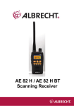
Pen-typeVisuaIFaullLocalor(VFL)
Pentype VFL
is specially designed ror field personnel who need an efficient
and economical tool for fiber tracing, fiber routing and continuity checking in
optical network. It includes:
•
Finding the breakpOint, poor connections. bending or cracking in fiber
optic cables.
•
Finding the faults of OTDR dead zone
•
End-la-end visual fiber identification
,/
N
o
N