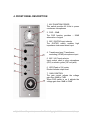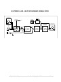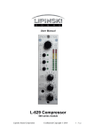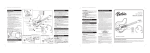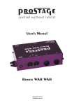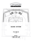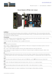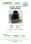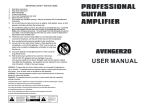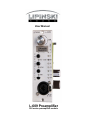
1
User Manual
L-609 Preamplifier
500 series preamplifier module
PRECAUTIONS AND SAFETY CONSIDERATIONS
We designed our product with maximum care in accordance with international
safety standards.
CAUTION
Always follow the basic precautions listed below to avoid the possibility of
physical injury to you or others, or damage to the device or other property.
These precautions include, but are not limited to, the following:
●
Read setup instructions provided by us,
●
Follow these instructions,
●
Always insure that the preamplifier is properly grounded,
●
Only use accessories manufactured, specified or recommended by
Lipinski,
●
Do not use un-authorized main cables,
●
All servicing must be performed by our qualified personnel,
●
Do not expose this product to moisture, rain or water or direct sunlight,
●
Insure adequate air circulation around your preamplifier,
●
Power sources — Connect this unit only to power sources specified in the
Operating Instructions, and as marked on the unit,
●
To avoid damage to your speakers and other playback equipment, turn off
power to all related components before making any connections,
●
Heat — Do not use this unit near heat sources, including heating vents,
stoves, or other appliances that generate heat. It should not be placed in
temperatures less than 40°F or higher than 95°F.
2
CONTENTS
1. INTRODUCTION ...................................................................................... 4
2. UNPACKING ............................................................................................ 4
3. FEATURES .............................................................................................. 5
4. FRONT PANEL DESCRIPTION ............................................................... 6
5. QUICK GUIDE TO USING THE L-609 PREAMPLIFIER.......................... 7
6. MAIN BOARD VIEW ................................................................................ 8
7. PRODUCT SPECIFICATION ................................................................... 8
8. LIPINSKI L-609 – BLOCK DIAGRAM, SIGNAL PATH ............................. 9
Lipinski Sound Corporation|
Confidential Copyright © 2008
3|Page
“Thank you for putting your trust with Lipinski. We understand how convoluted the
market place may be, and how difficult it is to come to a good decision in regard to
sound quality. We appreciate your research and hope you enjoy your purchase.”
Many Thanks,
Lukas A. Lipinski
Executive Director
1. INTRODUCTION
You have selected Lipinski equipment which hails from thirty years of recording
experience of Mr. Andrew Lipinski and his devotion to state-of–the-art sound.
To achieve this sound in the L-609 Pre-amplifier, we eliminated all capacitors and
Integrated Circuits from the signal path and created our own, Lipinski Square –
patented discrete class A technology. We also created transformer-like circuitry
emulating an amorphous core transformer, albeit without unwanted, odd harmonic
distortion.
2. UNPACKING
Our product is carefully packed by us to maximize safety in transport. We advise
that you unpack it on a soft, thick surface (carpet, fitted carpet, blanket etc)
It helps to save all original packing materials and use them when you move the
product.
Lipinski Sound Corporation|
Confidential Copyright © 2010
4|Page
3. FEATURES
•
•
•
•
•
•
•
•
All discrete, class A patented circuitry
No capacitors in the signal path
No IC’s in the signal path
Microphone XLR or instrument DI high impedance ¼ inch input
Precision rotary gain control
8 position LED Peak / VU meter, switchable inside
48 Volt phantom power
Resistor-less, -20dB PAD, which skips one stage of amplification to maintain
signal quality
• Transformerless / Transformer input mode - proprietary circuit emulating
amorphous core transformer, eliminates unwanted distortion
• Minimal internal signal wiring
• Gain control is implemented in negative feedback loop,
therefore it does not degrade dynamics
Lipinski Sound Corporation|
Confidential Copyright © 2010
5|Page
4. FRONT PANEL DESCRIPTION
1. 48V PHANTOM POWER
This switch provides 48 Volts to power
condenser microphones
2. PAD – 20dB
The PAD function provides – 20dB
attenuation of signal
3. MIC / GUITAR input selector
The GUITAR switch enables
impedance instrument direct input
high
4. Transformer-less / Transformeremulating (XFMR) microphone input
5. MIC / HI-Z input selector
Input socket used to plug microphone
(XLR) or electric guitar (1/4 inch jack)
6. LED (Peak or VU) meter
Diodes indicate output level
7. GAIN CONTROL
The gain control adjusts the voltage
gain from 38dB to 73dB
When PAD switch is on, it adjusts the
voltage gain from 18dB to 53dB
Lipinski Sound Corporation|
Confidential Copyright © 2010
6|Page
5. QUICK GUIDE TO USING THE L-609 PREAMPLIFIER
Mounting
The L-609 Preamplifier requires a 500 Series rack.
1. First, turn off and unplug your rack frame. Make sure the slot you intend to
use is clean and free of debris
2. Firmly and evenly push the L-609 Preamplifier into place until it is well
situated in the card slot
3. Mount the L-609 front panel with two screws, to the 500 series rack
Note: The screws are tight-fitting. Make sure to not cross the thread
4. Plug your 500 series rack back into the AC source, and power-up your rack
Set up
1. Turn the gain fully counter-clockwise and check that phantom power is off.
2. Using shielded, low capacitance microphone cable, connect a microphone
to the preamplifier and then turn on the phantom power switch if required.
When sending a signal to a recorder that has fixed input levels, simply
increase the gain until the optimum recording level is reached.
3. Careful! Turning the phantom power switch on or off, or the main power
switch on or off can produce a large amplitude spike in the line output.
Protect your ears, speakers, and equipment by being careful while the
L-609 Preamplifier output is connected to another piece of equipment.
4. Enjoy the sound of Lipinski.
Lipinski Sound Corporation|
Confidential Copyright © 2010
7|Page
6. MAIN BOARD VIEW
Peak / VU switch: When VU meter is on, LED indicator on the front panel shows
a subjective level of loudness. Otherwise instantaneous output level is measured.
7. PRODUCT SPECIFICATION
Potentiometer gain range
Minimum gain (with –20 dB Pad)
Maximum gain
Dynamic range (curve A)
Distortion (0 dB out)
Distortion (+12 dB out)
Maximum low distortion output
Mic input impedance
DI input impedance
Power supply current
Operating voltages
Lipinski Sound Corporation|
35dB
18dB
73dB
126dB
0.008%
0.016%
+22dB
6.8kΩ
220kΩ
58mA
+/-16V
Confidential Copyright © 2010
8|Page
8. LIPINSKI L-609 – BLOCK DIAGRAM, SIGNAL PATH
500 Series Rack
Peak / VU
MIC IN
LED Meter
PHANTOM
+48V
GAIN CONTROL
MIC IN
XFMR
MIC / GUIT
20dB
PAD -20dB
BALANCING
CIRCUIT
500 Series Rack
OUT
0 - 35dB
HI-Z IN
Lipinski Sound Corporation|
Confidential Copyright © 2010
9|Page
We wish you fantastic, unforgettable, moments of audio performance.
The Lipinski Team
Lipinski Sound Corporation|
Confidential Copyright © 2010
10 | P a g e