1
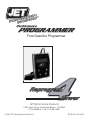
Performance
PROGRAMMER
Ford Gasoline Programmer
4
Reprogram
Power
JET Performance Products
17491 Apex Circle, Huntington Beach, CA 92647
(714) 848-5515 • Fax: (714) 847-6290
© 2007 JET Performance Products
JET P/N 15-300 02/07
INSTALLATION INSTRUCTIONS OVERVIEW
Your vehicle has an onboard computer that controls the engine and transmission. The
JET programmer reprograms your factory computer according to your specifications
with JET Performance Products Tuning.
To reprogram your vehicle’s computer, simply plug the programmer cable into the
vehicle’s diagnostic connector, located under the dash panel on the driver’s side. Set
the parking brake. Next, turn the ignition key to RUN but do not start the engine. It will
then identify your vehicle and ask a series of questions on its LCD screen.
When completed, turn the key to OFF and disconnect the cable from the diagnostic
connector. Now you’re “Engineered for Power”.
JET Performance Product’s tuning can be stored in only one vehicle. When you install
JET Performance Product’s tuning program into your vehicle, the programmer reads
and stores your vehicle’s factory programming. You can use the Programmer to restore
your stock programming if it should ever become necessary.
You may also reconnect your programmer at any time to modify the programming.
Simply reconnect the JET Performance programmer, answer the necessary questions,
and program your vehicle.
PROGRAMMING INSTRUCTIONS
1. Locate the Data Link Connector (DLC) under the driver’s side of the dash
panel.
2. Plug the Programmer cable into the DLC. Make sure the cable is plugged in
completely to ensure a good connection.
3. Set the parking brake to turn off the DRLs (DayLight Running Lamps)
IMPORTANT:
•
DO NOT LEAVE THE VEHICLE WHILE PROGRAMMING IS IN
PROGRESS.
•
MAKE SURE THE VEHICLE BATTERY IS FULLY CHARGED
BEFORE PROGRAMMING.
•
IF THE VEHICLE HAS BEEN PROGRAMMED USING ANOTHER
MANUFACTURERS PROGRAMMER, YOU MUST RETURN THE
VEHICLE TO STOCK PROGRAMMING BEFORE USING THE JET
PROGRAMMER.
•
DO NOT DISTURB OR UNPLUG THE CABLE UNTIL THE
PROGRAMMER INSTRUCTS YOU TO DO SO.
•
DO NOT OPERATE ELECTRICAL ACCESSORIES (RADIO,
WINDOWS, WIPERS, ETC.) WHILE PROGRAMMING.
1
•
DO NOT ATTEMPT PROGRAMMING WHILE THE VEHICLE IS
CONNECTED TO A BATTERY CHARGER.
4. The programmer will perform some self tests and then the following will
appear on the screen:
TURN IGNITION ON, PRESS ANY KEY
Now turn the ignition key to the RUN position (BUT DO NOT START
THE VEHICLE).
Note: During the programming process you will be required to cycle
the key on/off several times.
Press any key and the following screen will appear:
Y PROGRAMMING
N SCAN TOOL
5. Press Y to enter Programming Functions and continue with step 6 UNLESS
THE FOLLOWING MESSAGES APPEAR:
•
“NOT FOR THIS VEHICLE” Call JET Customer Service
•
“SOFTWARE NEEDS TO BE UPDATED” Call JET Customer Service
•
RESTORE FACTORY PROGRAMMING This message will appear after you
have previously updated your vehicle with the JET Programmer, answer Y
to this option to return your vehicle to its stock programming answer N to
continue.
Press N to enter Scan Tool Functions (see Page7)
ENGINE TUNING
6. Press Y to install JET EZ Programming (The JET EZ Programming option
is engineered to give you the best performance with the easiest installation.
By selecting this option the JET Performance Programmer will download the
most up to date JET Performance tuning software to increase horsepower
and torque based on your fuel grade selection. In addition, automatic
transmission equipped vehicles will get improved shifting patterns and
increased shift firmness. JET EZ Tuning is a great choice when you want
more power without the need for custom tuning.)
Press N to enter Custom Programming Options (The Custom Programming
option on the JET Performance Programmer allows the user to install JET
Performance Engine tuning based on your fuel grade selection. In addition it
allows the user to select custom changes such as shift points, shift firmness,
2
rev limits, and speed limiters based on tire ratings. If you have changed the
tires or gears on your vehicle and need to correct the speedometer because of
the changes this is the program you will want to use.)
7. Use Arrow keys to scroll through fuel grade options and press Y to select.
Premium fuel is recommended for maximum performance
NOTE: NOT ALL OF THE FOLLOWING OPTIONS ARE AVAILABLE ON ALL VEHICLES
AUTOMATIC TRANSMISSION
8. Press Y if you have an automatic transmission; if you had previously selected
JET EZ Programming, programming will begin immediately see step 23, if you
are doing Custom Programming continue with step 9.
Press N if you have a manual transmission and please note the following; If
you had previously selected JET EZ Programming, programming will begin see
step 23 , If you are doing Custom Programming continue with step 12.
SHIFT POINTS
This allows you to change the Wide Open Throttle (WOT) shift points in
your Automatic transmission for the 1-2 , 2-3 and 3-4 shift points. You
can select to increase or decrease your shift points based on the mile per
hour you want raise or lower the shift points.
NOTE: If you raise your shift points more than 1 or 2 MPH it may be
necessary to raise the RPM Limiter also.
9. Press Y to modify shift points and continue with step 10, Press N to leave shift
points stock and continue with step 11
10. Press Y to modify 1-2 shift, use Arrow keys to move mph up or down and
press Y to select, do the same for 2-3, 3-4 shifts. Press N to leave stock.
SHIFT FIRMNESS
11. Press Y to increase shift firmness, Press N to leave stock.
3
RPM LIMITER
Allows you to change the Factory programmed RPM limiter in your
vehicle by increasing the limit 100 RPM at a time up to the maximum
change of 800 RPM. As noted in the shift point section it may be
necessary to change this if you change the shift points.
12. Press Y to modify RPM limiter and continue with step 13, Press N to leave
RPM limits stock and continue with step 14
13. Press Arrow keys to select RPM limit change and press Y
SPEED LIMITER
This allows you to modify the factory speed limit that is programmed
into your computer. Most vehicles have speed limiters based on the
tires that are installed on the vehicle from the factory. Each tire has a
speed rating that is indicated by a letter designation. For your safety and
the safety of others never exceed the speed rating on your tires or the
posted legal speed limit at any time.
14. Press Y to Modify Speed Limiter and continue with step 15, Press N to leave
stock and continue to step 16
15. Press Arrow Keys to modify speed limiter based on tire rating and press Y
MODIFIED THERMOSTAT Y/N?
This option changes the temperature that the electric fans turn on/off
based on the thermostat that you are using. Included are options for 160
degree, 180 degree and 195 degree thermostats.
16. Press Y to Modify Thermostat temperature and continue with step 17, Press
N to leave stock and continue with step 18.
17. Press Arrow Keys to select correct thermostat temperature and press Y
MODIFIED TIRE SIZE
Use this selection to fix your speedometer and shift points if you have changed your tire size. You can select from 24 to 44 inch tire sizes in half inch increments.
4
NOTE: If your vehicle is equipped with traction control, exceeding 34 inch tire sizes may cause the traction control to not work correctly. In ALL vehicles : Some tire sizes, depending on what gear is in the vehicle, may cause shifting problems even with the correct setting on the programmer. This usually occurs with tires larger than 38 inches.
18. Press Y to correct for tire size changes and continue with step 19, Press N for no
changes and continue with step 20.
19. Press Arrow Keys to select correct tire size and press Y
MODIFIED GEAR RATIO
Use this selection if you have changed the gear ratio in the differential. The
selections include both factory and aftermarket gear ratios that may or may not be available for your vehicle.
20. Press Y to correct for gear ratio changes and continue with step 21, Press N
for no changes and continue with step 22.
21. Press Arrow Keys to select correct gear ratio and press Y
MODIFY CHOICES
22. Press Y to modify choices, Press N if choices are correct and
programming will begin.
23. Programming has begun, do not disturb the cable, key position or
operate anything in the vehicle during the programming process.
NOTE: During programming, vehicles equipped with driver information centers will display various service messages - these are nothing to be concerned about and will go away when programming is complete.
24.
25.
26.
When programming is complete, the Programmer will display Programming Complete, turn the ignition key off and unplug the cable from the Data link connector (DLC).
That’s it! Programming is now complete. Please store your JET Performance Programmer in a safe dry place in its original packaging. You will need the programmer in the future to return your vehicle to stock or modify your settings.
Start the vehicle and verify that the service engine light is NOT on. If your vehicle will not start, see page 6 for details on what to do if your vehicle won’t start after programming.
5
What To Do If Your Vehicle Won’t Start After Programming
In some vehicles with the Passive Anti Theft System (PATS), the programming process will set an error
during the programming process that will prevent the vehicle from starting. Normally if PATS is set the
theft light on the dash will be blinking rapidly. If your vehicle won’t start after programing do the following:
1. Remove the keys from the ignition, all the way out!
2. Put the ignition key in the ignition switch.
3. Turn the key to the run position, but DO NOT start the vehicle.
4. The Theft light on the dash should be blinking rapidly, about three blinks per second.
5. After about 30-45 seconds the Theft light will start to blink slowly and/or go out.
6. After this happens, turn the key off, take the key out of ignition. DON’T TRY TO START THE
VEHICLE YET.
7. Wait 15-20 seconds the insert the key into the ignition.
8. Turn the key to the run position, but DO NOT start the vehicle.
9. The Theft light should now be blinking about 1 blink per second, this indicates that the PATS system has returned to normal mode.
10. If the Theft is blinking normally, about 1 blink per second, you can now start the vehicle. If you still have a rapidly blinking Theft light repeat the procedure.
6
JET SCAN TOOL INSTRUCTIONS
The JET Performance Programmer also functions as a Scan Tool for GM OBDII equipped vehicles. This
allows the user to read and clear any stored data trouble codes in the system and monitor 15 different
outputs from the vehicle.
We have included a list of DTC’s so you will know what code is stored in your vehicle. (This list may or may not include all available codes for all vehicles. Check a factory repair manual for your vehicle.)
Please NOTE: The Scan Tool included in the JET Performance Programmer is included as a convenience only. The interpretation of these codes and there effects are best left to an experienced automotive technician. The JET technical department WILL NOT help you interpret or diagnose any codes, please see your local dealer or technician.
Connecting the JET Programmer Scan Tool:
1. Locate the Data Link Connector (DLC) under the driver’s side of the dash panel.
2. Plug the Programmer cable into the DLC. Make sure the cable is plugged in completely to ensure a good connection.
3. The programmer will perform some self tests and then the following will appear on the screen.
TURN IGNTN ON PRESS ANY KEY
Now turn the ignition key to the RUN position but do not start the vehicle and the following screen will appear:
Y PROGRAMMING
N SCAN TOOL
4. Press N to continue to the Scan Tool section of the JET Programmer and the following screen will appear:
Y DTC READER
N MONITORING
5. Press Y to continue and get DTC’s or N to continue to the real time monitoring.
If you selected Y and there are any DTC’s stored in the system they will be displayed in numerical order, use the arrow keys to scroll through any stored codes. If no DTC’s are found the message on the screen will read NO DTCS stored. You can press any key to continue to the CLEAR DTCS screen. Press N and the programmer will return to the starting screen.
6. If there are DTC’s stored and you want to clear them continue to the CLEAR DTCS Y/N screen and select Y.
If you selected N you now will be in the real time monitoring mode
7.
You will now need to start the vehicle to get the readings. After you have started the vehicle you can access and view the information by using the UP and DOWN arrow keys to get to the next parameter. You can exit the monitoring anytime by pressing the N key. After you are finished with your monitoring session simply turn the vehicle off and unplug the programmer.
7
P00010 A Camshaft Pos Actuator Circuit Bank 1
P0011 A Camshaft Pos Timing - Over Advanced Bank 1
P0012 A Camshaft Pos Timing - Over Retarded Bank 1
P0013 B Camshaft Pos Actuator Circuit Bank 1
P0014 B Camshaft Pos Timing - Over Advanced Bank 1
P0015 B Camshaft Pos Timinng - Oveer Retarded Bank 1
P0020 A Camshaft Pos Actuator Circuuit Bank 2
P0021 A Camshaft Pos Timing - Over Advanced Bank 2
P0022 A Camshaft Pos Timing - Over Retarded Bank 2
P0023 B Camshaft Pos Actuator Circuit Bank 2
P0024 B Camshaft Pos Timing - Over Advanced Bank 2
P0025 B Camshaft Pos Timing - Over Retarded Bank 2
P0030 HO2S Heater Control Circuit Bank 1 Sensor 1
P0031 HO2S Heater Circuit Low Voltage Bank 1 Sensor 1
P0032 HO2S Heater Circuit High Voltage Bank 1 Sensor 1
P0033 Turbo Charger Bypass Valve Ctrl Circuit
P0034 Turbo Charger Bypass Valve Ctrl Circuit Lo
P0035 Turbo Charger Bypass Valve Crl Circuit Hi
P0036 HO2S Heater Control Circuit Bank 1 Sensor 2
P0037 HO2S Heater Circuit Low Voltage Bank 1 Sensor 2
P0038 HO2S Heater Circuit High Voltage Bank 1 Sensor 2
P0042 HO2S Heater Ctrl Circuit Bank 1 Sensor 3
P0043 HO2S Heater Ctrol Circuit Lo Bank 1 Sensor 3
P0044 HO2S Heater Ctrllllll Circuit Hi Bank 1, Sensor 3
P0050 HO2S Heater Circuit Bank 2 Sensor 1
P0051 HO2S Heater Circuit Low Voltage Bank 2 Sensor 1
P0052 HO2S Heater Circuit High Voltage Bank 2 Sensor 1
P0056 HO2S Heater Circuit Bank 2 Sensor 2
P0057 HO2S Heater Circuit Low Voltage Bank 2 Sensor 2
P0058 HO2S Heater Circuit High Voltage Bank 2 Sensor 2
P0062 HO2S Heater Ctrl Circuit Bank 2, Sensor 3
P0063 HO2S Heater Ctrl Circuit Lo Bank 2, Sensor 3
P0064 HO2S Heater Ctrl Circuit Hi Bank 2, Sensor 3
P0065 Air Assisted Injector Ctrl Range/Perf
P0066 Air Assisted Injector Ctrl Circuit/Circuit Lo
P0067 Air Assisted Injector Ctrl Circuit Hi
P0070 Ambient Air Temp Sensor Circuit
P0071 Ambient Air Temp Sensor Range/Perf
P0072 Ambient Air Temp Sensor Circuit Lo Input
P0073 Ambient Air Temp Sensor Circuit Hi Input
P0074 Ambient Air Temp Sensor Circuit Intermittent
P0075 Intake Valve Ctrl Circuit Bank 1
P0076 Intake Valve Ctrl Circuit Lo Bank 1
P0077 Intake Valve Ctrl Circuit Hi Bank 1
P0078 Exhaust Valve Ctrl Circuit Bank 1
P0079 Exhaust Valve Ctrl Circuit Lo Bank 1
P0080 Exhause Valve Ctrl Circuit Hi Bank 1
P0081 Intake Valve Ctrl Circuit Bank 2
P0082 Intake Valve Ctrl Circuit Lo Bank 2
P0083 Intake Valve Ctrl Circuit Hi Bank 2
P0084 Exhause Valve Ctrl Ciiircuit Bank 2
P0085 Exhaust Valve Ctrl Circuit Lo Bank 2
P0086 Exhaust Valve Ctrl Circuit Hi Bank 2
P0087 Fuel Rail/Sys Pres - Too Lo
P0088 Fuel Rail/Sys Pres - Too Hi
P0089 Fuel Pres Regulator Perf
P0090 Fuel Pres Regulator Ctrl Circuit
P0091 Fuel Pres Regulator Ctrl Circuit Lo
P0092 Fuel Pres Regulator Ctrl Circuit Hi
P0093 Fuel Sys Leak Detected - Large Leak
P0094 Fuel Sys Leak Detected - Small Leak
P0100 MAF Sensor Ckt. Insufficient Activity
P0101 Mass Air Flow (MAF) Sensor Performance
P0102 Mass Air Flow (MAF) Sensor Circuit Low Frequency
P0103 Mass Air Flow (MAF) Sensor Circuit High Frequency
P0104 Mass Air Flow Circuit Intermittent
P0105 MAP Sensor Circuit Insufficient Activity
P0106 Manifold Absolute Pressure (MAP) System Performance
P0107 Manifold Absolute Pressure (MAP) Sensor Circuit Low Voltage
P0108 Manifold Absolute Pressure (MAP) Sensor Circuit High Voltage
P0109 Manifold Absolute Pressure Circuit Intermittent
P0110 Intake Air Temperature (IAT) Sensor Circuit
P0111 Intake Air Temperature (IAT) Sensor Performance
P0112 Intake Air Temperature (IAT) Sensor Circuit Low Voltage
P0113 Intake Air Temperature (IAT) Sensor Circuit High Voltage
P0114 Intake Air Temperature Circuit Intermittent
P0115 Engine Coolant Temperature (ECT) Sensor Circuit
P0116 Engine Coolant Temperature (ECT) Sensor Performance
P0117 Engine Coolant Temperature (ECT) Sensor Circuit Low Voltage
P0118 Engine Coolant Temperature (ECT) Sensor Circuit High Voltage
P0119 Engine Coolant Temperature Circuit Intermittent
P0120 TP System Performance
P0121 TP Sensor Circuit Insufficient Activity
P0122 Throttle Position (TP) Sensor Circuit Low Voltage
P0123 Throttle Position (TP) Sensor Circuit High Voltage
P0124 Throttle Position Sensor 1 Circuit Intermittent
P0125 Engine Coolant Temperature (ECT) Insufficient for Closed Loop Fuel Control
P0126 Insufficient ECT for Stable Operation
P0127 Intake Air Temmmmmp Too Hi
P0128 Coolant Thermostat
P0130 HO2S Circuit Closed Loop (CL) Performance Bank 1 Sensor 1
P0131 HO2S Circuit Low Voltage Bank 1 Sensor 1
P0132 HO2S Circuit High Voltage Bank 1 Sensor 1
P0133 HO2S Slow Response Bank 1 Sensor 1
P0134 HO2S Circuit Insufficient Activity Bank 1 Sensor 1
P0135 HO2S Heater Performance Bank 1 Sensor 1
P0136 HO2S Circuit Bank 1 Sensor 2
P0137 HO2S Circuit Low Voltage Bank 1 Sensor 2
P0138 HO2S Circuit High Voltage Bank 1 Sensor 2
P0139 HO2S Slow Response Bank 1 Sensor 2
P0140 HO2S Circuit Insufficient Activity Bank 1 Sensor 2
P0141 HO2S Heater Performance Bank 1 Sensor 2
P0142 HO2S Circuit Bank 1 Sensor 3
P0143 HO2S Circuit Low Voltage Bank 1 Sensor 3
P0144 HO2S Circuit High Voltage Bank 1 Sensor 3
P0145 HO2S Circuit Bank 1 Sensor 2 Slow Response
P0146 HO2S Circuit Insufficient Activity Bank 1 Sensor 3
P0147 HO2S Heater Performance Bank 1 Sensor 3
P0148 Fuel Delivery Error
P0149 Fuel Timing Error
8
P0150 Oxy Sensor Circuit Bank 2, Sensor 1
P0151 Oxy Sensor Circuit Lo Voltage Bank 2, Sensor 1
P0152 Oxy Sensor Circuit Hi Voltage Bank 2, Sensor 1
P0153 Oxy Sensor Circuit Slow Response Bank 2, Sensor 1
P0154 Oxy Sensor Circuit No Activity Detected Bank 2, Sensor 1
P0155 Heated Oxy Sensor Heater Circuit Bank 2, Sensor 1111
P0156 Oxy Sensor Circuit Bank 2,,, Sensor
P0157 Oxy Sensor Circuit Lo Voltage Bank 2, Sensor 2
P0158 Oxy Sensor Circuiit Hi Voltage Bank 2, Sensor 2
P0159 Oxy Sensor Circuit Slow Response Bank 2, Sensor 2
P0160 Oxy Sensor Circuit No Activity Detected Bank 2, Sensor 2
P0161 Heated Oxy Sensor Heater Circuit Bank 2, Sensor 2
P0162 Oxy Sensor Circcuit Bank 2, Sensor 3
P0163 Oxy Sensor Circuit Lo Voltage Bank 2, Sensor 3
P0164 Oxy Sensor Circuit Hi Voltage Bank 2, Sensor 3
P0165 Oxy Sensor Circuit Slow Response Bank 2, Sensor 3
P0166 Oxy Sensor Circuit No Activity Detected Bank 2, Sensor 3
P0167 Heated Oxy Sensor Heater Circuit Bank 2, Sensor 3
P0168 Eng Fuel Temp Hi
P0169 Incorrect Fuel Composition
P0170 Fuel Trim Error Bank 1
P0171 Fuel Trim System Lean Bank 1
P0172 Fuel Trim System Rich Bank 1
P0173 Fuel Trim Bank 2
P0174 Fuel Trim System Lean Bank 2
P0175 Fuel Trim System Rich Bank 2
P0176 Fuel Composition Sensor Circuit
P0177 Fuel Composition Sensor Circuit Performance
P0178 Fuel Composition Sensor Circuit Low Voltage
P0179 Fuel Composition Sensor Circuit High Voltage
P0180 Fuel Temperature Sensor 1 Circuit
P0181 Fuel Temp. Sensor 1 Circuit Performance
P0182 Fuel Temperature Sensor Circuit Low Voltage
P0183 Fuel Temperature Sensor Circuit High Voltage
P0184 Fuel Temperature Sensor 1 Circuit Intermittent
P0185 Fuel Temperature Sensor 2 Circuit
P0186 Fuel Temp. Sensor 2 Circuit Performance
P0187 Fuel Temperature Sensor 2 Circuit Low Voltage
P0188 Fuel Temperature Sensor 2 Circuit High Voltage
P0189 Fuel Temperature Sensor 2 Circuit Intermittent
P0190 Fuel Rail Pressure Sensor Circuit
P0191 Fuel Rail Pressure Sensor Circuit Performance
P0192 Fuel Rail Pressure Sensor Circuit Low Voltage
P0193 Fuel Rail Pressure Sensor Circuit High Voltage
P0194 Fuel Rail Pressure Sensor Circuit Intermittent
P0195 Engine Oil Temperature Sensor
P0196 Engine Oil Temperature Sensor Performance
P0197 Engine Oil Temperature Sensor Low Voltage
P0198 Engine Oil Temperature Sensor High
P0199 Engine Oil Temperature Sensor Intermittent
P0200 Injector Control Circuit
P0201 Injector 1 Control Circuit
P0202 Injector 2 Control Circuit
P0203 Injector 3 Control Circuit
P0204 Injector 4 Control Circuit
P0205 Injector 5 Control Circuit
P0206 Injector 6 Control Circuit
P0207 Injector 7 Control Circuit
P0208 Injector 8 Control Circuit
P0209 Injector 9 Control Circuit
P0210 Injector 10 Control Circuit
P0211 Injector 11 Control Circuit
P0212 Injector 12 Control Circuit
P0213 Cold Start Injector 1
P0214 Cold Start Injector 2
P0215 Engine Shutoff Control Circuit
P0216 Injection Timing Control Circuit
P0217 Engine Overtemp Condition
P0218 Transmission Fluid Overtemperature
P0219 Engine Overspeed Condition
P0220 APP Sensor 2 Circuit
P0221 APP Sensor 2 Circuit Performance
P0222 APP Sensor 2 Circuit Low Voltage
P0223 APP Sensor 2 Circuit High Voltage
P0224 Throttle Position Sensor 2 Intermittent
P0225 APP Sensor 3 Circuit
P0226 APP Sensor 3 Circuit Performance
P0227 APP Sensor 3 Circuit Low Voltage
P0228 APP Sensor 3 Circuit High Voltage
P0229 Throttle Position Sensor 3 Intermittent
P0230 Fuel Pump Relay Control Cir
P0231 Fuel Pump Feedback Circuit Low Voltage
P0232 Fuel Pump Feedback Circuit High Voltage
P0233 Fuel Pump Secondary Circuit Intermittent
P0234 TC Engine Overboost Condition
P0235 Turbocharger Boost Sensor 1 Circuit
P0236 TC Boost System
P0237 TC Boost Sensor Circuit Low Voltage
P0238 TC Boost Sensor Circuit High Voltage
P0239 Turbocharger Boost Sensor 2 Circuit
P0240 Turbocharger Boost Sensor 2 Performance
P0241 Turbocharger Boost Sensor 2 Circuit Low Voltage
P0242 Turbocharger Boost Sensor 2 Circuit High Voltage
P0243 Turbocharger Wastegate Solenoid 1
P0244 Turbocharger Wastegate Solenoid 1 Performance
P0245 Turbocharger Wastegate Solenoid 1 Low Voltage
P0246 Turbocharger Wastegate Solenoid 1 High Voltage
P0247 Turbocharger Wastegate Solenoid 2
P0248 Turbocharger Wastegate Solenoid 2 Performance
P0249 Turbocharger Wastegate Solenoid 2 Low Voltage
P0250 Turbocharger Wastegate Solenoid 2 High Voltage
P0251 Injection Pump Fuel Metering Control “A” Malfunction (Cam/Rotor/Injector)
P0252 Injection Pump Fuel Metering Control “A” Range/Performance (Cam/Rotor/Injector)
P0253 Injection Pump Fuel Metering Control “A” Low (Cam/Rotor/Injector)
P0254 Injection Pump Fuel Metering Control “A” High (Cam/Rotor/Injector)
P0255 Injection Pump Fuel Metering Control “A” Intermittent (Cam/Rotor/Injector)
P0256 Injection Pump Fuel Metering Control “B” Malfunction (Cam/Rotor/Injector)
P0257 Injection Pump Fuel Metering Control “B” Range/Performance (Cam/Rotor/Injector)
P0258 Injection Pump Fuel Metering Control “B” Low (Cam/Rotor/Injector)
P0259 Injection Pump Fuel Metering Control “B” High (Cam/Rotor/Injector)
P0260 Injection Pump Fuel Metering Control “B” Intermittent (Cam/Rotor/Injector)
P0261 Cylinder 1 Injector Circuit Low
P0262 Cylinder 1 Injector Circui
P0263 Cylinder 1 Contribution/Balance Fault
P0264 Cylinder 2 Injector Circuit Low
P0265 Cylinder 2 Injector Circuit High
P0266 Cylinder 2 Contribution/Balance Fault
P0267 Cylinder 3 Injector Circuit Low
P0268 Cylinder 3 Injector Circuit High
P0269 Cylinder 3 Contribution/Balance Fault
P0270 Cylinder 4 Injector Circuit Low
9
P0271 Cylinder 4 Injector Circuit High
P0272 Cylinder 4 Contribution/Balance Fault
P0273 Cylinder 5 Injector Circuit Low
P0274 Cylinder 5 Injector Circuit High
P0275 Cylinder 5 Contribution/Balance Fault
P0276 Cylinder 6 Injector Circuit Low
P0277 Cylinder 6 Injector Circuit High
P0278 Cylinder 6 Contribution/Balance Fault
P0279 Cylinder 7 Injector Circuit Low
P0280 Cylinder 7 Injector Circuit High
P0281 Cylinder 7 Contribution/Balance Fault
P0282 Cylinder 8 Injector Circuit Low
P0283 Cylinder 8 Injector Circuit High
P0284 Cylinder 8 Contribution/Balance Fault
P0285 Cylinder 9 Injector Circuit Low
P0286 Cylinder 9 Injector Circuit High
P0287 Cylinder 9 Contribution/Balance Fault
P0288 Cylinder 10 Injector Circuit Low
P0289 Cylinder 10 Injector Circuit High
P0290 Cylinder 10 Contribution/Balance Fault
P0291 Cylinder 11 Injector Circuit Low
P0292 Cylinder 11 Injector Circuit High
P0293 Cylinder 11 Contribution/Balance Fault
P0294 Cylinder 12 Injector Circuit Low
P0295 Cylinder 12 Injector Circuit High
P0296 Cylinder 12 Contribution/Range Fault
P0300 Engine Misfire Detected
P0301 Cylinder 1 Misfire Detected
P0302 Cylinder 2 Misfire Detected
P0303 Cylinder 3 Misfire Detected
P0304 Cylinder 4 Misfire Detected
P0305 Cylinder 5 Misfire Detected
P0306 Cylinder 6 Misfire Detected
P0307 Cylinder 7 Misfire Detected
P0308 Cylinder 8 Misfire Detected
P0309 Cylinder 9 Misfire Detected
P0311 Cylinder 11 Misfire Detected
P0312 Cylinder 12 Misfire Detected
P0320 Ignition/Distributor Engine Speed Input Circuit Malfunction
P0321 Ignition/Distributor Engine Speed Input Circuit Range/Performance
P0322 IC Module 4X Reference CKT No Frequency
P0323 Ignition/Distributor Engine Speed Input Circuit Intermittent
P0325 PCM Knock Sensor Circuit
P0326 Knock Sensor CKT Excessive Spark Retard
P0327 Knock Sensor Circuit Low Voltage
P0328 Knock Sensor 1 Circuit High Input (Bank 1 or Single Sensor)
P0329 Knock Sensor 1 Circuit Intermittent (Bank 1 or Single Sensor)
P0330 Knock Sensor (KS) Circuit Bank 2
P0331 Knock Sensor 2 Circuit Range/Performance (Bank 2)
P0332 Knock Sensor 2 Circuit Low Input (Bank 2)
P0333 Knock Sensor 2 Circuit High Input (Bank 2)
P0334 Knock Sensor 2 Circuit Intermittent (Bank 2)
P0335 CKP Sensor A Circuit Performance
P0336 Crankshaft Position (CKP) Sensor A Performance
P0337 Crankshaft Position (CKP) Sensor Circuit Low Duty Cycle
P0338 Crankshaft Position (CKP) Sensor Circuit High Duty Cycle
P0339 Crankshaft Position (CKP) Sensor Circuit Intermittent
P0340 Camshaft Position (CMP) Sensor Circuit
P0341 Camshaft Position (CMP) Sensor Performance
P0342 Camshaft Position Sensor Circuit Low Input
P0343 Camshaft Position Sensor Circuit High Input
P0344 Camshaft Position Sensor Circuit Intermittent
P0350 Ignition Coil Primary/Secondary Circuit Malfunction
P0351 Ignition Coil 1 Control Circuit
P0352 Ignition Coil 2 Control Circuit
P0353 Ignition Coil 3 Control Circuit
P0354 Ignition Coil 4 Control Circuit
P0355 Ignition Coil 5 Control Circuit
P0356 Ignition Coil 6 Control Circuit
P0357 Ignition Coil 7 Control Circuit
P0358 Ignition Coil 8 Control Circuit
P0359 Ignition Coil I Primary/Secondary Circuit Malfunction
P0360 Ignition Coil J Primary/Secondary Circuit Malfunction
P0361 Ignition Coil K Primary/Secondary Circuit Malfunction
P0362 Ignition Coil L Primary/Secondary Circuit Malfunction
P0370 Timing Reference High Resolution Signal A Malfunction
P0371 IC 24X Reference CKT Too Many Pulses
P0372 IC 24X Reference Circuit Missing Pulses
P0373 Timing Reference High Resolution Signal A Intermittent/Erratic Pulses
P0374 Timing Reference High Resolution Signal A No Pulses
P0375 Timing Reference High Resolution Signal B Malfunction
P0376 Timing Reference High Resolution Signal B Too Many Pulses
P0377 Timing Reference High Resolution Signal B Too Few Pulses
P0378 Timing Reference High Resolution Signal B Intermittent/Erratic Pulses
P0379 Timing Reference High Resolution Signal B No Pulses
P0380 Glow Plug/Heater Circuit “A” Malfunction
P0381 Glow Plug/Heater Indicator Circuit Malfunction
P0382 Exhaust Gas Recirculation Flow Malfunction
P0385 Crankshaft Position (CKP) Sensor B Circuit
P0386 Crankshaft Position (CKP) Sensor B Performance
P0387 Crankshaft Position Sensor B Circuit Low Input
P0388 Crankshaft Position Sensor B Circuit High Input
P0389 Crankshaft Position Sensor B Circuit Intermittent
P0400 Exhaust Gas Recirculation Flow Malfunction
P0401 Exhaust Gas Recirculation (EGR) Flow Insufficient
P0402 Exhaust Gas Recirculation Flow Excessive Detected
P0403 Exhaust Gas Recirculation (EGR) Solenoid Control Circuit
P0404 Exhaust Gas Recirculation (EGR) Open Position Performance
P0405 Exhaust Gas Recirculation (EGR) Position Sensor Circuit Low Voltage
P0406 Exhaust Gas Recirculation Sensor A Circuit High
P0407 Exhaust Gas Recirculation Sensor B Circuit Low
P0408 Exhaust Gas Recirculation Sensor B Circuit High
P0410 Secondary Air Injection (AIR) System
P0411 Secondary Air Injection (AIR) System
P0412 Secondary Air Injection (AIR) Solenoid Relay Control Circuit Bank 1
P0413 Secondary Air Injection System Switching Valve A Circuit Open
P0414 Secondary Air Injection System Switching Valve A Circuit Shorted
P0415 Secondary Air Injection System Switching Valve B Circuit Malfunction
P0416 Secondary Air Injection System Switching Valve B Circuit Open
P0417 Secondary Air Injection System Switching Valve B Circuit Shorted
P0418 Secondary Air Injection (AIR) Pump Relay Control Circuit Bank 1
P0419 Secondary Air Injection (AIR) Pump Relay Control Circuit Bank 2
P0420 Catalyst System Low Efficiency
P0421 Warm Up Catalyst Efficiency Below Threshold (Bank 1)
P0422 Catalyst System Low Efficiency Bank 1
P0423 Heated Catalyst Efficiency Below Threshold (Bank 1)
P0424 Heated Catalyst Temperature Below Threshold (Bank 1)
P0430 Catalyst System Low Efficiency Bank 2
P0431 Warm Up Catalyst Efficiency Below Threshold (Bank 2)
P0432 Catalyst System Low Efficiency Bank 2
10
P0433 Heated Catalyst Efficiency Below Threshold (Bank 2)
P0434 Heated Catalyst Temperature Below Threshold (Bank 2)
P0440 Evaporative Emission (EVAP) System
P0441 Evaporative Emission Control System Incorrect Purge Flow
P0442 Evaporative Emission (EVAP) System Small Leak Detected
P0443 EVAP Purge Solenoid Valve 1 Control CKT
P0444 Evaporative Emission Control System Purge Control Valve Circuit Open
P0445 Evaporative Emission Control System Purge Control Valve Circuit Shorted
P0446 EVAP Vent Solenoid Valve Control System
P0447 Evaporative Emission Control System Vent Control Circuit Open
P0448 Evaporative Emission Control System Vent Control Circuit Shorted
P0449 Evaporative Emission (EVAP) Vent Solenoid Control Circuit
P0450 Fuel Tank Pressure Sensor Circuit
P0451 Evaporative Emission Control System Pressure Sensor Range/Performance
P0452 Fuel Tank Pressure Sensor Circuit Low Voltage
P0453 Fuel Tank Pressure Sensor Circuit High Voltage
P0454 Evaporative Emission Control System Pressure Sensor Intermittent
P0455 Evaporative Emission (EVAP) System Leak Detected
P0460 Fuel Level Sensor Circuit
P0461 Fuel Level Sensor Performance
P0462 Fuel Level Sensor Circuit Low Voltage
P0463 Fuel Level Sensor Circuit High Voltage
P0464 Fuel Level Sensor Circuit Intermittent
P0465 Purge Flow Sensor Circuit Malfunction
P0466 Purge Flow Sensor Circuit Range/Performance
P0467 Purge Flow Sensor Circuit Low Input
P0468 Purge Flow Sensor Circuit High Input
P0469 Purge Flow Sensor Circuit Intermittent
P0470 Exhaust Pressure Sensor Malfunction
P0471 Exhaust Pressure Sensor Range/Performance
P0472 Exhaust Pressure Sensor Low
P0473 Exhaust Pressure Sensor High
P0474 Exhaust Pressure Sensor Intermittent
P0475 Exhaust Pressure Control Valve Malfunction
P0476 Exhaust Pressure Control Valve Range/Performance
P0477 Exhaust Pressure Control Valve Low
P0478 Exhaust Pressure Control Valve High
P0479 Exhaust Pressure Control Valve Intermittent
P0480 Cooling Fan Relay 1 Control Circuit
P0481 Cooling Fan Relay 2 Control Circuit
P0482 Cooling Fan 3 Control Circuit Malfunction
P0483 Cooling Fan Rationality Check Malfunction
P0484 Cooling Fan Circuit Over Current
P0485 Cooling Fan Power/Ground Circuit Malfunction
P0500 Vehicle Speed Sensor (VSS) Circuit
P0501 Vehicle Speed Sensor Range/Performance
P0502 Vehicle Speed Sensor (VSS) Circuit Low Input
P0503 Vehicle Speed Sensor (VSS) Circuit Intermittent
P0505 Idle Control System Malfunction
P0506 Idle Speed Low
P0507 Idle Speed High
P0510 Closed Throttle Position Switch Malfunction
P0512 Start Switch Circuit
P0520 Engine Oil Pressure Sensor/Switch Circuit Malfunction
P0521 Engine Oil Pressure Sensor/Switch Circuit Range/Performance
P0522 Engine Oil Pressure Sensor/Switch Circuit Low Voltage
P0523 Engine Oil Pressure Sensor/Switch Circuit High Voltage
P0530 A/C Refrigerant Pressure Sensor Circuit Malfunction
P0531 A/C Refrigerant Pressure Sensor Circuit Range/Performance
P0532 Air Conditioning (A/C) Refrigerant Pressure Sensor Circuit Low Voltage
11
P0533 Air Conditioning (A/C) Refrigerant Pressure Sensor Circuit High Voltage
P0534 Air Conditioner Refrigerant Charge Loss
P0550 Power Steering Pressure (PSP) Switch Circuit
P0551 Power Steering Pressure Sensor Circuit Range/Performance
P0552 Power Steering Pressure Sensor Circuit Low Input
P0553 Power Steering Pressure Sensor Circuit High Input
P0554 Power Steering Pressure Sensor Circuit Intermittent
P0560 System Voltage
P0561 System Voltage Unstable
P0562 System Voltage Low
P0563 System Voltage High
P0565 Cruise Control On Signal Malfunction
P0566 Cruise Control Off Signal Malfunction
P0567 Cruise Control Resume Signal Malfunction
P0568 Cruise Control Set Signal Malfunction
P0569 Cruise Control Coast Signal Malfunction
P0570 Cruise Control Accel Signal Malfunction
P0571 Cruise Control Brake Switch Circuit
P0573 Cruise Control/Brake Switch A Circuit High
P0574 Vehicle Speed Too High - Cruise Control Disabled
P0575 Cruise Control Related Malfunction
P0576 Cruise Control Related Malfunction
P0576 Cruise Control Related Malfunction
P0578 Cruise Control Related Malfunction
P0579 Cruise Control Related Malfunction
P0580 Cruise Control Related Malfunction
P0600 Serial Communication Link Malfunction
P0601 Control Module Read Only Memory (ROM)
P0602 Control Module Not Programmed
P0603 Control Module Long Term Memory Reset
P0604 Control Module Random Access Memory (RAM)
P0605 Control Module Programming Read Only Memory (ROM)
P0606 Control Module Internal Performance
P0608 Control Module VSS Output “A” Malfunction
P0609 Control Module VSS Output “B” Malfunction
P0615 Starter Relay Control Circuit
P0620 Generator Control Circuit Malfunction
P0621 Generator L-Terminal Circuit
P0622 Generator F-Terminal Circuit
P0650 Malfunction Indicator Lamp (MIL) Control Circuit
P0654 Engine RPM Output Circuit Malfunction
P0655 Engine Hot Lamp Output Control Circuit Malfucntion
P0656 Fuel Level Output Circuit Malfunction
P0700 Transmission Control System Malfunction
P0701 Transmission Control System Range/Performance
P0702 Transmission Control System Electrical
P0703 Brake Switch Circuit Malfunction
P0704 Clutch Switch Input Circuit Malfunction
P0705 Trans Range Switch Circuit
P0706 Trans Range Switch Performance
P0707 Transmission Range Sensor Circuit Low Input
P0708 Transmission Range Sensor Circuit High Input
P0709 Transmission Range Sensor Circuit Intermittent
P0710 Transmission Fluid Temperature Sensor Circuit Malfunction
P0711 TFT Sensor Circuit Range/Performance
P0712 Transmission Fluid Temperature (TFT) Sensor Circuit Low Input
P0713 Transmission Fluid Temperature (TFT) Sensor Circuit High Input
P0714 Transmission Fluid Temperature Sensor Circuit Intermittent
P0715 Input/Turbine Speed Sensor Circuit Malfunction
P0716 Input Speed Sensor Circuit Intermittent
P0717 Input Speed Sensor Circuit Low Input
P0718 Input/Turbine Speed Sensor Circuit Intermittent
P0719 Brake Switch Circuit Low Input
P0720 Output Speed Sensor Circuit Malfunction
P0721 Output Speed Sensor Range/Performance
P0722 Output Speed Sensor Circuit Low Input
P0723 Output Speed Sensor Intermittent
P0724 Brake Switch Circuit High Input
P0725 Engine Speed Input Circuit
P0726 Engine Speed Input Circuit Range/Performance
P0727 Engine Speed Circuit No Signal
P0728 Engine Speed Input Circuit Intermittent
P0730 Incorrect Gear Ratio
P0731 Incorrect 1st Gear Ratio
P0732 Incorrect 2nd Gear Ratio
P0733 Incorrect 3rd Gear Ratio
P0734 Incorrect 4th Gear Ratio
P0735 Gear 5 Incorrect ratio
P0736 Reverse incorrect gear ratio
P0740 TCC Enable Solenoid Circuit Electrical
P0741 TCC System Stuck Off
P0742 TCC System Stuck On
P0743 TCC Enable Solenoid Circuit Electrical
P0744 Torque Converter Clutch Circuit Intermittent
P0745 Pressure Control Solenoid Malfunction
P0746 Pressure Control Solenoid Performance or Stuck Off
P0747 Pressure Control Solenoid Stuck On
P0748 Pressure Control Solenoid Circuit Electrical
P0749 Pressure Control Solenoid Intermittent
P0750 Shift Solenoid A Malfunction
P0751 1-2 Shift Solenoid Valve Performance - No First or Fourth Gear
P0752 1-2 Shift Solenoid Valve Performance - No Second or Third Gear
P0753 1-2 Shift Solenoid Circuit Electrical
P0754 Shift Solenoid A Intermittent
P0755 Shift Solenoid B Malfunction
P0756 2-3 Shift Solenoid Valve Performance - No First or Second Gear
P0757 2-3 Shift Solenoid Valve Performance - No Third or Fourth Gear
P0758 2-3 Shift Solenoid Circuit Electrical
P0759 Shift Solenoid B Intermittent
P0760 Shift Solenoid C Malfunction
P0761 Shift Solenoid C Performance or Stuck Off
P0762 Shift Solenoid C Stuck On
P0763 Shift Solenoid C Electrical
P0764 Shift Solenoid C Intermittent
P0765 Shift Solenoid D Malfunction
P0766 Shift Solenoid D Performance or Stuck Off
P0767 Shift Solenoid D Stuck On
P0768 Shift Solenoid D Electrical
P0769 Shift Solenoid D Intermittent
P0770 Shift Solenoid E Malfunction
P0771 Shift Solenoid E Performance or Stuck Off
P0772 Shift Solenoid E Stuck On
P0773 Shift Solenoid E Electrical
P0774 Shift Solenoid E Intermittent
P0780 Shift Malfunction
P0781 1-2 Shift Malfunction
P0782 2-3 Shift Malfunction
P0783 3-4 Shift Malfunction
P0784 4-5 Shift Malfunction
P0785 3-2 Shift Solenoid Circuit Electrical
P0786 Shift/Timing Solenoid Range/Performance
P0787 Shift/Timing Solenoid Low
P0788 Shift/Timing Solenoid High
P0789 Shift/Timing Solenoid Intermittent
P0790 Normal/Performance Switch Circuit Malfunction
P0801 Reverse Inhibit Control Circuit Malfunction
P0803 1-4 Upshift (Skip Shift) Solenoid Control Circuit Malfunction
P0804 1-4 Upshift (Skip Shift) Lamp Control Circuit Malfunction
P1031 HO2S Heater Current Monitor Control Circuit Banks 1 and 2 Sensor 1
P1032 HO2S Heater Warm Up Control Circuit Banks 1 and 2 Sensor 1
P1105 Secondary Vacuum Sensor Circuit
P1106 Manifold Absolute Pressure (MAP) Sensor Circuit Intermittent High Voltage
P1107 Manifold Absolute Pressure (MAP) Sensor Circuit Intermittent Low Voltage
P1108 BARO to MAP Sensor Comparison Too High
P1109 Secondary Port Throttle System
P1111 Intake Air Temperature (IAT) Sensor Circuit Intermittent High Voltage
P1112 Intake Air Temperature (IAT) Sensor Circuit Intermittent Low Voltage
P1113 Intake Resonance Switchover Solenoid Control Circuit
P1114 Engine Coolant Temperature (ECT) Sensor Circuit Intermittent Low Voltage
P1115 Engine Coolant Temperature (ECT) Sensor Circuit Intermittent High Voltage
P1116 ECT Signal Unstable or Intermittent
P1117 Engine Coolant Temp. Signal Out-Of-Range Low
P1118 Engine Coolant Temp. Signal Out-Of-Range High
P1119 ECT Signal Out-Of-Range With TFT Sensor
P1120 Throttle Position (TP) Sensor 1 Circuit
P1121 Throttle Position (TP) Sensor Circuit Intermittent High Voltage
P1122 Throttle Position (TP) Sensor Circuit Intermittent Low Voltage
P1125 APP System
P1130 HO2S Circuit Low Variance Bank 1 Sensor 1
P1131 HO2S Circuit Low Variance Bank 1 Sensor 2
P1132 HO2S Circuit Low Variance Bank 2 Sensor 1
P1133 HO2S Insufficient Switching Bank 1 Sensor 1
P1134 HO2S Transition Time Ratio Bank 1 Sensor 1
P1135 HO2S Lean Mean Bank 1 Sensor 1
P1136 HO2S Rich Mean Bank 1 Sensor 1
P1137 HO2S Bank 1 Sensor 2 Lean System or Low Voltage
P1138 HO2S Bank 1 Sensor 2 Rich or High Voltage
P1139 HO2S Insuff. Switching Bank 1 Sensor 2
P1140 HO2S Transition Time Ratio Bank 1 Sensor 2
P1141 HO2S Heater Control Circuit Bank 1 Sensor 2
P1143 HO2S Bank 1 Sensor 3 Lean System or Low Voltage
P1144 HO2S Bank 1 Sensor 3 Rich or High Voltage
P1145 HO2S Cross Counts Bank 1 Sensor 3
P1153 HO2S Insufficient Switching Bank 2 Sensor 1
P1154 HO2S Transition Time Ratio Bank 2 Sensor 1
P1155 HO2S Lean Mean Bank 2 Sensor 1
P1156 HO2S Rich Mean Bank 2 Sensor 1
P1157 HO2S Bank 2 Sensor 2 Lean System or Lo
P1158 HO2S Bank 2 Sensor 2 Rich or High Voltage
P1159 HO2S Cross Counts Bank 2 Sensor 2
P1161 HO2S Heater Control Circuit Bank 2 Sensor 2
P1163 HO2S Bank 2 Sensor 3 Lean System or Low Voltage
P1164 HO2S Bank 2 Sensor 3 Rich or High Voltage
P1165 HO2S Cross Counts Bank 2 Sensor 3
P1170 Bank to Bank Fuel TrimOffset
P1171 Fuel System Lean During Acceleration
P1185 Engine Oil Temperature Circuit
P1186 EOT Circuit Performance
12
P1187 EOT Sensor Ckt. Low Voltage
P1188 EOT Sensor Ckt. High Voltage
P1189 Engine Oil Pressure (EOP) Switch Circuit
P1190 Engine Vacuum Leak
P1191 Intake Air Duct Air Leak
P1200 Injector Control Circuit
P1201 (Alt. Fuel) Gas Mass Sensor Circuit Range/Performance
P1202 (Alt. Fuel) Gas Mass Sensor Circuit Low Frequency
P1203 (Alt. Fuel) Gas Mass Sensor Circuit High Frequency
P1211 Mass Air Flow Circuit Intermittent High
P1212 Mass Air Flow Circuit Intermittent Low
P1214 Injection Pump Timing Offset
P1215 Ground Fault Detection Indicated
P1216 Fuel Solenoid Response Time Too Short
P1217 Fuel Solenoid Response Time Too Long
P1218 Injection Pump Calibration Circuit
P1219 Throttle Position Sensor Reference Voltage
P1220 Throttle Position (TP) Sensor 2 Circuit
P1221 Fuel Pump Secondary Circuit Low
P1222 Injector Control Circuit Intermittent
P1225 Injector Circuit Cylinder 2 Intermittent
P1228 Injector Circuit Cylinder 3 Intermittent
P1231 Injector Circuit Cylinder 4 Intermittent
P1234 Injector Circuit Cylinder 5 Intermittent
P1237 Injector Circuit Cylinder 6 Intermittent
P1240 Injector Circuit Cylinder 7 Intermittent
P1243 Injector Circuit Cylinder 8 Intermittent
P1245 Intake Plenum Switchover Valve
P1250 Early Fuel Evaporation Heater Circuit
P1257 Supercharger System Overboost
P1258 Engine Coolant Overtemperature - Protection Mode Active
P1260 Last Test Failed Failed SCC ENTER:More Info.
P1270 Accelerator Pedal Position Sensor A/D Converter Error
P1271 Accelerator Pedal Position (APP) Sensor 1-2 Correlation
P1272 Accelerator Pedal Position Sensor 2
P1273 “Accelerator Pedal Position Sensor 1
P1274 Injectors Wired Incorrectly
P1275 Accelerator Pedal Position (APP) Sensor 1 Circuit
P1276 Accelerator Pedal Position Sensor 1 Circuit Performance
P1277 Accelerator Pedal Position Sensor 1 Circuit Low Voltage
P1278 Accelerator Pedal Position Sensor 1 Circuit High Voltage
P1280 Accelerator Pedal Position (APP) Sensor 2 Circuit
P1281 Accelerator Pedal Position Sensor 2 Circuit Performance
P1282 Accelerator Pedal Position Sensor 2 Circuit Low Voltage
P1283 Accelerator Pedal Position Sensor 2 Circuit High Voltage
P1285 Accelerator Pedal Position Sensor 3 Circuit
P1286 Accelerator Pedal Position Sensor 3 Circuit Performance
P1287 Accelerator Pedal Position Sensor 3 Circuit Low Voltage
P1288 Accelerator Pedal Position Sensor 3 Circuit High Voltage
P1300 Ignitor Circuit
P1305 Ignition Coil 2 Primary Feedback Circuit
P1310 Ignition Coil 3 Primary Feedback Circuit
P1315 Ignition Coil 4 Primary Feedback Circuit
P1320 IC 4X Reference Circuit Intermittent
P1321 Electronic Ignition System Fault Line
P1322 EI System or Ignition Control Extra or Missing
P1323 IC 24X Reference Circuit Low Frequency
P1324 Crank RPM Too Low
P1335 CKP Circuit
P1336 Crankshaft Position (CKP) System Variation Not Learned
P1345 Crankshaft Position (CKP)-Camshaft Position (CMP) Correlation
P1346 Intake Camshaft Position [CMP] Sensor System Performance
P1350 Ignition Control System
P1351 Ignition Coil Control Circuit High Voltage
P1352 IC Output High/Pulse Detected when GND_Cyl. 2
P1353 IC Output High/Pulse Detected when GND_Cyl. 3
P1354 IC Output High/Pulse Detected when GND_Cyl. 4
P1355 IC Output High/Pulse Detected when GND_Cyl. 5
P1356 IC Output High/Pulse Detected when GND_Cyl. 6
P1357 IC Output High/Pulse Detected when GND_Cyl. 7
P1358 IC Output High/Pulse Detected when GND_Cyl. 8
P1359 Ignition Coil Group 1 Control Circuit
P1360 Ignition Coil Group 2 Control Circuit
P1361 Ignition Coil Control Circuit Low Voltage
P1362 IC Cylinder 2 Not Toggling After Enable
P1363 IC Cylinder 3 Not Toggling After Enable
P1364 IC Cylinder 4 Not Toggling After Enable
P1365 IC Cylinder 5 Not Toggling After Enable
P1366 IC Cylinder 6 Not Toggling After Enable
P1367 IC Cylinder 7 Not Toggling After Enable
P1368 IC Cylinder 8 Not Toggling After Enable
P1370 IC 4X Reference Circuit Too Many Pulses
P1371 IC 4X Reference Circuit Too Few Pulses
P1372 Crankshaft Position (CKP) Sensor A-B Correlation
P1374 3X Reference Circuit
P1375 IC 24X Reference Circuit High Voltage
P1376 Ignition Ground Circuit
P1377 IC Cam Pulse To 4X Reference Pulse
P1380 Misfire Detected - Rough Road Data Not Available
P1381 Misfire Detected - No Communication with Brake Control Module
P1390 Wheel Speed Sensor 1 - G - Sensor Circuit
P1391 Wheel Speed Sensor 1 - G - Sensor Circuit Performance
P1392 Wheel Speed Sensor 1 - G - Sensor Circuit Low Voltage
P1393 Wheel Speed Sensor 1 - G - Sensor Circuit High Voltage
P1394 Wheel Speed Sensor 1 - G - Sensor Circuit Intermittent
P1395 Wheel Speed Sensor 2 - G - Sensor Circuit
P1396 Wheel Speed Sensor 2 - G - Sensor Circuit Performance
P1397 Wheel Speed Sensor 2 - G - Sensor Circuit Low Voltage
P1398 Wheel Speed Sensor 2 - G - Sensor Circuit High Voltage
P1399 Wheel Speed Sensor 2 - G - Sensor Circuit Intermittent
P1403 Exhaust Gas Recirculation System Valve 1
P1404 Exhaust Gas Recirculation (EGR) Closed Position Performance
P1405 Exhaust Gas Recirculation System Valve 3
P1406 EGR Valve Pintle Position Circuit
P1407 EGR Air Intrusion in Exhaust Supply to EGR Valve
P1408 Intake Manifold Pressure Sensor Circuit
P1409 EGR Vacuum System Leak
P1410 Fuel Tank Pressure System
P1415 Secondary Air Injection (AIR) System Bank 1
P1416 Secondary Air Injection (AIR) System Bank 2
P1418 Secondary Air Injection System Relay A Control Circuit High
P1420 Intake Air Low Pressure Switch Circuit Low Voltage
P1421 Intake Air Low Pressure Switch Circuit High Voltage
P1423 Intake Air High Pressure Switch Circuit High Voltage
P1431 Fuel Level Sensor 2 Circuit Performance
P1432 Fuel Level Sensor 2 Circuit Low Voltage
P1433 Fuel Level Sensor 2 Circuit High Voltage
P1441 Evaporative Emission (EVAP) System Flow During Non-Purge
P1442 EVAP Vacuum Sw. High Voltage During Ign. On
13
P1450 Barometric Pressure Sensor Circuit
P1451 Barometric Press. Sensor Performance
P1460 Cooling Fan Control System
P1460 Misfire Detected With Low Fuel Level
P1480 Cooling Fan 1 Control Circuit High
P1483 Engine Cooling System Performance
P1500 Starter Signal Circuit
P1501 Theft Deterrent System
P1501 Vehicle Speed Sensor Circuit Intermittent
P1502 Theft Deterrent Fuel Enable Signal Not Received
P1503 Theft Deterrent Fuel Enable Signal Not Correct
P1504 Vehicle Speed Output Circuit
P1508 Idle Speed Low - Idle Air Control (IAC) System Not Responding
P1509 Idle Speed High - Idle Air Control (IAC) System Not Responding
P1510 Throttle Control System Performance - Throttle Limitation Active
P1511 Throttle Control System - Backup System Performance
P1514 Airflow to TP Sensor Correlation High
P1515 Electronic Throttle System Throttle Position
P1516 Throttle Actuator Control (TAC) Module Throttle Actuator Position Performance
P1517 Electronic Throttle Module
P1518 Electronic Throttle Module to PCM Communication
P1519 Throttle Actuator Control (TAC) Module Internal Circuit
P1520 Transmission Range Switch Circuit
P1521 Transmission Engaged at High Throttle Angle
P1522 Park/Neutral to Drive/Reverse at High RPM
P1523 Throttle Closed Position Performance
P1524 Throttle Closed Position Performance
P1525 Throttle Body ServiceRequired
P1526 Minimum Throttle Position Not Learned
P1527 Transmission Range to Pressure Switch Correlation
P1528 Governor
P1529 Heated Windshield Request Problem
P1530 Throttle Actuator Control (TAC) Module Internal Circuit
P1531 A/C Low Side Temperature Sensor Fault
P1532 A/C Evaporator Temp. Sens. Ckt. Low Voltage
P1533 A/C Evaporator Temp. Sens. Ckt. High Voltage
P1534 A/C High Side Temp. Sensor Low Voltage
P1535 A/C High Side Temperature Sensor Circuit
P1536 Engine Coolant Overtemperature - Air Conditioning (A/C) Disabled
P1537 A/C Request Circuit Low Voltage
P1538 A/C Request Circuit High Voltage
P1539 A/C Clutch Status Circuit High Voltage
P1540 Air Conditioning (A/C) Refrigerant Overpressure - Air Conditioning (A/C) Disabled
P1541 A/C High Side Over Temperature
P1542 A/C System High Pressure High Temperature
P1543 A/C System Performance
P1544 A/C Refrigerant Condition Very Low
P1545 Air Conditioning (A/C) Clutch Relay Control Circuit
P1546 A/C Clutch Status Circuit Low Voltage
P1547 A/C System Performance Degraded
P1548 A/C Recirculation Circuit
P1554 Cruise Control Feedback Circuit
P1555 Electronic Variable Orifice Output
P1558 Cruise Control Servo Indicates Low
P1559 Cruise Control Power Management Mode
P1560 Transaxle Not in Drive - Cruise Control Disabled
P1561 Cruise Vent Solenoid
P1562 Cruise Vacuum Solenoid
P1563 Cruise Vehicle Speed/Set Speed Difference Too High
P1564 Vehicle Acceleration Too High - Cruise Control Disabled
P1565 Cruise Servo Position Sensor
P1566 Engine RPM Too High - Cruise Control Disabled
P1567 Active Banking Control Active - Cruise Control Disabled
P1568 Cruise Servo Stroke Greater than Commanded in Cruise
P1569 Cruise Servo Stroke High While not in Cruise
P1570 Traction Control Active - Cruise Control Disabled
P1571 Traction Control Torque Request Circuiit
P1572 ASR Active Circuit Low Too Long
P1573 PCM/EBTCM Serial Data Circuit
P1574 Stoplamp Switch Circuit
P1575 ExtendedTravel Brake Swith Circuit
P1576 BBV Sensor Ckt. High Voltage
P1577 BBV Sensor Ckt. Low Voltage
P1578 BBV Sensor Ckt. Low Vacuum
P1579 P/N to D/R at HighThrottle Angle - Power Reduction Mode Active
P1580 Cruise Move Circuit Low Voltage
P1581 Cruise Move Circuit High Voltage
P1582 Cruise Direction Circuit Low Voltage
P1583 Cruise Direction Circuit High Voltage
P1584 Cruise Control Disabled
P1585 Cruise Control Inhibit Output Circuit
P1586 Cruise Control Brake Switch 2 Circuit
P1587 Cruise Control Clutch Control Circuit Low
P1588 Cruise Control Clutch Control Circuit High
P1599 Engine Stall or Near Stall Detected
P1600 TCM Internal Watchdog Operation
P1601 Serial Comm. Problem with Device 1
P1602 Knock Sensor (KS) Module Performance
P1603 Loss os SDM Serial Data
P1604 Loss of IPC Serial Data
P1605 Loss of HVAC Serial Data
P1606 Serial Communication Problem with Device 6
P1607 Serial Communication Problem with Device 7
P1608 Serial Communication Problem with Device 8
P1609 Loss of TCS Serial Data
P1610 Loss of PZM Serial Data
P1611 Loss of CVRTD Serial Data
P1612 Loss of IPM Serial Data
P1613 Loss of DIM Serial Data
P1614 Loss or RIM Serial Data
P1615 Loss of VTD Serial Data
P1617 Engine Oil Level Switch Circuit
P1619 Engine Oil Life Monitor Reset Circuit
P1620 Low Coolant Circuit
P1621 Control Module Long Term Memory Performance
P1622 Cylinder Select
P1623 TransmissionTemp Pull-Up Resistor
P1624 Customer Snapshot Requested - Data Available
P1625 TCM System Reset
P1626 Theft Deterrent Fuel Enable Signal Not Received
P1627 A/D Performance
P1628 ECT Pull-Up Resistor
P1629 Theft Deterrent System - Cranking Signal
P1630 Theft Deterrent Learn Mode Active
P1631 Theft Deterrent Start Enable Signal Not Correct
P1632 Theft Deterrent Fuel Disable Signal Received
P1633 Ignition O Switch Circuit
P1634 Ignition 1 Switch Circuit
P1635 5 Volt Reference Circuit
P1636 PCM Stack Overrun
P1637 Generator L - Terminal Circuit
14
P1638 Generator F-Terminal Circuit
P1639 5 Volt Reference 2 Circuit
P1640 Driver-1-Input High Voltage
P1641 Malfunction Indicator Lamp (MIL) Control Circuit
P1642 Vehicle Speed Output Circuit
P1643 Engine Speed Output Circuit
P1644 Traction Control Delivered Torque Output Circuit
P1645 Evaporative Emission (EVAP) Vent Solenoid Control Circuit
P1646 Evaporative Emission (EVAP) Vent Solenoid Control Circuit
P1647 Driver 1 Line 7
P1650 Control Module Output B Circuit
P1651 Fan 1 Relay Control Circuit
P1652 Powertrain Induced Chassis Pitch Output Circuit
P1653 Oil Level Lamp Control Circuit
P1654 Cruise Control Inhibit Output Circuit
P1655 EVAP Purge Solenoid Control Circuit
P1656 Driver 2 Line6
P1657 1-4 Upshift Solenoid Control Circuit
P1658 Starter Enable Relay Control Circuit
P1660 Cooling Fan Control Circuits
P1661 MIL Control Circuit
P1662 Cruise Lamp Control Circuiit
P1663 Oil Life Lamp Control Circuit
P1664 1-4 Upshift Lamp Control Circuit
P1665 Driver 3 Line 5
P1666 Driver 3 Line 6
P1667 Reverse Inhibit Solenoid Control Circuit
P1669 ABS Unit Expected
P1670 Driver 4
P1671 Driverrrr 4 Line 1
P1672 Low Engine Oil Level Lamp Control Circuit
P1673 Engine Hot Lamp Control Circuit
P1674 Tachometer Control Circuit
P1675 EVAP Vent Solenoid Control Circuit
P1676 Driver 4 Line 6
P1677 Driver 4 Line 7
P1680 Driver 5
P1681 Driver 5 Line 1
P1682 Driver 5 Line 2
P1683 Driver 5 Line 3
P1684 Driver 5 Line 4
P1685 Driver 5 Line 5
P1686 Driver 5 Line 6
P1687 Driver 5 Line 7
P1689 Delivered Torque Circuit Fault
P1690 ECM Loop Overrun
P1691 Coolant Gage Circuit Low Voltage
P1692 Coolant Gage Circuit High Voltage
P1693 Tachometer Circuit Low Voltage
P1694 Tachometer Circuit High Voltage
P1695 Remote Keyless Entry Circuit Low
P1696 Remote Keyless Entry Voltage High
P1700 Transmission Control Module (TCM) Requested MIL Illumination
P1701 Trans. MIL Request Circuit
P1705 P/N Signal Output Circuit
P1740 Torque Reduction Signal Circuit
P1743 TP Signal from ECM
P1760 TCM Supply Voltage Interrupted
P1779 Engine Torque Delivered to TCM Signal
P1780 Park/Neutra Position (PNP) Switch Circuit
P1781 Engine Torque Signal Circuit
P1790 Transmission Control Module Checksum
P1791 Transmission Control Module Loop
P1792 Transmission Control Module Reprogrammable Memory
P1792 ECM to TCM Engine Coolant Signal
P1793 Transmission Control Module Stack Overrun
P1795 CAN Bus - Throttle Body Position
P1800 TCM Power Relay Control Circuit
P1801 Performance Selector Switch Failure
P1804 Ground Control Relay
P1810 TFP Valve Position Switch Circuit
P1811 Maximum Adapt and Long Shift
P1812 Transmission Over Temperature Condition
P1813 Torque Control
P1814 Torque Converter Overstressed
P1815 Transmission Range Switch - Start in Wrong Range
P1816 TFP Valve Position Sw.-Park/Neu. With Drive Ratio
P1817 TFP Valve Position Sw.-Reverse With Drive Ratio
P1818 TFP Valve Position Sw.-Drive Without Drive Ratio
P1819 Internal Mode Switch - No Start\Wrong Range
P1820 Internal Mode Swith Circuit A Low
P1822 Internal Mode Switch Circuit B High
P1823 Internal Mode Switch Circuit P Low
P1825 Internal Mode Switch - Invalid Range
P1826 Internall Mode Swith Circuit C - High
P1831 PC Solenoid Power Circuit - Low Voltage
P1833 A/T Solenoids Power Circuit - Low Voltage
P1835 Kick-Down Switch Circuit
P1836 Kick-Down Switch Failed Open
P1837 Kick-Down Switch Failed Short
P1842 1-2 Shift Solenoid Circuit Low Voltage
P1843 1-2 Shift Solenoid Circuit High Voltage
P1844 Torque Reduction Signal Circuit Desired by TCM
P1845 2-3 Shift Solenoid Circuit Low Voltage
P1847 2-3 Shift Solenoid Circuit High Voltage
P1850 Brake Band Apply Solenoid Circuit
P1851 Brake Band Apply Solenoid Performance
P1852 Brake Band Apply Solenoid Low Voltage
P1853 Brake Band Apply Solenoid High Voltage
P1860 TCC PWM Solenoid Circuit Electrical
P1864 Torque Converter Clutch Circuit
P1868 Transmission Fluid Life
P1870 Transmission Component Slipping
P1871 Undefined Gear Ratio
P1873 TCC Stator Temp. Switch Circuit Low
P1874 TCC Stator Temp. Switch Circuit High
P1875 4WD Low Switch Circuit Electrical
P1884 TCC Enable/Shift Light Circuit
P1886 Shift Timing Solenoid
P1887 TCC Release Switch Circuit
P1890 ECM Data Input Circuit
P1890 Throttle Position Signal Input
P1891 Throttle Position Sensor PWM Signal Low
P1892 Throttle Position Sensor PWM Signal High
P1893 Engine Torque Signal Low Voltage
P1894 Engine Torgue Signal High Voltagge
P1895 TCM to ECM Torque Reduction Circuit
15
WHAT TO DO BEFORE TAKING
YOUR VEHICLE IN FOR SERVICE
If a problem occurs that may require you to take your vehicle to a
mechanic or dealership for service, first remove the JET Program and program back to stock. If the problem goes away when you remove the JET
Performance Product, call JET and we will troubleshoot the product. However, if returning to stock does not cure your problem, there is nothing wrong
with your JET Performance Product and you will need to have your vehicle
serviced.
Anytime a diagnostic machine is to be used, the vehicle must be
back to stock. Diagnostic machines expect to find the original stock program
and often cannot correctly analyze the problem if other devices are installed.
Failure to reinstall your system back to stock can result in unnecessary and
costly repairs not covered by JET. Before you have any work done on the vehicle that you feel may have been related to the JET Programmer, please call
JET at 714-848-5515.
Limited Warranty
JET Performance Products warrants Chips, Modules and Programmers to be free from
defects in material and workmanship under normal use and if properly installed. This
limited lifetime warranty is to the original purchaser for as long as he or she owns the
vehicle on which the product was originally installed, provided all information requested
is furnished. If found to be defective as mentioned above, it will be replaced or repaired
at the sole discretion of JET if returned prepaid along with proof of date of purchase.
All other products and services performed by JET are warranted in defects in material
and workmanship for a period of 6 months from date of purchase. This warranty is to
the original purchaser for as long as he or she owns the vehicle on which the product
was originally installed. Repair, Replacement, or Credit will be based on the date of
purchase. Costs for labor are specifically excluded and are the sole responsibility of
the purchaser.
This warranty does not apply to Custom Programming or any product incorrectly
installed, modified by the purchaser, or to any product that has been subjected to misuse, negligence or accident.
To obtain warranty service and Return Authorization Number, contact our Customer
Service Department at 714-848-5515 between 8 am and 5 pm Pacific Standard Time,
Monday through Friday.
Defective Products may be brought or sent prepaid (with Return Number) to JET
Performance Products, 17491 Apex Circle, Huntington Beach, CA 92647.
www.jetchip.com
JET Performance Products
17491 Apex Circle
Huntington Beach, CA 92647
(714) 848-5515 • Fax: (714) 847-6290
15003