1
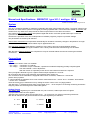
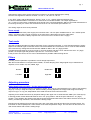
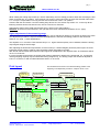
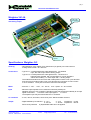
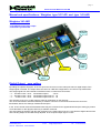
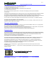
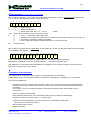
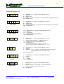
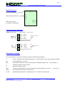
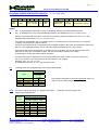
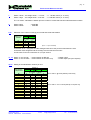
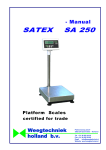
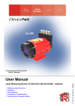
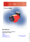
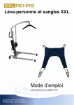
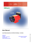
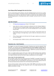
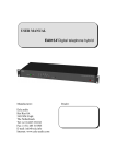
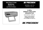
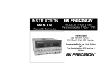
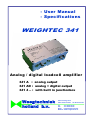
- User Manual
- Specifications
WEIGHTEC 341
Analog / digital loadcell amplifier
341 A : analog output
341 AD : analog + digital output
341 4 .. : with built in junctionbox
Weegtechniek
holland b.v.
Patroonsweg 23-27
3892 DA Zeewolde the Netherlands
Tel.
Fax.
Email
Website
+31 36 522 20 30
+31 36 522 20 60
[email protected]
www.weegtechniek.nl
pag.1
Manual and Specifications: WEIGHTEC type 341-1 and type 341-4
PCG/C 341 manual + specs eng.27-01-09
System
The 341 is a loadcell amplifier for maximum 8 loadcells with strain gauge measuring system. The power supply for the
loadcells, the sense return system en the signal processing operates with a 184 Hz sine wave based AC current, that
results into a very stable zero and prevents for thermocouple effects in the cable connections.
The system is fully hardware based and operates digital with 92 Hz conversion speed based upon continuous
synchronous detection.
Therefore the operation of the 341 is independent of software programs, jumpers or potmeter settings.
The parameters are all set by Dil-switches.
Sense return measurement compensates automatically for deviations caused by changes in temperature on longer
cable connections. So: long loadcell cables may be applied with a 341.
The wide input sensitivity range allows to install up to more than 7 times the required loadcell capacity,
with still the full analog output signal available. Thus a sturdy scale with wide overload range can be made.
With the built in loadcell simulator the complete 341 may be checked without the need of removing the loadcell
connections.
Connections
Inputs
There are two version of the 341 available:
- 341- 1A(D)
- 341- 4A(D)
- connection of 1 loadcell
- connection of up to 4 loadcells, 4 potmeters included for adjusting possibly unequal signals
from the loadcells: “corner adjustment”.
With this version no separate junction box for the loadcell connections is required.
The input signal is allowed to go 4% negative. Minimal input impedance is 43,75 Ω.
All connections are short circuit protected, signal against power supply too.
The connections of the loadcells are equipped with Phoenix connectors, suitable for 4- and 6-wire
(sense return) systems.
If 4-wire loadcells are applied a short circuit must be made between the “+ sense” and “+ excitation” and between
“- sense” and “- excitation”.
These shortcuts may be switched on too by setting the switch: SENSE in the “on”(high) position.
Just above the 1st loadcellconnector there are test pads TP13 . . 19 for the pins of a checking measuring instrument.
Outgoing cables are led through PG7 metal cable glands.
Analog Output
The analog output signal may be connected with a 3 pole connector, cable output via a PG7 gland.
A (foil)shielded cable has to be applied.
Just above this connector there are test pads TP13 . . 19 for the pins of a checking measuring instrument.
With the Dil-switches on the print board the kind of output signal may be selected:
0 – 10 V
0 – 20 mA
2 – 10 V
4 – 20 mA
WEEGTECHNIEK HOLLAND B.V.
Patroonsweg 23-27
3892 DA ZEEWOLDE The Netherlands
Website www.weegtechniek.nl
Email
info@ weegtechniek.nl
Tel
Fax
+31 36 522 20 30
+31 36 522 20 60
pag. 2
MANUAL WEIGHTEC 341
Changing the setting of the analog output has no effect on an already adjusted span setting.
Not even if changed from offset to no-offset: f.e. from 4 – 20 mA to 0 – 20 mA.
In the TEST mode, with the Dil-switches: SENSE / TEST in “on” position (both the switches high),
the built in loadcellsimulator is switched on in stead of the connected loadcells. The output signal will be
10.1 V resp 20.2 mA precise, independent of the signal of the connected loadcells. Without connected loadcells this is
functioning correctly too. All the zero switches are to be set “off” and all the span switches “on”.
The analog output is short circuit protected.
Power supply
The 341 needs a 230 VAC power supply and consumes max. 2 W. As option available with 19 - 36 V AC/DC power
supply. Connection with a 3 pole connector on the print board, cable output via a PG7 cable gland.
A clean earth connection is always required. Do not connect a 24 V version to 230 V supply !
Test mode
The built in loadcell simulator provides a test facility for the complete instrument , in case of doubts about the output
signal or the loadcell signal. It switches off the connected loadcells and connects the 341 to a built in stable loadcell.
This is achieved by setting both the Dil-switches: SENSE en TEST in the “on” (high) position.
Provided all the Dil-switches for ZERO are set in “off” (low) position and all the SPAN switches are set in “on” (high)
position, the output signal will generate a precise 10.1 V or 20.2 mA value.
If this proves to be correct, the 341 can be eliminated as a possible malfunctioning device.
Filters
Internally a fixed 2 pole filter is provided to cut off all high frequencies.
With the two Dil-switches on the print board: FILTER , an extra damping of the weigh signal may be switched on if
required, in four modes: out, low, middle, high:
No filter
Middle filter
Low filter
High filter
Adjusting procedure
Digital dead load correction, for the analog output only
The dead load of a weighing machine (its platform, hopper, etc.) may be compensated for up to 100% of the weighing
range (2.4 mV/V) in steps of 0.038 µV/V. With this setting correctly adjusted, the empty scale will give an analog
output of 0 (2) V or 0 (4) mA, independent of the dead load of the scale’s structure itself.
Adjusting for the dead load is done by empirical setting of the upper row of 16 Dil-switches: ZERO (see: Print layout).
In starting position all the dead load switches are in “off” (low) position and all the span switches in “on” (high)
position. In this situation the analog output signal represents the dead load value of the scale’s structure and may be
read by a measuring instrument, connected to the analog output.
Following the Dil-switches from the left to the right, each next switch has half the value of its preceding switch. The
first switch on the left (MSS) has a value of 50% of the total compensation range. The next one has 25% and so on
until the last switch with 0.0015% setting range.
WEEGTECHNIEK HOLLAND B.V.
Patroonsweg 23-27
3892 DA ZEEWOLDE The Netherlands
Website www.weegtechniek.nl
Email
info@ weegtechniek.nl
Tel
Fax
+31 36 522 20 30
+31 36 522 20 60
pag. 3
MANUAL WEIGHTEC 341
While reading the analog output value (f.e. with a multimeter), the zero setting procedure starts with switching the first
switch to the left into “on” position. If the read out now shows a value below zero (or below the selected offset value:
2 V / 4 mA) the compensation is too big and the switch should set back in “off” position.
Continue with the next switch. If now the reading stays above zero, the switch may remain “on”. In this way all the
following switches should checked and set, until an exact zero is achieved.
Changing the setting of the dead load switches has no effect on the span settings !
Attention: at least one of the switches in the right side zero block of 8 switches should be set “on” (high).
Digital adjustment of the measuring range
Using the lower row of 16 Dil-switches: SPAN , the span may be adjusted in relation to the actual net load on the scale.
The adjustment procedure is equal to the dead load adjustment. However the starting position is with all the Dilswitches “on” (high, = 100% amplification).
The amplifier is 7 x over rated. That means that up to 7 x higher loadcell capacity can be installed, whilst the analog
output signal still gives its full range.
After adjusting the dead load compensation, a known mass (f.e. certified weights) should be placed upon the scale.
Preferably the full weighing capacity. Now the analog output signal will be too high.
With the Dil-switches (start at the left) the output signal can be adjusted to the required value. At full load this will be
10.00 V or 20.00 mA.
If not the full load can be placed, the output signal must be adjusted in relation to the actual load. F.e. a scale with
1000 kg weighing capacity may be loaded with 500 kg weights only. The analog output now should be adjusted at
5.00 V or 10.00 mA, or with an offset selected at 6.00 V or 12.00 mA.
Print layout
The Dil-switches are shown in the advised starting position at the
beginning of an adjustment procedure. Output is set as 0-10V.
4 potmeters
“corners” 341-4
3 x extra loadcell
connections 341-4
at least one switch of this
8-block should be set high
WEIGHTEC 341
\
\
1
2
3
4
5
6
7
1
2
3
sense return
short cut
15
14
13
18
19
6
7
ON
OFF
ON
OFF
ZERO
MSB
\
2
3
4
5
6
trafo
7
digital
output
loadcell connection 341-1
analog
output
selection
filter
setting
SIDE A
C 2453
WEEGTECHNIEK HOLLAND B.V.
Patroonsweg 23-27
3892 DA ZEEWOLDE The Netherlands
FILTER
C 2453
Website www.weegtechniek.nl
Email
info@ weegtechniek.nl
not applied in
24 V version
24 V AC/DC
excitation
(option)
analog
output
~
TP22
1
TP20
7
TP21
6
-SENSE
5
- EXCITATION
4
+SENSE
+SIGNAL
3
+EXCITATION
SHIELD
2
-SIGNAL
1
230VAC
+ - GND
ANAL.OUT
Tel
Fax
~
L1 N E
\
sub-print digital
output (option)
ON
OFF
SPAN
TEST
16
5
loadcell
simulator
SENSE
17
4
not in 24V
version
+31 36 522 20 30
+31 36 522 20 60
pag. 4
SPECIFICATIONS WEIGHTEC 341
Weightec 341 4A
IP 65 / 68
alu housing
with built in junction box
and analog output
230 VAC or
24 V AC/DC
excitation
analog
output
1 or 4 loadcell
inputs
Specifications Weightec 341
Housing
: Cast aluminum, grey coated, IP 65, dimensions (ex glands) 120 x 220 x 82 mm
4 fixing holes 6,5 mm : 82 x 204 mm
Connections
: Type 341-1 : 3 nickel plated brass cable glands PG7: one loadcell
input, the mains input and the analog output.
Type 341-4 : 6 nickel plated brass cable glands PG7, 4 of these for 4
loadcell inputs (parallel, with compensation for corner deviations
without shunt effect), 1 x mains input and 1 x analog output
The loadcell terminals and connectors with nickle plated contacts. One 3 pins terminal
and connector for analog output. One 3 pins terminal and connector for 230 V mains
or 24 V excitation. The 3 pins connectors cannot be interchanged.
Mains
: 230 VAC -/- 15%. . .+10%, 48. . .62 Hz, 2 VA. Option: 19 - 36 V AC/DC
Input
: Minimum input impedance 43 Ω. Maximum sensitivity 0.068 µV/V
Negative input up to 4% accepted. Full analog output may be achieved already at an input
signal of minimal 0 . . . 0.28 mV/V. Max input signal 0 . . . 2.4 mV/V.
The amplifier input may be shorted with the LC excitation.
LC excitation
: 3 VAC, 184 Hz, sine wave, short circuit proof. Max 8 loadcells of 350 Ω.
Output
: Digital settable by Dil switches : 0 - 10 V
2 - 10 V
Impedance > 10 kΩ
0 - 20 mA
4 - 20 mA Impedance < 500 Ω
Short circuit protected. A (foil)shielded cable has to be applied.
WEEGTECHNIEK HOLLAND B.V.
Patroonsweg 23-27
3892 DA ZEEWOLDE The Netherlands
Website www.weegtechniek.nl
Email
info@ weegtechniek.nl
Tel
Fax
+31 36 522 20 30
+31 36 522 20 60
pag. 5
SPECIFICATIONS WEIGHTEC 341
Measuring
system
: 92 Hz AC system, partial digital, based on continuous synchronous detection of the
LC's sine wave excitation. Hardware design, not software or programming dependent.
Connectors :
loadcell
1
2
3
4
5
6
7
shield
- signal
+ signal
+ excitation
+ sense
- sense
- excitation
analog
output
230 VAC
+
GND shield
E
N
L1
24V AC/DC
(option)
~
~
earth
neutral
line
(DC polarity
not relevant)
Sense return
: Automatic compensation for alterations in LC excitation by temperature effects on
longer cables, directly on the signal input amplifier via synchronous detection principle.
There is no cable length limitation because of the sense return and the sine wave
excitation of the loadcells.
The sense return has to be switched off if loadcells with 4-wire system are applied:
switch: SENSE to be set “on”(high).
Corners
: Each of the 4 LC inputs (type 341-4) is equipped with a 20-turn potmeter of 3.3 Ω
(impedance at 4 loadcells), to compensate for deviations in the loadcell outputs.
Changing the setting of one potmeter does not effect the output of the other 3 loadcells.
This makes corner calibration very simple.
Dead load
adjustment
: Digital settable 100% dead load compensation (16 bit = 1 : 65,500) by Dil switches in
steps of 0.037 µV/V. Settability is 0.019 µV/V + or - the required zero value.
Changing the dead load setting has no effect on the span adjustment.
Span
adjustment
: Digital settable amplifier (16 bits = 65,500 counts) by Dil switches, resolution per count
dependent on the maximal signal input value.
F.e.: LC signal Max = 2.4 mV/V Æ 1 count = 0.325 µV/V (1 : 7,400)
LC signal Max = 0.5 mV/V Æ 1 count = 0.068 µV/V (1 : 35,500)
The span setting will automatically adapt itself to the calibrated output value if the
analog output setting is switched from: 0-10V / 0-20mA to: 2-10V / 4-20 mA.
Changing the span setting too has no effect on the dead load adjustment.
Filters
: - Internal analog 2 pole 2.8 Hz.
- Digital filter, settable by Dil switches in 4 stages, 2 pole, for the analog output only.
Loadcell
simulator
: Test switch connects a built in loadcell simulator to the amplifier input in stead of the
present loadcells. The loadcells may stay connected. Analog output at full span and no
dead load setting will be 10.1 V or 20.2 mA precise. Functions too without connected
loadcells.
Accuracy
: Over all
not linearity + hysterese + not reproducibility
temperature
on zero
per 10° C
on span
per 10° C
WEEGTECHNIEK HOLLAND B.V.
Patroonsweg 23-27
3892 DA ZEEWOLDE The Netherlands
≤ 0,03 %
≤ 0,01 %
≤ 5 ppm
≤ 0,01 %
Website www.weegtechniek.nl
Email
info@ weegtechniek.nl
Tel
Fax
+31 36 522 20 30
+31 36 522 20 60
pag. 6
SPECIFICATIONS WEIGHTEC 341 AD
Manual and specifications: Weightec type 341 1AD and type 341 4AD
Weightec 341 4AD
- with DIGITAL and analog output
- with built in junction box
IP 65 / 68
enclosure
230 VAC or
24 V AC/DC
excitation
analog
+ digital
output
A/D converter
“Digi print”
1 or 4 loadcell
inputs
Digital Output, zero setting
By adding the optional “digi-print” to the 341 upon the connectors on the main print board, a digital output of the
weight signal is created. The output offers the choice of a RS 232 configuration or a Current Loop transmission.
The weight signal from the loadcells is transformed into a number that counts from:
- 0 … 400.000 counts : 19 bit
- 0 … 200.000 counts : 18 bit
- 0 … 20.000 counts : 15 bit
transmission speed
3,8 Hz
transmission speed max. 31 Hz
transmission speed max. 31 Hz
The selection of the 18 or 15 bits output is made by a Dil switch on the digi print.
The 19 bit transmission should be started by a software command. In this mode the direct A/D counts are
transmitted, without the settings of dead load and span.
In the 18 and 15 bits mode the transmitted value may be corrected for the applied dead load (zero setting) by means
of one Dil switch on the digi print and/or by a software command.
The span setting is still done with the span switches on the main board of the 341. Here both the digital value as well
as the analog output are simultaneously adjusted to the required output signal / counts.
WEEGTECHNIEK HOLLAND B.V.
Patroonsweg 23-27
3892 DA ZEEWOLDE The Netherlands
Website www.weegtechniek.nl
Email
info@ weegtechniek.nl
Tel
Fax
+31 36 522 20 30
+31 36 522 20 60
pag. 7
SPECIFICATIONS WEIGHTEC 341 AD
In the datastring not only the weight value is transmitted, but also :
- the sign of the weight value (+ or - ) or exact zero ( blank: )
- the (automatic) zero setting is active (Z)
- the weight value is in motion (M) or there is a standstill (S) of the weight value
- the weigh speed may be sent (V)
With a special command the speed of the in- or decrease of the weight (V) value may be transmitted in
counts/second.
Transmission may be selected as for the continuous mode or one (or more) transmissions after a software command.
The setting for continuous transmission is automatically selected by the setting of the call number of the 341.
At nr. @ only continuous transmission is default selected, the rate of transmission may be selected by Dil switches on
the digi print. By a software command the continuous transmission always may be switched on and off
The 341 allows to be combined with Weightec 348 weight processors in one bus with 2 x 15 amplifiers maximum.
The analog output stays available if a digi-print is applied.
The digi-print may be added later on too, no reprogramming of the 341 is necessary. At older versions of the 341 a
change in the power supply may be required.
Test mode: loadcell simulator
The internal loadcell simulator is activated by setting both the Dil-switches: SENSE en TEST in the “on” (high) position.
The connection with the actual loadcells may be continued.
Provided any zero setting has been deleted and all the SPAN switches are set in “on” (high) position, the output value
will be 2,000 or 20,000 counts, depending on the chosen resolution with switch 7.
If this proves to be correct, the 341 can be eliminated as a possible malfunctioning device.
Communication
The method of connection of the digital output connector determines whether the 341will used with a RS 232 serial
output or with its Current Loop output. Applying longer communication cables and in any circumstance with the risk of
pulses and radio interferences, the CL method is strongly advised, since a current based transmission is less
sensitive for this kind of disturbances of the transmissions.
The in/outputs in CL mode are galvanic separated from the 341 by opto couplers.
The communication protocol is compatible with the Weightec 348 en 348-2. Both the models 341 and 348 may be
connected in a bus system with the Weightec interface 848 up to a maximum of 2 x 15 weighing machines.
The identification (call)numbers of 341’s is always an undercast letter (f.e.: a ). Sending a command with the
identification (call)number as a capital (f.e.: A ) will create a string protocol identical to the Weightec 348 protocol.
Any answer from a 341 however always starts with its call number as an undercast letter.
In continuous sending mode this option is not available.
A Weightec 341 set on identification nr. (@) will (default) send continuously with the speed rate as chosen
by switch 9 en 10 .
If set on identifications numbers a . . o one (or more or continuous) transmission only will be sent after a received
software command.
Character frame
Start bit
Data bit
1
7
ASCII
Parity
1
even
Stop bit
2
1
2
start lsb
WEEGTECHNIEK HOLLAND B.V.
Patroonsweg 23-27
3892 DA ZEEWOLDE The Netherlands
3
4
5
6
7
8
9
10
11
parity
even
stop
stop
Website www.weegtechniek.nl
Email
info@ weegtechniek.nl
Tel
Fax
+31 36 522 20 30
+31 36 522 20 60
pag. 8
SPECIFICATIONS WEIGHTEC 341 AD
String assembly : protocol 341 / protocol 348
After receipt of a question ( ? as 2e byte, see: “Commands and questions”) with an undercast letter as call number,
( f.e.: a) the 341 will respond by sending its standard string :
1
2
3
4
5
6
7
8
9
10
a
+
W
W
W
W
W
W
M
CR
1
: call nr. = @ and a t/m o
2
: + of = polarity weight value
= weight value exact zero, + or - ½ count
= blank
3 ..8 : weight value, preceding zero’s are shown as blanks
9
:M
S
Z
V
=
=
=
=
motion, no standstill of the weight value
standstill of the weight value (according to conditions from the table for switch 4,5,6 on pag. 10)
zero setting in operation, waiting for standstill
shown value is the speed of weight in/decrease, in counts per second
10
: Carriage Return
After receipt of a question with an capital letter as call number (f.e. A), the 341 will respond with a string according
to the Weightec 348 protocol :
1
2
3
4
5
6
7
8
9
10
11
12
13
14
15
16
a
#
G
+
W
W
W
W
W
W
M
CR
In the 3e character a “G” means: this is a weight value, a “V” indicates a weight speed value.
Data that are not available in the 341 are sent as blanks: . See manual Weightec 348-2.
This difference in call numbers makes it possible to use Weightec 341’s en 348’s at random in one bus system,
both using the same format of the strings.
Commands and questions:
The communication is full duplex, ASCII coded, no handshake protocols are needed.
A string always has to start with the identification (call)number, followed by a ? (question) or a ! (command)
The functions available are:
- Request to send string, with the choice whether 1 string only or more (up to 9 strings) will be transmitted.
Sending more strings is meant to be used to check the correct receipt of a string, they all contain identical
information.
In the mode: “1 x per 4 seconds transmission” however the measured value will be refreshed every
transmission.
- Switch to continuous transmission.
- Stop continuous transmission, even if Dil-switch setting is set on continuous transmission.
- Request to send A/D conversion value: 1 : 400.000 count
- Request to send weight speed in counts per second (in- or decreasing weight value)
(very useful for constant flow control !)
- Set zero (with motion control)
- Delete zero setting
WEEGTECHNIEK HOLLAND B.V.
Patroonsweg 23-27
3892 DA ZEEWOLDE The Netherlands
Website www.weegtechniek.nl
Email
info@ weegtechniek.nl
Tel
Fax
+31 36 522 20 30
+31 36 522 20 60
pag. 9
SPECIFICATIONS WEIGHTEC 341 AD
Commands available are:
a
?
W
1
CR
1 x transmission
a
?
W
C
CR
start continuous
transmission
@
?
W
0
CR
Stop sending
a
?
A
..
CR
Send A/D value
a = identification nr. (may be number @ and a until o)
? = what is . . .
W = weight value
1 = send 1 x (0 until 9 possible, an equal number of strings will follow)
CR = carriage return
a = identification nr. (may be number @ and a until o)
? = what is . . .
W = weight value
C = send continuously (stop it with this command and a 0 in this byte)
CR = carriage return
@ = identification nr. (may be number @ and a until o)
? = what is . . .
W = weight value
0 = stop continuous transmission
CR = carriage return
a = identification nr. (may be number @ and a until o)
? = what is . . .
A = A/D conversion value: 1 : 400.000 counts *)
.. = 0 until 8 or C (see commands above)
CR = carriage return
*) the zero and span settings are neglected in this value,
the transmission speed of this averaged value is max. 3,8 Hz.
a
!
Z
a = identification nr. (may be number @ and a until o)
! = execute . . .
Z = set zero (+ or - ½ count, or the average out of the remaining
weight variations over max. 6 seconds)
CR = carriage return
CR
Set zero
a
!
Z
C
R
X
Delete zero
setting
a
?
V
..
CR
Weigh speed
WEEGTECHNIEK HOLLAND B.V.
Patroonsweg 23-27
3892 DA ZEEWOLDE The Netherlands
a = identification nr. (may be number @ and a until o)
! = execute . . .
Z = zero . .
X = . . delete
CR = carriage return
a =
? =
V =
.. =
CR =
identification nr. (may be number @ and a until o)
what is . . .
speed of weight in- or decrease in counts per second
0 until 8 or C (see commands above)
carriage return
Website www.weegtechniek.nl
Email
info@ weegtechniek.nl
Tel
Fax
+31 36 522 20 30
+31 36 522 20 60
pag. 10
SPECIFICATIONS WEIGHTEC 341 AD
Digi Print lay out
1
8
9
16
Dil-switches settings
1
2
3
4
5
Communication connector
µP
See layout on pag. 3
for position of the digi print
C2354
Communication connector
Cable type 22 TPST
RXD = passive
1
RS 232
mode
RXD
TXD = active
(black)
2
Short cut with pin 1
3
TXD
switch 11 and 12
4
Short cut with pin 3
5
Common (orange + brown)
(red)
high
Connect shield on one side only
+ RXD
(black)
2
- RXD
(brown)
switch 11 and 12
3
+ TXD
(red)
down
4
- TXD
(orange)
5
Connect shield on one side only
1
CL
mode
Parameter settings
The 16 Dil-switches on the Digi Print allow the setting of the following parameters:
1
- set zero, automatic zero setting at switching on, or restore previous zero value, delete zero setting
2,3
- 4 filter settings (5,6 - 0,12 Hz)
4-6
- the number of variation in counts that conclude to standstill (8 steps of 0,5 … 100 counts/sec.)
7
- resolution 200.000 or 20.000 counts
8
- Baud rate 19.200 or 9.600
9,10
- number of transmissions per second at continuous sending mode (31 x per sec. … 1 x per 4 sec.)
11,12
- communication as RS 232 or Current Loop
13 - 16
- identification (call)number, and (default) yes or no continuous sending mode
WEEGTECHNIEK HOLLAND B.V.
Patroonsweg 23-27
3892 DA ZEEWOLDE The Netherlands
Website www.weegtechniek.nl
Email
info@ weegtechniek.nl
Tel
Fax
+31 36 522 20 30
+31 36 522 20 60
pag. 11
SPECIFICATIONS WEIGHTEC 341 AD
Functions settable with the DIL-switches
1
2
(auto)
zero
3
4
5
6
no motion sign
over .. counts
filter
7
8
x
10
Baud
rate
(0 = off = switch down)
9
10
transmission
frequency
11
12
CL /
RS 232
13
14
15
16
Identification number
Switch:
1
Off = no zero setting at switching on the 341, an already existing zero setting will be restored
On = at switching on the 341 it will automatically set zero after standstill (max 6 sec. calculated average)
With the 341 in switched-on position, a set zero is executed by setting the switch from “off” to ”on”, after
standstill of the weight value (max 6 sec. calculated average)
If the switch is maintained in the “on” position, the 341 will set a new zero each time the 341 is switched
on again. The previous zero will be deleted.
If there is any risk that the 341 is switched on with a loaded (weight on the) scale, this load will be set to zero,
which is not a preferable situation. It such cases the switch should be set in the “off” position.
If the switch, after a zero set operation, is set back to the “off” position, the 341 will store the zero value.
Each time now the 341 is switched on again, this zero value will be used for zero setting.
At switching on no new zero setting will be executed.
The zero value may be deleted from its memory by setting the switch, within 2 seconds, 2 times from
“off” to “on” position. If necessary first set back the switch to “off” position.
Example: “(off) - on - off - on - off”.
The software command ” A ! Z X ” has the same result.
2, 3
4 filtering modes for the digital weight value output are available:
Switch nr.
2
3
Filter
off
low
middle
high
4,5,6
Setting
(0 = down
1 = high)
5,60 Hz
1,25 Hz
0,40 Hz
0,12 Hz
0
0
1
1
The setting of the filters on the main print board of the 341
effects only the analog output signal.
0
1
0
1
“No motion” sign in the string: “S” appears if less than . . counts per second change of the
weight value is determined:
Change in
counts
4
0,5
1
2
5
10
20
50
100
0
0
0
0
1
1
1
1
Switch nr.
5
6
Setting (0 = down, 1 = high)
0
0
1
1
0
0
1
1
WEEGTECHNIEK HOLLAND B.V.
Patroonsweg 23-27
3892 DA ZEEWOLDE The Netherlands
0
1
0
1
0
1
0
1
Website www.weegtechniek.nl
Email
info@ weegtechniek.nl
Tel
Fax
+31 36 522 20 30
+31 36 522 20 60
pag. 12
SPECIFICATIES WEIGHTEC 341 AD
7
Switch 7 down : the weight value x 1 is sent
Switch 7 high : the weight value x 10 is sent
: 0 - 20.000 counts ( 0 - 2 mV/V)
: 0 - 200.000 counts ( 0 - 2 mV/V)
The “no motion” calculation is based upon the number of counts that has been selected with this switch.
8
Switch 8 high
Switch 8 down
9,10
Selection of the number of strings per second that will be transmitted:
Strings per
second
31
8
1
0,25
: 19.200 Bd
: 9.600 Bd
9
Switch nr.
10
Setting
(0 = down, 1 = high)
0
0
1
1
0
1
0
1
(0,25 = 1 x per 4 seconds)
At selection 8 en 1 strings/second the averaged value since the previous transmission is sent.
At selection 0,25 strings/second the average over the last second is sent.
An A/D value is sent at a maximum of 3,8 x per second.
11, 12 Switch 11 and 12 high : communication as RS 232
Switch 11 and 12 down : communication as Current Loop
13-16
: voltage output
: current output (via opto couplers)
Setting of the identification number per 341:
Identification
(call) number
13
@
a
b
c
d
e
f
g
h
i
j
k
l
m
n
o
0
0
0
0
0
0
0
0
1
1
1
1
1
1
1
1
Switch nr.
14
15
Setting
(0 = down, 1 = high)
0
0
0
0
0
1
0
1
1
0
1
0
1
1
1
1
0
0
0
0
0
1
0
1
1
0
1
0
1
1
1
1
WEEGTECHNIEK HOLLAND B.V.
Patroonsweg 23-27
3892 DA ZEEWOLDE The Netherlands
16
0
1
0
1
0
1
0
1
0
1
0
1
0
1
0
1
A 341 with nr. @ sends (default) continuously
A 341 with nr. a t/m o sends (default) on request only
Website www.weegtechniek.nl
Email
info@ weegtechniek.nl
Tel
Fax
+31 36 522 20 30
+31 36 522 20 60