1
User's Manual for
SafeRoof® Version 2.1:
A Program for the Analysis
of
Storage Tanks
with
Frangible Roof Joints
Manual Release 2.1
February, 2005
Version 2.0 by
Thunderhead Engineering Consultants, Inc.
1006 Poyntz Ave.
Manhattan, KS 66502-5459
Version 1.0 by
Zhi Lu
Mechanical Engineering Department
Kansas State University
Manhattan, KS 66506
Table of Contents
TABLE OF CONTENTS
INTRODUCTION .................................................................................. 1
INSTALLING SAFEROOF ..................................................................... 3
USING SAFEROOF ............................................................................. 4
FILE MENU.................................................................................... 4
New ........................................................................................ 4
Open....................................................................................... 4
Save ....................................................................................... 4
Save as .................................................................................. 4
Print ........................................................................................ 5
Exit ......................................................................................... 5
DESIGN MENU............................................................................... 5
Auto Design ............................................................................ 5
Appendix A Design ................................................................. 7
User Design............................................................................ 7
Foundation.............................................................................. 8
Dead Weight on Shell............................................................. 9
Anchors .................................................................................. 9
ANALYSIS MENU ............................................................................ 9
Solution Controls .................................................................... 9
Liquid Level .......................................................................... 11
Combustion Parameters....................................................... 11
Begin Calculation.................................................................. 12
API 650 Calculation .............................................................. 13
Overturning Stability ............................................................. 13
POSTPROCESS MENU .................................................................. 14
Access Data ......................................................................... 14
Plot ....................................................................................... 14
Zoom In ................................................................................ 16
Zoom Reset .......................................................................... 16
Reverse Contour .................................................................. 16
Displace Scale...................................................................... 16
List........................................................................................ 16
List Font................................................................................ 16
HELP MENU ................................................................................ 16
Index..................................................................................... 16
Using Help ............................................................................ 17
About .................................................................................... 18
EXAMPLE PROBLEM ........................................................................ 19
STEPS ........................................................................................ 19
THEORY AND IMPLEMENTATION: STATIC ANALYSIS ............................ 22
Table of Contents
AUTOMATIC DESIGN .................................................................... 22
STRUCTURE ANALYSIS ................................................................. 22
Shell Elements...................................................................... 22
Foundation Elements............................................................ 27
Finite Element Mesh Generation .......................................... 29
Nonlinear Solution Procedure............................................... 33
COMBUSTION ANALYSIS ............................................................... 34
Solution Procedure ............................................................... 34
Combustion Wave Geometry................................................ 36
Burning Velocity.................................................................... 40
Venting ................................................................................. 41
FRANGIBLE JOINT FAILURE ........................................................... 42
THEORY AND IMPLEMENTATION FMA-3D ANALYSIS........................... 45
VERIFICATION PROBLEM .................................................................. 48
REFERENCES .................................................................................. 54
ACKNOWLEDGMENTS ....................................................................... 55
AUTHOR’S COMMENTS ON PROGRAM STATUS AND FUTURE
DEVELOPMENT .................................. ERROR! BOOKMARK NOT DEFINED.
BLANK PAGES FOR USER NOTES ....... ERROR! BOOKMARK NOT DEFINED.
INDEX ............................................................................................. 56
Introduction
Page 1
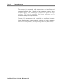
INTRODUCTION
This manual describes the use of SafeRoof® , version 2.0, a
program that has been developed to design and analyze storage
tanks with frangible roof joints. The program is the result of a
research program into frangible joint design, sponsored by the
American Petroleum Institute and the Pressure Vessel Research
Council.
API 650 (API, 1993) gives design rules for tanks used to store
flammable liquids which could be subjected to sudden overpressurization.
Over-pressurization can occur due to the
ignition of flammable vapors and can lead to the catastrophic
loss of tank integrity. Undesirable modes of failure include loss
of the shell-to-bottom joint or failure of the tank shell, either of
which could result in loss of containment and spillage of the
contents. To reduce this hazard, the frangible roof-to-shell joint
is designed to fail first, providing a large venting capability to
relieve the pressure. Research was initiated to address concerns
about the general applicability of the present frangible joint
design rules.
As part of this research, scale model tanks were dynamically
tested by igniting an air/methane mixture in the tanks.
Experimental observations showed that failure initiated when
yielding was reached at the roof-to-shell joint. This was followed
by buckling at the joint, tearing of the weld, and failure
propagation in the weld and joint. Detachment of the roof
relieved pressure in the tank. Because pressure relief does not
occur instantaneously, the peak pressure in the tank can be
larger than the failure initiation pressure. Further details of
the model and testing are documented in the final research
report, Swenson, et al., (1994).
SafeRoof incorporates the results of this research. It includes
design, analysis, and post-processing modules. In the design
module, the user can input tank parameters and SafeRoof will
develop a design following API 650 guidelines. This design can
either be accepted or modified. The user can then analyze the
stresses and displacements in the tank at pressures
corresponding to selected tank failure modes. The analysis can
be coupled to a combustion/joint failure analysis. The pressures
at each failure mode can be used to help evaluate safety of the
tank due to overload pressures.
SafeRoof User's Guide, Release 2.0
Page 2
Introduction
This manual is arranged with instructions on installing and
running SafeRoof first. Details of the automatic design, finite
element theory, and combustion analysis are given in later
sections. The user is reminded that many questions can be
answered using the help functions.
Version 2.0 incorporates the capability to perform dynamic,
large displacement, elastic-plastic analyses of tank response.
This was accomplished by incorporating FMA-3D (FMA, 2004)
SafeRoof User's Guide, Release 2.0
Installing SafeRoof
Page 3
INSTALLING SAFEROOF
SafeRoof runs in Microsoft 9x, NT, 2000, and XP. Using the CD,
installation is run automatically. If installation does not start,
select Run C:\setup, where C is the name of the drive of the
installation disc. The user can now run SafeRoof.
SafeRoof User's Guide, Release 2.0
Page 4
Using SafeRoof
USING SAFEROOF
SafeRoof runs in Microsoft Windows, so a basic knowledge of
Windows usage is assumed. The menus are designed so that the
user works from left to right to define, perform, and post-process
results.
This section provides a description of the menus and dialog
boxes in SafeRoof. Example problems are given in the following
section.
SafeRoof is started by either selecting the executable file in the
file directory or by creating a program group with SafeRoof as a
program item. When SafeRoof is defined as a program item, an
icon will be displayed.
FILE MENU
When SafeRoof is started, the user is shown a blank window
with menu selections. It is necessary to select the FILE MENU
before an analysis can be performed or previous results
accessed. After selecting FILE MENU, the following choices are
available.
New
New is used to define the file name of a new analysis. The user
can select the directory and file name.
Open
Open can be used to open a previous analysis. When this is
done, the user can immediately proceed to the POSTPROCESS
MENU to examine previously calculated results. Alternately, the
user can modify the portions of the design or analysis options
and perform new calculations.
Save
Save is used to save a design or results. Only active if a design
or analysis has been performed.
Save as
This allows the user to save the current design under a new
name. However, this does not make copies of the results files.
Only active if a design has been performed.
SafeRoof User's Guide, Release 2.0
Using SafeRoof
Page 5
Print
Print sends the current window display to the default printer.
When printing a plot of the design or results, using the
landscape mode of the printer will likely result in the best fit of
the graphic image on the page. Portrait mode is best for
listings.
Exit
Exits the program.
DESIGN MENU
The DESIGN MENU is used to define the tank for which a design
is requested. The user supplies sufficient data for SafeRoof to
design a tank following API 650 rules. After a design is
proposed the user can override the suggestion and define a tank
using a different design.
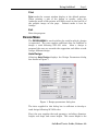
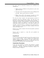
Auto Design
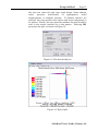
Selecting Auto Design displays the Design Parameters dialog
box shown in Figure 1.
Figure 1: Design parameters dialog box
The data supplied in this dialog box is sufficient to develop a
tank design following API 650 rules.
First, the user supplies the tank geometry, including: diameter,
height, roof slope, and course height. The course height is the
SafeRoof User's Guide, Release 2.0
Page 6
Using SafeRoof
height of the sheet steel used to form the tank sides.
addition, the user defines the direction of the top angle.
In
The corrosion allowances, maximum design height of the liquid,
and specific gravity of the liquid to be stored are also defined.
Note that the liquid height defined in this dialog box is used for
design. The user can specify a different height for use in the
stress analyses.
The material to be used in the design is selected. The allowable
stress values for each material are those defined in API 650. If
desired, the user can scroll to the bottom of the list and add a
user-defined material. If this is done, the user will be prompted
for the allowable stresses for the user-defined material.
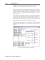
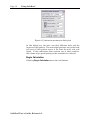
After the tank and parameters are defined, the user selects OK.
SafeRoof will then design a tank according to API 650 rules,
Figure 2.
Figure 2: Window showing tank design
SafeRoof User's Guide, Release 2.0
Using SafeRoof
Page 7
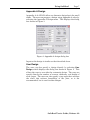
Appendix A Design
Appendix A of API 650 offers an alternate design basis for small
tanks. The user can prepare a design using Appendix A rules by
selecting the Appendix A Design menu. This displays the dialog
box shown in Figure 3.
Figure 3: Appendix A design dialog box
Input to this design is similar as that described above.
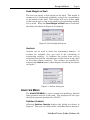
User Design
The user can also specify a design directly by selecting User
Design, which displays the dialog box shown in Figure 4. This
allows the user to over-ride the automatic design. The user can
specify directly the number of courses, thickness, and height of
each course. The user can also specify a top angle that overlaps
the shell; this reduces frangibility of the joint, so is not
recommended, but is used in some designs.
SafeRoof User's Guide, Release 2.0
Page 8
Using SafeRoof
Figure 4: User defined menu
Foundation
As described in the Theory Section, the model assumes that the
tank rests on an elastic foundation. Two stiffnesses and a
radius are used to describe the foundation. These can be used to
model a tank resting on a sand foundation, with concrete
supports under the shell. Inside the specified radius, the first
stiffness is used and outside the radius, the second stiffness is
used. Selecting Foundation displays the foundation dialog box
shown in Figure 5.
Figure 5: Foundation stiffness dialog box
SafeRoof User's Guide, Release 2.0
Using SafeRoof
Page 9
Dead Weight on Shell
The user can specify a dead weight on the shell. This weight is
assumed to be distributed uniformly around the circumference
at the bottom of the shell. This weight will act to reduce uplift
of the bottom and is used in the analysis of overturning stability
due to wind. When the Dead Weight on Shell menu is selected,
the dialog box shown in Figure 6 is displayed.
Figure 6: Dead weight dialog box
Anchors
Anchors can be used to resist the overturning moment. If
anchors are included, they are used in the calculation of
overturning stability. In addition, the anchor force will be
distributed around the circumference of the bottom of the shell
in the finite element analysis. The anchors are specified by
selecting the Anchor menu, which displays the dialog box shown
in Figure 7.
Figure 7: Anchor dialog box
ANALYSIS MENU
The ANALYSIS MENU is used to control and perform a detailed
finite element analysis of the tank. The program will also give
the failure pressure predicted by API 650.
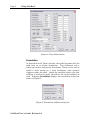
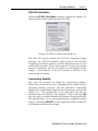
Solution Controls
Selecting Solution Controls displays the dialog box shown in
Figure 8. The user can either select a SafeRoof Linear Analysis,
SafeRoof User's Guide, Release 2.0
Page 10
Using SafeRoof
which performs a large displacement, elastic analysis of the
design, or a FMA3D Dynamic Analysis, which performs a
dynamic, large displacement, elastic plastic analysis. If the
SafeRoof Linear Analysis is selcted, the user then selects the
pressures for which the solution is desired: zero, bottom uplift,
top angle yield, yield at the bottom joint, peak combustion
pressure, or user specified. The user also specifies whether to
include buckling effects in the roof and floor.
If the dynamic analysis is selected, the user can select either to
specify a ramp loading or a combustion analysis, in a
combustion calculation will first be performed and then the
dynamic combustion pressure loads used in the analysis.
Figure 8: Solution controls dialog box
A zero pressure analysis does not have any internal pressure,
but the tank will be loaded by gravity loads on the tank (floor,
shell, roof, dead weight, and anchor) and the gravity load of any
liquid in the tank. For the FMA3D analysis option, the zero
pressure analysis is performed and used as the initial condition
for the dynamic analysis.
If the SafeRoof Linear Analysis option is selected the user can
specifically specify which pressure solutions they desire (uplift,
top angle yield, etc). For the FMA3D analysis option, a
transient analysis is performed using the zero pressure state as
an initial condition. The transient analysis results are scanned
to identify which failure conditions were met and the user can
then plot those results.
SafeRoof User's Guide, Release 2.0
Using SafeRoof
Page 11
For both static or dynamic analyses, the conditions are
identified as:
•
Uplift analysis is defined as the pressure to just cause
uplift of the shell.
•
Top angle yield is the pressure that causes yielding in the
top angle. Again, gravity loads are included.
•
Bottom joint yield os the pressure necessary to cause
yielding at the bottom joint (including gravity loads).
For only the elastic analysis, the peak pressure analysis is
performed using the combustion model. For this case, the
pressure to cause yielding at the top angle is first calculated. A
combustion analysis is then performed. If the pressure during
combustion exceeds the pressure to yield the top angle, the
combustion analysis proceeds with a top failure analysis also
included. The final result is calculated at the peak pressure,
while combustion is occurring, but before venting at the roof
lowers the tank pressure.
Finally, for an elastic analysis, the user may specify a pressure
for the analysis.
Results will be stored in a data file and available for
postprocessing.
Liquid Level
It is not necessary that the liquid level used for analysis be the
same as used for design. In fact, yielding of the bottom joint
typically occurs at lower pressures for lower liquid levels.
Selecting Liquid Level allows the user to change the value used
for analysis. The default value is the design value.
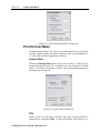
Combustion Parameters
If the user has selected an analysis that requires a coupled
combustion calculation, the user can modify the combustion
parameters. Selecting Combustion Parameters displays the
dialog box shown in Figure 9.
SafeRoof User's Guide, Release 2.0
Page 12
Using SafeRoof
Figure 9: Combustion parameters dialog box
In this dialog box, the user can select different fuels and the
location of the ignition. The most rapid pressure rise in the tank
will occur if the ignition source is far from the wall, roof, and
liquid. If the combustion front contacts any of these surfaces,
the volume of gas participating in the combustion is reduced.
Begin Calculation
Selecting Begin Calculation starts the calculations.
SafeRoof User's Guide, Release 2.0
Using SafeRoof
Page 13
API 650 Calculation
Selecting API 650 Calculation provides a dialog box (Figure 10)
that gives the results predicted using API 650.
Figure 10: API 650 calculation dialog box
The API 650 results include the API 650 maximum design
pressure, the API 650 predicted uplift pressure, the API 650
frangible joint failure pressure and the compression area at the
roof-to-shell junction. Since wind moment is used in the design
pressure calculation, the user can either use the default of zero,
supply a wind moment, or use the moment as defined in the
overturning calculation.
Overturning Stability
The user can evaluate the design for overturning stability.
When this is selected, the user is prompted for the wind velocity,
operating internal pressure, and the additional overturning
moment due to additional exposed area of structures on the tank
(Figure 11). The moment due to the tank shell and roof are
automatically calculated by the program. After selecting OK,
the user will be advised whether the present design meets API
650 specifications. If not, the program gives a suggested anchor
design. Selecting ACCEPT on the suggested anchor dialog box
will add the anchors to the design.
SafeRoof User's Guide, Release 2.0
Page 14
Using SafeRoof
Figure 11: Overturning Stability dialog box
POSTPROCESS MENU
Postprocessing allows the user to examine previously calculated
results, either results for which analyses were just performed or
to access the results of previous analyses.
Access Data
Selecting Access Data allows the user to select a data set for
postprocessing (Figure 12). Available sets are indicated in black
type. As soon as a selection is made, the corresponding pressure
and time are displayed.
Figure 12: Access data dialog box
Plot
After a data set has been selected, the type of plot desired is
indicated by selecting Plot. In the plot dialog box (Figure 13),
SafeRoof User's Guide, Release 2.0
Using SafeRoof
Page 15
the user can select the plot type: tank design, finite element
mesh,
pressure
time-history
(if
appropriate),
nodal
displacements, or element stresses. If element stresses are
selected, the user specifies the surface and stress component to
be plotted. Finally, the user specifies whether the plot should be
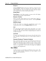
sent to the screen (window) or to the printer. Selecting OK,
generates the plot, as shown in Figure 14.
Figure 13: Plot data dialog box
Figure 14: Typical plot
SafeRoof User's Guide, Release 2.0
Page 16
Using SafeRoof
Zoom In
Selecting Zoom In allows the user to indicate a region for more
detailed display. The user indicates one corner with a mouse
click, defining the box by moving the mouse with the mouse
button depressed, and then releasing the button.
Zoom Reset
Zoom Reset is used after zooming to return to the full display
with automatic scaling of displacements.
Reverse Contour
There are times when stresses can be viewed more clearly by
reversing the direction of the stress contours. Selecting Reverse
Contour does this.
Displace Scale
If the user wants to control the magnification used in the
displacement plots, selecting Displace Scale allows this.
List
The user may list results to the screen, the printer, or to a file
by selecting List. This is useful for documentation or for saving
results to a file that then allows incorporating the results in
another document.
List Font
To have a well formatted list, the user can select the font for the
list. Selecting a fixed-pitch font (e.g. Courier) aligns columns of
the list.
Dynamic Display of Transient Analysis
For a transient analysis, the user can hold down the Cntrl and
Shift keys and then select the right or left arrows to move
forward or backward in time. This can create a “movie” of the
results. It is recommended that the user first set the Displace
Scale to an appropriate value so that all images are displayed
with the same magnification.
HELP MENU
SafeRoof makes use of the Microsoft Windows help system. The
user can obtain further information on most aspects of the
program from the help file.
Index
SafeRoof User's Guide, Release 2.0
Using SafeRoof
Page 17
Selecting Index shows an index of the help available and allows
the user to search for keywords.
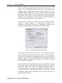
Using Help
Explains how to use the help functions.
SafeRoof User's Guide, Release 2.0
Page 18
Using SafeRoof
About
Gives information about the version of SafeRoof.
SafeRoof User's Guide, Release 2.0
Example Problem
19
EXAMPLE PROBLEM
This section provides an example problem. The user can follow
this example to help understand the use of the program. It is
assumed that the user has installed SafeRoof and is familiar
with Windows. In the following discussion, menu selections are
capitalized and typed user responses are underlined.
STEPS
1. Begin running SafeRoof by double-clicking on the SafeRoof
icon.
2. Select FILE/NEW and give example1 as the file name.
3. Select DESIGN/AUTO DESIGN.
design dialog box.
This displays the auto
4. This dialog box allows the user to specify all details of a tank
needed for design. We will leave most of the parameters at
their default values. By using the tab key or with the mouse,
change the tank diameter to 60 feet and the tank height to
40 feet, then select the OK button. A warning box will
appear stating that the liquid level for design is suspiciously
low (by default 35 feet and the height is now 40 feet).
Similar checks are made for several parameters to help
ensure a valid design. Select OK to continue.
5. SafeRoof will now display a design that meets API 650 rules
for frangible joints. We will continue with this design,
however the user could select DESIGN/USER SPECIFIED to
change the design.
6. Select ANALYSIS/SOLUTION CONTROLS.
the analysis controls dialog box.
This displays
7. Using the mouse, select pressures of Zero, Bottom Uplift,
Yielding Top Angle, Yielding Bottom. This means SafeRoof
will calculate stresses at these four pressures. Since the
uplift and yielding pressures are not known, this will require
iteration to determine these values. Select OK to continue.
8. Select ANALYSIS/LIQUID LEVEL to specify the liquid level
for analysis. By default the analysis level is one foot below
the top angle or the user defined design value, whichever is
smaller. Note that some free space must be available in the
tank if a combustion analysis is to be performed. In this
example, change the liquid level to 10 feet and then select
OK.
SafeRoof User's Guide, Release 2.0
Page 20
Example Problem
9. Select ANALYSIS/BEGIN CALCULATION to start the
calculations. SafeRoof will solve for each of the pressures.
Because the problem is nonlinear (large deformation and
contact on the bottom), each solution is iterative. In addition
there is a larger iteration loop when determining the
pressures for yielding and uplift. This is the reason for the
iterations displayed during the solution process. When each
requested solution is completed, a file with the solution data
is written. On a 25 MHz 486 computer, the zero pressure
solution takes about 2 minutes, the uplift pressure solution
takes 3 minutes, the top yield solution takes 6 minutes, and
the bottom yield solution 22 minutes.
10. At
the
completion
of
the
analysis,
select
POSTPROCESS/ACCESS DATA to examine results. The
data access dialog box allows the user to select from the
available data sets for plotting. For this example, we have
four data sets available: zero pressure, bottom uplift, yielding
top angle, and yielding bottom. Only one set can be accessed
at a time, however, as you click on each selection box, the
pressure and time corresponding to the data set is displayed.
For this example, the bottom uplift pressure is 0.385 psi, the
yielding top angle pressure is 0.452 psi, and the yielding
bottom pressure is 1.366 psi. Thus, we would expect a small
amount of uplift before failure initiation at the top angle, but
there is a large margin before yielding at the bottom occurs.
For illustration, select the yielding top angle data set, then
OK.
11. For each data set, the user can plot the design,
displacements, and stresses. To indicate the type of plot
desired, select POSTPROCESS/PLOT. This displays the
plotdata dialog box. Select Nodal Displacement then OK.
This will make a displacement plot.
12. Use POSTPROCESS/ZOOM IN to examine a region more
closely.
13. Use POSTPROCESS/DISPLACE SCALE to change the
displacement scale.
14. Use POSTPROCESS/ZOOM
displaced mesh.
RESET
to
view
the
full
15. Select POSTPROCESS/PLOT to change the variable being
plotted. From the plot data dialog box, select Element
Stress, Middle Surface, Equivalent Stress to see the stresses
in the tank. This creates a color stress contour display.
SafeRoof User's Guide, Release 2.0
Example Problem
21
16. Select POSTPROCESS/LIST to list selected data to the
screen or to a file. To improve the appearance of the list,
select a non-proportional font (such as courier) using
POSTPROCESS/LIST FONT.
17. Select FILE/EXIT to exit SafeRoof.
SafeRoof User's Guide, Release 2.0
Page 22
Theory and Implementation
THEORY AND IMPLEMENTATION: STATIC
ANALYSIS
This describes the theory and implementation for the SafeRoof
static, large deformation, elastic analysis capability.
AUTOMATIC DESIGN
The automatic design option allows the user to input basic tank
parameters, SafeRoof will then automatically design a tank to
API 650 rules. Two automatic design options, API 650 Section 3
and Appendix F, are available. The basic design parameters are
input by the user of the program. The following assumptions
are made for the auto-designed tanks:
1.
2.
3.
4.
5.
3/16 inch thick roof plate supported by rafters,
Roof slope 3/4 : 12 inches,
Top angle does not overlap top shell,
Bottom plate (or annular bottom plate if there is one)
projects two inches beyond the shell,
Shell thickness calculated by one foot method or Appendix
A method.
The tank is assumed to rest on a sand foundation with a default
modulus of 250 lb/in2/in. A ringwall with a default modulus of
1000 lb/in2/in and 6 inches width, measured from the tank shell,
is also assumed.
The design can be checked for overturning stability due to a
wind velocity of 100 miles per hour (or user specified value) and
anchors will be designed if necessary.
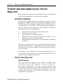
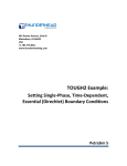
STRUCTURE ANALYSIS
Shell Elements
The roof, shell, and bottom of the tank are modeled using
axisymmetric conical shell elements, as shown in Figure 15.
The element (Zienkiewicz, 1991) has constant thickness with
three degrees of freedom at each node: translations in the nodal
x and y directions and a rotation about the nodal z axis. The
element has membrane and bending capabilities, as well as
large deflection capability.
SafeRoof User's Guide, Release 2.0
Theory and Implementation
I
Z
s
y,w
L
φ
r
Page 23
R
Θ,z,v
J
x,u
Figure 15: Axisymmetric shell element
The motion, un , of a general point in the element is:
⎧u⎫
un = ⎨ ⎬
⎩w ⎭
(1)
where u and w are the in-plane and lateral displacements,
respectively. The circumferential displacement v is identically
zero due to axisymmetry. The strain at a point is a function of
the displacement:
⎧ ∂u 1 ⎛ ∂w ⎞ 2 ⎫
⎧
∂2 w ⎫
−
+
⎪
⎪
⎜
⎟
⎪
⎪⎪
⎧ε x ⎫ ⎪
⎪
∂x 2 ⎪⎬
ε = ⎨ ⎬ = ⎨ ∂x 2 ⎝ ∂x ⎠
⎬ + y⎨
⎩ε y ⎭ ⎪ 1 ( u sin φ − w cos φ )⎪
⎪− sin φ ∂w ⎪
⎪⎩
⎪⎩ r
⎪⎭
r ∂x ⎪⎭
= A un
(2)
A is an operator matrix defined in equation (3) where the
subscripts c, y, and l represent the center surface, bending and
large deformation effects, respectively.
A = Ac + Ay + Al
⎡ ∂
⎢
= ⎢ ∂x
sin φ
⎢⎣
r
⎤
⎤ ⎡
∂2
0
⎥ ⎡ 0 1 ∂w ∂ ⎤
⎥ ⎢
2
∂x
+
+⎢
y
2 ∂x ∂x ⎥
cos φ ⎥ ⎢
sin φ ∂ ⎥ ⎢
⎥⎦
0
⎥ ⎣0
−
⎥ ⎢0 −
r ⎦ ⎣
r ∂x ⎦
0
(3)
SafeRoof User's Guide, Release 2.0
Page 24
Theory and Implementation
For a linear material, the stress-strain relation has the form:
σ = Dε
=
E
1− ν 2
⎡ 1 ν ⎤ ⎧ε x ⎫
⎢ν 1 ⎥ ⎨ε ⎬
⎦⎩ y ⎭
⎣
(4)
Using cubic shape functions for lateral displacement and nodal
rotation and linear shape functions for in-plane displacement,
the motion of a point un can be interpolated in terms of nodal
displacement ul:
u n = N ul
⎡ 0
=⎢ I
⎣ N1
N 3I
0
0
0
N 2I
N1J
N 3J
0
⎧wI ⎫
⎪u ⎪
⎪ I⎪
0 ⎤⎪ β I ⎪
⎥⎨ ⎬
N 2J ⎦⎪w J ⎪
⎪uJ ⎪
⎪ ⎪
⎩ βJ ⎭
(5)
where β is the rotation at the node and the shape functions are:
1 s
− (3 − s 2 )
2 4
1 s
N1J = + (3 − s 2 )
2 4
L
N I2 = (1 − s 2 )(1 − s)
8
L
N 2J = − (1 − s 2 )(1 + s)
8
1
N3I = (1 − s)
2
1
N 3J = (1 + s)
2
N1I =
(6)
The nodal displacements in the local coordinate system can be
written in terms of the global system using the following
transformation:
SafeRoof User's Guide, Release 2.0
Theory and Implementation
Page 25
u l = Tr u e
⎡cos φ
⎢ sin φ
⎢
⎢ 0
=⎢
⎢ 0
⎢ 0
⎢
⎣ 0
sin φ
0
0
− cos φ
0
0
0
1
0
0
0 cos φ
0 sin φ
0
0
0
0
0⎤ ⎧u XI ⎫
⎪ ⎪
0
0⎥ ⎪ u ZI ⎪
⎥
0
0⎥ ⎪⎪ β I ⎪⎪
⎥⎨ ⎬
sin φ 0⎥ ⎪u XJ ⎪
− cos φ 0⎥ ⎪ u ZJ ⎪
⎥⎪ ⎪
0
1⎦ ⎪⎩β J ⎪⎭
0
(7)
The strain-nodal displacement relation can now be written as:
{ε} = ANu l
= ( A c + yA y + A l )Nu l
(8)
= (B c + yB y + B l )u l
Assuming a linear material, the total strain energy is the strain
energy density integrated over the volume:
U=
∫
vol
1
σ : ε d(vol)
2
(9)
The work done by an external force is the product of force and
displacement:
V = F ⋅ u = uT
∫N
T
f d( vol )
(10)
vol
where f is the external loading on the element. By applying
Hamilton's principle, the shell has the following governing
equation:
δ( U + V ) = δu T Ku − δu T F = 0
(11)
where the global stiffness matrix K is the integration over the
entire volume:
K=
∫ (B
c
+ B l +B y ) T D ( B c + B l + B y ) d( vol )
(12)
vol
SafeRoof User's Guide, Release 2.0
Page 26
Theory and Implementation
When integrating through the thickness of a conical shell, a
cos φ
factor (1 + y
) needs to be included. For any constant H, we
r
have:
∫
t/ 2
H(1 + y
− t/ 2
cos φ
)dy = Ht
r
cos φ
t 3 cos φ
∫− t/ 2 H(1 + y r )ydy = H 12 r
t/ 2
cos φ 2
t3
∫− t/ 2 H(1 + y r )y dy = H 12
t /2
(13)
The element stiffness matrix in local coordinates is:
Kl =
∫ tB
T
c
DB c d(area )
area
t 3 cos φ T
B c DB y + B Ty DB c d(area )
+ ∫
area 12 r
t 3 cos φ T
B c DB y + B Ty DB c d(area )
+ ∫
12
r
area
t3 T
B y DB y d(area )
+ ∫
area 12
+
∫ t( B
area
+
∫
area
T
c
(
)
(
)
DB l + B Tl DB c + B Tl DB l ) d(area )
t 3 cos φ T
( B y D B l + B lT D B y ) d(area )
12 r
(14)
The element stiffness matrix in global coordinates will be:
K e = TrT K l Tr
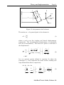
(15)
As is shown in Figure 16, the loads considered are gravity loads,
F1, pressure loads, F2, and the secondary effect of pressure load,
F3. The reaction force from the elastic foundation will be
converted to stiffness and will be discussed later.
F = F1 + F2 + F3
For an element, the gravity load in local coordinates is:
SafeRoof User's Guide, Release 2.0
(16)
Theory and Implementation
Page 27
⎧ ρg cos φ ⎫
L
⎬ dx
f1 l = −2π t ∫0 r N T ⎨
⎩− ρg sin φ ⎭
(17)
The element pressure loading vector in local coordinate is:
⎧ 0 ⎫
L
⎬ dx
f 2 l = −2π ∫0 r N T ⎨
⎩ p1 − p 2 ⎭
(18)
The normal stress due to pressure converted to strain in the
plane of the shell has the form:
ε pr = −
⎧1⎫ ν y
⎧1⎫
ν
( p1 + p2 )⎨ ⎬ −
( p2 − p1 )⎨ ⎬
2E
⎩1⎭ 2E t
⎩1⎭
(19)
The equivalent load vector is:
f3l = ∫vol B T D ε pr d( vol )
(20)
I
p2
p2
φ
J
Figure 16: Loading on element
Foundation Elements
Foundation elements are used to represent the nonlinear
reacting forces on the bottom of the tank by the foundation. The
foundation of the tank is modeled as an elastic interface without
friction.
The total surface traction force in the global coordinate can be
written as an integral over the entire surface:
Fe = ∫ N T t dS
(21)
S
SafeRoof User's Guide, Release 2.0
Page 28
Theory and Implementation
where t is the surface traction in global coordinate. For an
element, the surface traction in local coordinates can be
obtained by the following transformation:
t = RT t n
⎡ cos φ sin φ 0⎤
⎢
⎥
= ⎢sin φ − cos φ 0⎥ t n
⎢⎣ 0
0
1 ⎥⎦
(22)
where R is the coordinate transformation matrix. The local
surface traction and local displacement has the relation:
t n = − Tu n
⎡0 0 ⎤ n
= −⎢
⎥u
⎣0 k f ⎦
(23)
where
⎧ 0
kf = ⎨
⎩stiffness of foundation
when interface open
when interface closed
Substituting equations (5), (22) and (23) into (21), gives the
foundation force vector and foundation stiffness matrix:
F e = −K e u l
= − ∫S N T R T TRN dS u l
K e = ∫S N T R T TRN dS
(24)
(25)
The foundation stiffness matrix is evaluated every iteration and
added to the global stiffness matrix.
SafeRoof User's Guide, Release 2.0
Theory and Implementation
Page 29
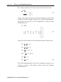
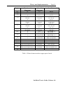
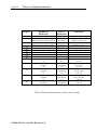
Finite Element Mesh Generation
The tanks considered in this program are assumed to be at least
5.0 feet in diameter with two shell courses at least 2.5 feet high.
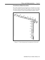
The finite element mesh used for modeling the tank is generated
as shown in Figure 17 and 18 and described in Tables 1 and 2.
N7
N6
N5
N4
N3
N2
N1
N10
N11
N9
N8
N12
N13
N14
N15
N16
Figure 17: Finite element mesh on upper part of the tank
SafeRoof User's Guide, Release 2.0
Page 30
Theory and Implementation
N16
N17
N18
N19
N20
N21
N29
N28
N27
N26
N25
N24
N23
N22
Figure 18: Finite element mesh on lower part of the tank
SafeRoof User's Guide, Release 2.0
Theory and Implementation
Page 31
Region
Number of
Elements
Size of
Elements
Condition
N1
N2
N3
12
12
(R-18)/2
6
0
(R-30)/3
6
0
(R-48)/4
12
0
(R-96)/6
10
0
(R-156)/12
2
2
Angle Width -1
1
2 x Angle Width
1
12
12
6
6
(Top course height-30)/3+1
0
(Top course height-48)/2+1
10
0.5
1.0
Calculated
2.0
Calculated
3.0
Calculated
4.0
Calculated
6.0
Calculated
0.5
1/3 Angle Width
0.5
1/3 Angle Width
0.5
2 x Shell Thick
0.5
1.0
2.0
4.0
Calculated
Calculated
Calculated
Always
Always
24 < R < 33
33 < R
R < 33
33 < R < 52
52 < R
R < 52
52 < R < 102
102 < R
R < 102
102 < R < 168
168 < R
R < 168
168 < R
Angle Width > 1
Angle Width < 1
Angle Width > 1
Angle Width < 1
Angle not overlap shell
Angle overlap shell
Always
Always
Always
Top course height > 48
102 < R < 168
Top course height < 48
Top course height > 48
All intermediate courses
N4
N5
N6
N7
N8
N9
N10
N11
N12
N13
N14
N15
N16
Table 1: Finite element mesh on upper part of tank
SafeRoof User's Guide, Release 2.0
Page 32
Theory and Implementation
Region
Number of
Elements
Size of
Elements
Condition
N16
N17
10
0
(Bottom course height-48)/2+1
6
(Bottom course height-48)/3+1
6
12
12
2
12
12
(R-18)/2
6
0
(R-30)/3
6
0
(R-48)/4
12
0
(R-96)/6
10
0
(R-156)/12
Calculated
Calculated
4.0
Calculated
2.0
1.0
0.5
Calculated
0.5
1.0
Calculated
2.0
Calculated
3.0
Calculated
4.0
Calculated
6.0
Calculated
All intermediate courses
Bottom course < 48
Bottom course > 48
Bottom course < 48
30 < Bottom course < 48
Always
Always
Always
Always
Always
Always
24 < R < 33
33 < R
R < 33
33 < R < 52
52 < R
R < 52
52 < R < 102
102 < R
R < 102
102 < R < 168
168 < R
R < 168
168 < R
N18
N19
N20
N21
N22
N23
N24
N25
N26
N27
N28
N29
Table 2: Finite element mesh on lower part of tank
SafeRoof User's Guide, Release 2.0
Theory and Implementation
Page 33
Nonlinear Solution Procedure
At the start of the structural analysis, the finite element model
is meshed and a linear stiffness matrix formed. For the
specified pressure, a global loading vector is obtained and saved.
After each iteration, part of the newly obtained displacement
will be added to the previous one as the next estimate of the
solution. The nonlinear part of the stiffness matrix (due to the
large deflection and elastic foundation) are evaluated using the
new solution and then used for the next iteration. If available, a
previous solution is used as the first guess. The algorithm can
be written as:
do{
U /n = ( K 0 + K nl −1 ) −1 F
U n = (1 − α )U n −1 + αU /n
K nl = K nl ( U n )
while( U n − U n −1
∞
≤ 0.001 U n
∞
)
(26)
where:
U n/ = new calculated displacement vector
Un = displacement vector after n-th iteration
K nl = nonlinear portion of stiffness after n-th iteration
K0 = linear portion of stiffness, constant for a given mesh
F = global loading vector, constant for a given pressure
α = relaxation coefficient, changes between 0.05 to 0.5
If the yielding pressure calculation is required for the top joint, a
trial pressure will be used first.
After the converged
displacement has been calculated, the mean equivalent stress at
the entire horizontal part of the top angle is calculated and
compared to the yielding stress of the material. A new trial
pressure is found by Newton’s method for the next pressure step
until the calculated stress is within ± 0.5% of the yielding stress.
The calculation of bottom yield pressure is similar to that of top
yield. The equivalent stress is checked for both shell and bottom
elements near the joint and the maximum element stress is
compared to the yielding stress.
SafeRoof User's Guide, Release 2.0
Page 34
Theory and Implementation
Due to the nonlinearity of the elastic foundation at the bottom,
Newton’s method does not give a reliable estimate of the bottom
uplift pressure while doing the large iteration loop to determine
that pressure. An assumed upper and lower bound of pressure
is tried first and a new trial pressure is found by reducing the
searching region by half. The calculation is completed when the
vertical displacement of the bottom joint node is less than 1% of
that of the node at the center of the tank bottom or the pressure
between the upper and lower bounds is less than 0.02 psi.
To find a peak pressure in the tank during combustion, the top
yield pressure is first calculated. Then a combustion analysis is
performed with venting beginning when the top yield pressure is
reached. The combustion calculation finishes when the pressure
in the tank reduces to zero due to venting. The peak pressure
during the combustion process is used for the peak stress
calculation.
After each set of calculations is done, the displacement, finite
element mesh, and other analysis parameters are written to a
solution file along for use during post-processing.
COMBUSTION ANALYSIS
Solution Procedure
The pressure rise in the vapor space inside the tank is
calculated by evaluating combustion in small increments of
time. The flame front is assumed to grow in a spherical fashion
originating from a point source ignition in the tank. The volume
of reactants burned in a given time increment is used to
determine the pressure after each time increment. To evaluate
this pressure, the speed at which the flame front moves is
multiplied by a time increment, giving a distance. From this
distance, an incremental volume is calculated. This volume is
then burned at constant volume combustion and allowed to
expand until the pressure inside the tank is uniform.
To calculate the pressure rise during a time increment, an
adiabatic flame temperature is calculated for the flame front,
assuming constant volume combustion and chemical
equilibrium. The pressure inside the volume swept out by the
flame front, during a single time increment, increases due to the
burning of the reactants at constant volume. The volume swept
by the flame front is then allowed to expand, causing the
SafeRoof User's Guide, Release 2.0
Theory and Implementation
Page 35
reactants and products to compress, with no mixing, until the
pressure inside the tank is uniform. After the pressure inside
the tank is balanced, time is incremented and the process
repeated. When the internal pressure reaches the roof-to-shell
joint yielding pressure, a venting calculation starts and part of
the combustion products are vented, reducing the pressure. The
peak pressure found during the combustion calculation and is
used for the structural calculation. The combustion calculation
continues until the pressure in the tank is reduced to
atmospheric pressure.
In these calculations, the tank is assumed to be adiabatic and
the tank rigid. The analysis also neglects radiation heat
transfer between the flame front and wall of the tank.
SafeRoof User's Guide, Release 2.0
Page 36
Theory and Implementation
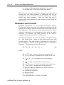
Combustion Wave Geometry
This analysis assumes that the combustion wave will burn as a
radial deflagration, having a smooth spherical shaped flame
front from a point source ignition.
The flame front is assumed to grow in a spherical fashion
originating from a point source ignition in the tank. As the
flame front burns across the reactants, the products formed will
occupy the volume inside the flame front, and are not allowed to
mix with the reactants. If the ignition source is not in contact
with the tank or the fluid being stored and the time duration
from the ignition is small, the volume is a sphere. Otherwise
the fireball will be constrained by the tank or liquid in the tank.
Numerical integration is necessary to calculate the volume of
the fireball with sufficient accuracy.
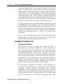
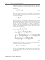
Consider a tank of radius R with height of vapor space H as
shown in Figure 19.
SafeRoof User's Guide, Release 2.0
Page 37
Theory and Implementation
A
θ ο ρο
B
D O
F
α
E
G
R
C
Z
h
H
O
e
z
r
ρο
Figure 19: Geometry of fireball at position z
The ignition source is located at point O, which is distance e
away from center line of the tank shell and distance h below the
roof of the tank. At a given instance, the radius of the fireball is
r. Using a cylindrical coordinate system with the origin at the
ignition source and the z axis up, the cross section area of the
SafeRoof User's Guide, Release 2.0
Page 38
Theory and Implementation
fireball S at height z can be determined analytically. The total
volume of the fireball V can be obtained using the following
integration:
V = ∫max( h − H , − r ) Sdz
min( h , r )
(27)
When the ignition source is on the centerline of the tank, the
value of e equals zero and the cross section at any z location will
be a circle with radius :
ρo = r 2 − z 2
(28)
When e is not zero, the calculation of cross sectional area can be
performed for three cases. When the fireball and the tank shell
do not touch each other for the given z, the cross sectional area
is that of a circle with radius r, as given in equation 28.
Otherwise, the cross sectional area is the common part of two
circles. For a fireball as shown in Figure 19, the total cross
section area S at height z is:
R 2 − e2 − r2 + z2
S = ( r − z ) cos (
)
2e
⎡
( r2 − z2 + e2 − R 2 )2 ⎤
2
−1 1
2
2
⎥
r −z −
+ R sin ⎢
4e 2
⎣R
⎦
2
−1
2
( r2 − z2 + e2 − R 2 )2
− r −z −
4e 2
2
2
R 2 − e2 − r2 + z2
+
2e
( r2 − z2 + e2 − R 2 )2
R −r +z +
4e 2
2
2
2
( r2 − z2 + e2 − R 2 ) 2
r −z −
4e 2
2
2
(29)
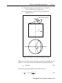
Equation (29) is valid for α < π/2, that is, cross section with z
coordinate satisfies the following relations:
( R − e)2 < r2 − z2 < R2 + e2
(30)
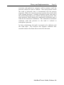
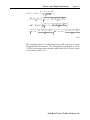
In case of α is bigger than π/2, the geometry of the cross section
is shown in Figure 20. In this case, the total area of the cross
section will be:
SafeRoof User's Guide, Release 2.0
Theory and Implementation
Page 39
⎛ r2 − z2 + e2 − R 2 ⎞
S = ( r 2 − z 2 ) cos −1 ⎜
⎟
⎝ 2e r 2 − z 2
⎠
R 2 − e2 + z2 − r2
( r2 − z2 + e2 − R 2 ) 2
r2 − z2 −
2e
4e 2
⎡1
( r2 − z2 + e2 − R 2 )2 ⎤
⎥
+ π R 2 − R 2 sin −1 ⎢
r2 − z2 −
4e 2
⎣R
⎦
+
( r2 − z2 + e2 − R 2 )2
+ r −z −
4e 2
2
2
( r2 − z2 + e2 − R 2 )2
R −r +z +
4e 2
2
2
2
(31)
The calculated area S is then integrated with respect to z using
Runge-Kutta-Gill method. The integration step length is set to
1/150 of total vapor space height, which will give an error equal
or less than 4.2 x10⁻¹⁰ r 5.
SafeRoof User's Guide, Release 2.0
Page 40
Theory and Implementation
A
O
B
β
θο
E
F
D
C
Z
h
H
G
e
z
r
ρο
Figure 20: Geometry of the Fireball at Position z
when R 2 + e 2 < r 2 − z 2 < ( R + e) 2
Burning Velocity
The combustion process is assumed to be a deflagration, where
the burning velocity starts at the laminar velocity and
accelerates as a function of the temperature, pressure, and level
of turbulence inside the tank. The speed of the flame front as
observed from a stationary coordinate has the following form:
SafeRoof User's Guide, Release 2.0
Theory and Implementation
Page 41
0.5
Tk
⎡
−0.2 ( ) 0.75 ⎤
P
T
τs
⎥ ( u ) −0.04 ( u ) 2 ( −2.614 + 7.288Φ − 3.614Φ2 )
S = U t ⎢1 − e
T0
⎢⎣
⎥⎦ Po
(32)
Where:
S = flame speed (m/s),
Pu = reactant pressure (Pa),
Po = initial pressure (Pa),
Tu = reactant temperature (K),
To = initial temperature (K),
Ut = fully developed turbulent burning flame speed (m/s),
Tk = elapsed time from ignition (s),
τs = integral time scale (s),
Φ = equivalence ratio, defined as the actual mass air-fuel
ration divided by the stoichiometric air-fuel ratio.
The above expression for the burning velocity allows for
variation of the fuel type, equivalence ratio, temperature,
pressure, and changes in turbulence levels of the reactants.
Venting
The venting calculation starts when the roof-to-shell joint
reaches yielding (failure initiation). A venting mass flow rate is
calculated and the total mass that has left the tank during the
time step is used to determine the pressure drop due to venting
for that given time step. The mass flow rate of the combustion
products is calculated assuming constant pressure and
temperature inside the tank for the time increment. The
pressure and temperature are then recalculated based on the
amount of mass that is left inside the tank.
For venting during frangible joint failure, a simplified analysis
assuming adiabatic incompressible open-channel flow through a
sluice gate is made. For a known roof-to-shell joint opening area
the volume flow rate though the opening is given by the
following equation:
Q = Cd A
where
2P
ρ
(33)
Cd = coefficient of contraction, between 0.6 to 0.9
P = pressure difference
SafeRoof User's Guide, Release 2.0
Page 42
Theory and Implementation
ρ = density of the combustion products to be vented
A = opening area of the roof-to-shell joint failure
With the time increment small, the change in pressure due to
venting over the time increment is sufficiently low for the
temperature to be assumed to remain constant for venting
during each time increment. After the mass flow rate is
calculated for each time step, a new pressure is found using the
ideal gas law.
FRANGIBLE JOINT FAILURE
Frangible joint failure is a very complicated dynamic process.
The fracture of the joint vents the combustion products out the
opening, reducing the pressure distribution on the tank roof and
shell with time. The geometry of the tank during joint failure
cannot be described by an axisymmetric shell model or simple
formulas. To estimate the peak pressure in the tank, a
simplified frangible joint failure model is used.
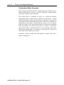
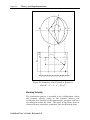
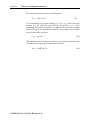
After failure initiation, the roof of the tank is assumed to rotate
as a flat plate about a point on the roof-to-shell joint with
rotation angle φ. The vent opening is assumed only over part of
the circumference defined by the opening angle θ, as shown in
Figure 21. The moments acted on the roof are:
Mw + Mi + Mr + Mf + Mm − Mp = 0
(34)
where:
M p = π R 3 P cos φ = moment due to pressure the roof,
M w = ρ g t h π R 3 cos φ = moment due to weight of the roof,
7
M r = π ρair φ& 2 c D R 5 = moment due to air resistance,
8
5
&& = moment due to inertia force,
M i = π ρth R4 φ
4
M f = 2 F R 2 cos φ ( π − θ − sin θ) = moment due to edge force,
M m = 2 m j R sin θ = moment due to edge moment,
P = pressure difference between two sides of the roof,
th = thickness of the roof,
g = acceleration of gravity,
ρ = density of steel,
rair = density of air,
Cd = drag coefficient (1.143 for a flat disk),
SafeRoof User's Guide, Release 2.0
Theory and Implementation
Page 43
F = downwards force acted on the roof, obtained at
roof-to-shell joint yield pressure,
mj = edge moment, obtained at roof-to-shell joint
yield pressure.
Mw+Mi+Mr+Mf+M
Mp
φ
R
θ
Figure 21: Forces acting of roof during venting
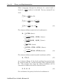
When the roof has rotated an angle φ while the opening has an
angle θmax at a given instant, the maximum opening height is:
y max = 2 R sin φ
(35)
Assume the opening width as the function of θ is:
y=
⎡
⎛ θπ ⎞ ⎤
1
y max ⎢1 + cos⎜
⎟⎥
2
θ
⎠⎦
⎝
max
⎣
(36)
SafeRoof User's Guide, Release 2.0
Page 44
Theory and Implementation
The total opening area can be calculated as:
A open = R y max θ max
(37)
It is reasonable to say that when φ = 0, θmax = 0, and if the roof
rotates φ = π/2 then the roof will fly off and θmax = π. Also
assuming that when φ equals or is larger than π/4, the opening
area will reach its maximum possible value, (the cross section
area of the tank), we have:
θ max = π sin φ
(38)
The opening area can then be written as a function of φ only and
calculated in each step of combustion analysis.
A open = 2πR 2 sin 2 φ
SafeRoof User's Guide, Release 2.0
(39)
Theory and Implementation
Page 45
THEORY AND IMPLEMENTATION FMA-3D
ANALYSIS
This describes the dynamic, large displacement, elastic-plastic
analysis capability in SafeRoof. This was accomplished using
the FMA-3D code (Key, 2004). The following description of
FMA-3D is taken from the Theoretical Manual.
“The program is designed to compute the timedependent displacements, velocities, accelerations,
and stresses within elastic or inelastic, threedimensional bodies composed of arbitrary shapes
and materials. The program is a candidate for use
in applications either where large energies and
forces are present, where stress wave propagation
is occurring, or where large displacements and
strains dominate. Applications characterized by
small forces and in¯nitesimal strains are not
precluded, however. Applications for which the
programs of this class have seen use fall into the
areas of spent nuclear fuel shipping cask impact
studies, explosive and high-rate metal forming,
structures subjected to internal or external blast,
and buried structure survivability studies.
An accident is a typical situation requiring the
analysis of a structure's transient dynamic
response. Virtually every industry is faced with the
problem of accidents, either in terms of the plants
and facilities it operates or the products it designs.
Accident analyses focus on the worst case, the
unexpected, and the disabling situation. It is not
the normal operating loads which are considered,
but rather the extreme loads to which a structure is
to be subjected. The structure may no longer be
useful for its original purpose, but it should not
become part of a chain of events leading to damage
beyond that from the original stimulus. In these
cases, it is the large deformation, the sudden
dynamic excursions, and the inelastic material
behavior that need to be modeled.”
FMA-3D is distributed freely under the GNU license. To meet
GNU license requirements and still incorporate FMA-3D with
SafeRoof User's Guide, Release 2.0
Page 46
Theory and Implementation
SafeRoof, the approach taken was to modify SafeRoof so that the
use can select either a static analysis or a dynamic analysis. If a
static analysis is requested, then the internal SafeRoof solution
is used. If a dynamic analysis is requested, an input file for
FMA-3D is written and the FMA-3D calculation automatically
started. At the end of the FMA-3D analysis, the results are read
from the FMA-3D output files and plotted in SafeRoof. By
taking this approach, it was not necessary to make changes to
FMA-3D, while, to the user, the FMA-3D analysis appears
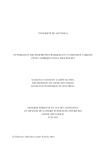
seamlessly integrated.
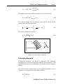
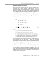
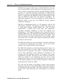
FMA-3D is implemented only as a 3D program, with no 2D
axisymmetric elements. The element used for the analysis was
a 4-node plate element (P4EL), Figure 22. The 3D model
represented a 5 degree slice of the tank, with appropriate
symmetry boundary conditions so that the response was
axisymmetric. All material properties were assigned from the
SafeRoof input data. The internal load of product in the tank is
represented by a linearly increasing pressure with depth. This
does not include any mass effects due to the product, which
would only serve to further slow uplift and bottom joint failure
and thus is conservative.
The FMA-3D model uses contact elements under the tank floor
to represent the deformation and uplift. At the roof, rafter
support is also modeled using contact elements.
The FMA-3D calculation is actually performed in two stages. In
the first calculation, all static loads including gravity and
product loads are applied to the model. A dynamic relaxation
run is then performed, where damping is included in the
analysis and the dynamic analysis is continued until static
equilibrium is reached. This gives a static solution in which the
tank has settled on its foundation and the roof is being
supported by rafters. The static equilibrium state is then used
as the initial condition for the transient analysis in which the
internal pressure loads are added.
The user has the option of specifying a linear ramp pressure
loading on the tank or using the SafeRoof combustion capability
to calculate the pressure load. The linear ramp can be used to
specify such a slow ramp that the tank response is essentially
static.
SafeRoof User's Guide, Release 2.0
Theory and Implementation
Page 47
Figure 22: 4-node plate element (FMA, 2004)
During post-processing, displacements at the floor and elements
at the top and bottom joints are monitored to identify the onset
of yielding and uplift. The time steps at which yielding occurred
are then available for plotting.
SafeRoof User's Guide, Release 2.0
Page 48
Verification Problem
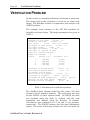
VERIFICATION PROBLEM
In this section, an example/verification calculation is presented.
The design used in the calculation is based on an actual tank
design. The SafeRoof solution is compared to both analytic and
ANSYS solutions.
The example tank conforms to the API 650 standard for
frangible roof joint design. The design parameters are given in
Table 3.
Diameter of the tank:
26.000
ft.
Height of the tank:
36.000
ft.
Roof slope:
0.750
inch in 12 inches
Thickness of roof plate:
0.1875
in.
Top angle width:
2.000
in.
Top angle thickness:
0.1875
in.
Top angle at outside of tank
Angle not overlap top shell
Number of courses:
4
Course
Height (in.)
Thickness (in.)
1
2
3
4
108.000
108.000
108.000
106.000
0.2500
0.2500
0.2500
0.1875
Thickness of bottom plate:
0.2500
in.
Bottom plate beyond shell:
2.00
in.
No annular bottom plate
Inner radius of ringwall:
12.500
ft.
Stiffness of ringwall:
1000.0
psi/in.
Stiffness of sand foundation:
250.0
psi/in.
Material of the tank plate:
ASTM A36
Minimum yielding strength:
36.00
ksi
Table 3: Parameters for verification problem
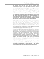
The SafeRoof finite element model has 240 nodes, 239 shell
elements and 61 interface elements. The same mesh was used
for the ANSYS 5.0 finite element model. In ANSYS, the shell
was modeled using the Shell 51 element and the tank
foundation was modeled using the Interface 12 element.
Calculations were performed at 0.1 psi and 1.0 psi pressure,
respectively. The ANSYS solution used the large deformation
option. The linear closed form solution was also calculated for
SafeRoof User's Guide, Release 2.0
Verification Problem
Page 49
the stresses near the top joint, with an annular ring
representing the angle. Since the linear closed form solution
does not include the gravity loading, its internal pressure was
reduced by 0.052 psi, which is the value required to overcome
the weight of the roof. Because of the nonlinear support at the
bottom, no analytic solution is available.
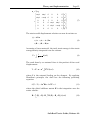
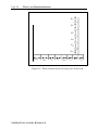
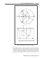
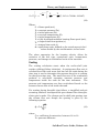
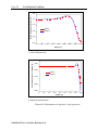
The calculated
displacements and stresses are plotted in Figures 22 through 25.
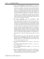
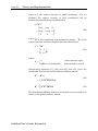
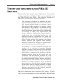
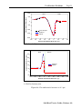
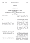
The verification calculations indicate that SafeRoof, ANSYS and
the linear closed form solution all give similar results at the
roof-to-shell joint when the internal pressure is low (Figure 23
and Figure 24). In this case, the deflections are small, so that
the nonlinear results are close to that of a linear analysis.
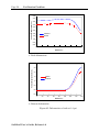
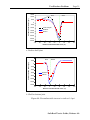
Under higher pressure, the nonlinear finite element solutions
give smaller stresses than that of linear analysis, as shown in
Figure 25 and Figure 26. SafeRoof gives somewhat larger
displacements than ANSYS, hence larger stresses result. Near
the roof-to-shell joint, the differences are not significant. At the
shell-to-bottom joint, SafeRoof gives larger uplift of the bottom
plate and larger stresses than given by ANSYS.
SafeRoof and ANSYS use somewhat different large deflection
formulations. The ANSYS finite element model is stiffer than
that of SafeRoof. The differences are smaller at the roof-to-shell
joint than at the shell-to-bottom joint. Both programs give
similar yield pressure at the roof-to-shell joint. The larger
bottom deformation predicted by SafeRoof will give a more
conservative (but still reasonable) bottom failure prediction than
ANSYS. The relative strengths of the roof-to-shell joint and
shell-to-bottom joint calculated by SafeRoof will also be a little
higher than that given by ANSYS.
Additional verification for version 2.0 of SafeRoof has resulted
from comparision with the new FMA3D implementation, using a
slow ramp to approximate a static condition. The FMA3D
results compared well with the linear SafeRoof calculations.
SafeRoof User's Guide, Release 2.0
Page 50
Verification Problem
Vertical Displacement on Roof (in.)
0.18
0.14
0.10
ANSYS
0.06
SafeRoo
0.02
-0.02
0
20
40
60
80
100
120
140
160
140
160
Radius (in.)
Vertical Displacement on Bottom (in.)
a. Roof deformation
0.000
-0.002
ANSYS
SafeRoo
-0.004
-0.006
-0.008
0
20
40
60
80
100
120
Radius (in.)
b. Bottom deformation
Figure 23: Deformation of tank at 0.1 psi pressure
SafeRoof User's Guide, Release 2.0
Verification Problem
Page 51
1000
Circumferential Stress (psi)
Roof
Shell
500
0
-500
-1000
Linear Analysis
SafeRoof
-1500
ANSYS
-2000
-100
-80
-60
-40
-20
0
20
40
60
80
100
Distance from Roof-to-Shell Joint (in.)
a. Roof-to-shell joint
300
Bottom
Shell
Circumferentiall Stress (psi)
250
200
150
SafeRoof
ANSYS
100
50
0
-50
-60
-40
-20
0
20
40
60
Distance from Roof-to-Shell Joint (in.)
b. Shell-to-bottom joint
Figure 24: Circumferential stresses at 0.1 psi
SafeRoof User's Guide, Release 2.0
Page 52
Verification Problem
5.00
Vertical Displacement (in.)
4.50
4.00
3.50
3.00
2.50
2.00
SafeRoof
1.50
ANSYS
1.00
0.50
0.00
0
20
40
60
80
100
120
140
160
100
120
140
160
Radius (in.)
a. Roof deformation
3.0
Vertical Displacement (in.)
2.5
2.0
ANSYS
1.5
SafeRoof
1.0
0.5
0.0
-0.5
0
20
40
60
80
Radius (in.)
b. Bottom deformation
Figure 25: Deformation of tank at 1.0 psi
SafeRoof User's Guide, Release 2.0
Verification Problem
Page 53
15000
Roof
Circumferential Stress (psi)
10000
Shell
5000
0
-5000
-10000
Linear Analysis
SafeRoof
-15000
ANSYS
-20000
-25000
-30000
-35000
-100
-80
-60
-40
-20
0
20
40
60
80
100
Distance from Roof-to-Shell Joint (in.)
a. Roof-to-shell joint
4000
Shell
Circumferentiall Stress (psi)
2000
Bottom
0
-2000
-4000
SafeRoof
-6000
ANSYS
-8000
-10000
-12000
-14000
-60
-40
-20
0
20
40
60
Distance from Roof-to-Shell Joint (in.)
b. Shell-to-bottom joint
Figure 26: Circumferential stresses in tank at 1.0 psi
SafeRoof User's Guide, Release 2.0
Page 54
Verification Problem
REFERENCES
American Petroleum Institute, 1993, API Standard 650: Welded Steel
Tanks for Oil Storage," 9th ed., 1220 L. Street, Northwest,
Washington, DC.
FMA, “FMA-3D User’s Guide,” Code and Documentation by Samuel
Key, FMA Development, LLC, 1851 Tramway Terrace Loop NE,
Albuquerque, New Mexico, 87122, (505) 856-1588, Version 20.00,
August, 2003.
Swenson, D., Fenton, D., Lu, Z., Ghori, A., and Baalman, J., 1996,
“Evaluation of Design Criteria for Storage Tanks with Frangible Roof
Joints,” WRC Bulletin 410, Welding Research Council, 345 East 47th
Street, NY, NY, 10017.
Zienkiewicz, O. C., and Taylor, R. L., 1991, The Finite Element Method,
4th ed., McGraw-Hill Book Company, New York, NY.
SafeRoof User's Guide, Release 2.0
Acknowledgements
ACKNOWLEDGMENTS
SafeRoof Version 1.0
The orginal development was supported by the Pressure Vessel
Research Council (PVRC), Subcommittee on Dynamic Analysis
and Testing, and the American Petroleum Institute (API). We
especially thank Jerry Bitner, Martin Prager, Guido Karcher,
and Richard Basile for useful discussions. We sincerely
appreciate the support of Texaco, El Dorado Plant, in allowing
us to examine actual tanks and in constructing the scale model
tanks. Texaco contributed about 1/2 of the costs of the tanks to
the project, with actual construction performed by Ace
Construction. Mark Devries, an undergraduate honors student,
and Asif Ghori, graduate student, helped in the testing of the
tanks. The Agriculture Department at Kansas State provided
the test site. The Kinesiology Departments at Kansas State and
the University of Kansas provided and ran the high-speed
cameras.
SafeRoof Version 2.0
The development of Version 2.0 was supported by the American
Petroleum Instute, with development done at Thunderhead
Engineering Consultants, Inc.
We also thank Sam Key for providing the FMA-3D code, which
he has developed based on his lifetime experience in large
deformation analysis and distributes through the free GNU
license. He graciously responded to our questions on the use of
FMA-3D.
SafeRoof User's Guide, Release 2.0
Page 56
Blank Pages for User Notes
INDEX
About, 19
Access Data, 15
Analysis Menu, 11
API 650 calculation, 13
begin calculation, 13
combustion parameters, 13
liquid level, 13
solution controls, 11
API 650, 1
API 650 Calculation, 13
Auto Design, 5
Begin Calculation, 13
Combustion
burning velocity, 43
solution procedure, 36
venting, 43
Combustion Parameters, 13
Design Menu, 5
auto design, 5
foundation, 8
user design, 7
Displace Scale, 18
Example Problems
dynamic, 22
static, 20
Exit, 5
File Menu, 4
exit, 5
new, 4
open, 4
save, 4
save as, 4
Finite Element
loads, 27
mesh generation, 31
nodal displacements, 25
shape functions, 25
shell elements, 23
SafeRoof User's Guide, Release 2.0
solution procedure, 35
stiffness matrix, 27
strain, 24
Foundation, 8
Foundation Elements, 28
Frangible Joint Failure, 44
Help Menu, 18
about, 19
index, 18
using help, 18
Index, 18
Liquid Level, 13
List, 18
List Font, 18
Mesh Generation, 31
New, 4
Open, 4
Plot, 16
Postprocess Menu, 15
access data, 15
displace scale, 18
list, 18
list font, 18
plot, 16
reverse contour, 18
zoom in, 18
zoom reset, 18
Reverse Contour, 18
Save, 4
Save as, 4
Shell Elements, 23
Solution Controls, 11
Solution Procedure, 35
Structure Analysis, 23
User Design, 7
Using Help, 18
Zoom In, 18
Zoom Reset, 18