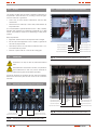
1
U N I N T E R R U P T I B L E P O W E R S U P P LY ( U P S ) + V O LTA G E S TA B I L I Z E R S A N D P O W E R L I N E C O N D I T I O N E R S + S W I TC H M O D E P O W E R S U P P LY + I N D U S T R I A L P O W E R S U P P LY servomotor voltage stabiliSers EMi2 series USER’S MANUAL + L I G H T I N G F LO W D I M M E R S TA B I L I Z E R S + S TAT I C I N V E R T E R S GENERAL INDEX 1.INTRODUCTION. 6. 1.1. 1.2. 1.2.1. 1.2.2. GRATEFULNESS LETTER. USING THIS MANUAL. Conventions and used symbols. For more information and/or help. 2. quality and standard guarantee. 2.1.management declaration. 2.2. standard. 2.3. environment. 6.1.maintenance basic guide. 6.2.troubleshooting and frequent asked questions (FAQ). 6.3.warranty conditions. 6.3.1. Covered product. 6.3.2. Warranty terms. 6.3.3. Out of scope of supply. 6.4.description of available maintenance contracts and services. 6.5.technical service network. 3. 7. Presentation. 3.1.front view. 3.1.1. Connectivity. 3.1.2. Synoptic. 3.2. DefiniTIOn and structure. 3.2.1. Nomenclature. 3.2.2. Structural diagram. 3.3. DescripTIOn OF THE SYSTEM. 3.3.1. Main quality performances. 3.3.2. Constructive features. 3.3.3. Operating principle. 3.4. Options. 3.4.1. Maximum-minimum output voltage protection. 3.4.2. Output ammeter Maintenance, warranty and service. Annexes. 7.1.particular technical specifications. 7.2. general technical specifications. 4.InstalLaTIOn. 4.1. Important safety instructions. 4.1.1. To keep in mind. 4.2. RecepTIOn of the equipment. 4.2.1. Unpacking and contents checking. 4.2.2. Transport. 4.2.3. Storage. 4.2.4. Location. 4.3. connection. 4.3.1. Connection terminals of single phase equipments. 4.3.2. Connection terminals of three phase equipments. 4.3.3. Connecting the earth. 4.3.4. Connecting the input. 4.3.5. Connecting the output. 4.4. start up and shutdown. 4.4.1. Start up. 4.4.2. Shutdown. 4.5. Bypass. 5. operaTING. 5.1. operating modes. 5.1.1. Regulator mode. 5.1.2. Bypass mode (Line). 5.1.3. Faulty operating modes. 5.2. important notes of its operating. SALICRU 3 1.INTRODUCTION. 1.1.GRATEFULNESS LETTER. We would like to thank you in advance for the trust you have placed in us by purchasing this product. Read this instruction manual carefully before starting up the equipment and keep it for any possible future consult that can arise. 1.2. The purpose of this manual is to give explanations and procedures for the installation and operating of the equipment. This manual has to be read carefully before installing and operating it. Keep this manual for future consults. 1.2.1. Conventions and used symbols. «Warning» symbol. Carefully read the indicated paragraph and take the stated prevention measures. We remain at you entire disposal for any further information or any query you should wish to make. USING THIS MANUAL. «Danger of electrical discharge» symbol. Pay special attention to it, both in the indication on the equipment and in the paragraph referred to this user’s manual. Yours sincerely. SALICRU The equipment here described can cause important physical damages due to wrong handling. This is why, the installation, maintenance and/or fixing of the here described equipment must be done by our staff or specifically authorised. According to our policy of constant evolution, we reserve the right to modify the specifications in part or in whole without forewarning. All reproduction or third party concession of this manual is prohibited without the previous written authorization of our firm. i «Main protective earthing terminal» symbol. Connect the earth cable coming from the installation to this terminal. i «Notes of information» symbol. Additional topics that complement the basic procedures. Preservation of the environment: The presence of this symbol in the product or in their associated documentation states that, when its useful life is expired, it will not be disposed together with the domestic residuals. In order to avoid possible damages to the environment, separate this product from other residuals and recycle it suitably. The users can contact with their provider or with the pertinent local authorities to be informed on how and where they can take the product to be recycled and/or disposed correctly. 1.2.2. For more information and/or help. For more information and/or help of the version of your specific unit, request it to our Service and Technical Support (S.T.S.). 4 USER MANUAL 2. quality and standard guarantee. 2.2. Standard. The EMi2 product is designed, manufactured and commercialized in accordance with the standard EN ISO 9001 of Quality Assurance. The marking shows the conformity to the EEC Directive by means of the application of the following standards: 2.1.management declaration. Our target is the client’s satisfaction, therefore this Management has decided to establish a Quality and Environmental policy, by means of installation a Quality and Environmental Management System that becomes us capable to comply the requirements demanded by the standard ISO 9001:2000 and ISO 14001:2004 and by our Clients and concerned parts too. Likewise, the enterprise Management is committed with the development and improvement of the Quality and Environmental Management System, through: • The communication to all the company about the importance of satisfaction both in the client’s requirements and in the legal and regulations • The Quality and Environmental Policy diffusion and the fixation of the Quality and Environment targets. • To carry out revisions by the Management. • To provide the needed resources. Management agent. EMC: • EN 61000-6-4: Standard generic emission. Industrial environment. • EN 61000-6-2: Standard generic immunity. Industrial environment. Safety: • IEC 60950-1: IT equipments. • IEC 61558-1: Safety of transformers, power supply, engines and similar products. 2.3. environment. This product has been designed to respect the environment and has been manufactured in accordance with the standard ISO 14001. Recycling the device at the end of its useful life: The Management has designated as management agent the person in charge about the Quality and Environment department, who with independence of other responsibilities, has the responsibility and authority to assure that the processes of the quality and environmental management system are established and maintained; to inform to the Management about the operating of the quality and environmental management system, including the necessities for the improvement; and to promote the knowledge of the client’s requirements and environmental requirements at all the levels of the organization. Our company commits to use the services of authorised societies and according to the regulations, in order to treat the recovered product at the end of its useful life (contact your distributor).. Packaging: To recycle the packing, follow the legal regulations in force. In the next PROCESS MAP is represented the interaction among all the processes of the Quality and Environmental System: continuous improvement process / management review quality management proces environmental management process R & D process technical office process CLIENTS: - PRODUCT - SERVICe CLIENTS COmMERCIAL process manufacturing process internal logistic process maintenance process training process Fig. 0. Process map of Quality and Environment system. SALICRU 5 3. PresentaTIOn. Stabilizer EMi2 has been designed for both to operate in unstable mains and to protect the critical loads. Input mains and output are marked in the terminals of the equipment. When doing the installation of this device, use the correct cross cable section in order to guarantee its correct operating. Switch 1-0-2 Control panels Stabilizer will automatically be shutdown when input voltage will be out of range, one phase will fault or any output will be shortcircuited. Once the failure has been solved the stabilizer will start up automatically again. In case of a failure shorter than the delay shutdown, the stabilizer will still be working. In case of a failure longer than the delay shutdown the stabilizer will automatically be shutdown. It has three LCD panels in the front side of the stabilizer, which are used to check the voltage applied to the input of the equipment. Input voltage can be checked with the indicators. Fig. 2. View of three phase 15kVA stabilizer EMi2 series The equipment shutdown and transference of input mains to the output is done through a switch type 1-0-2: 1: Bypass position from input to output. 0: Shutdown position. 2: Stabilizer position. Control panel 3.1.front VIEW. Switch type 1-0-2 Fig. 3. View of single phase 10kVA stabilizer EMi2 series 3.1.1. Connectivity. Control panels Switch type 1-0-2 Input phases R,S,T Fig. 1. Earth Neutral Output phases U,V,W View of three phase 60kVA stabilizer EMi2 series Fig. 4. Connection terminals of three phase model EMi2 T-60 6 USER MANUAL 3.1.2.2. LEDs Output Input Earth There are 7 LED indicators in the front panel: Neutral Input circuit breaker Fig. 5. View of rear side and connection terminals of single phase model 3.1.2. Synoptic. Indicator of output Indicators of output out of range LCD panel Indicators of displayed measurements Indicators of displayed measurement UP / DOWN buttons MODE button • Input voltage: This LED lights when the input voltage has been selected with button MODE. • Output voltage: This LED lights when the output voltage has been selected with button MODE. • Output current: This LED lights when the output current has been selected with button MODE. If the stabilizer doesn’t include this option of current transformers, when selecting this mode the LCD panel will display the value “0”. • Frequency: This LED lights when the output frequency has been selected with button MODE. • Output: This LED lights when there is voltage at the output. • High output: This LED lights when the output voltage is higher than the allowed limit. • Low voltage: This LED lights when the output voltage is lower than the allowed limit. 3.1.2.3. Buttons There are 3 buttons at the front side of the equipment. Their functions are: • Button MODE: It is used to monitor the input/output parameters. • Buttons : They are used to set the preset factory values and to make all calibrations. They do not have any use for the end user. 3.1.2.4. Dry contacts Fig. 6. View of indicators and buttons from synoptic The stabilizer has two relays that can provide the following information of “Output voltage out of range” and “Mains present / fault”. Synoptic is divided in 3 parts: • Display (seven segments). • LEDs • Buttons 3.1.2.1. Display (seven segments) If a contactor or relay is going to be used with the dry contacts of the stabilizer, a snubber has to be fitted at the output of the contactor or relay, which would be based on a resistor of 220Ω (2W) and capacitor of 470 nf (300V) both connected in serial. The relays are standard, but their outputs are only wired to its port/ terminal as an option. The following measurements can be monitored in the LCD panel: Input voltage, output voltage, output frequency and output current (as an option). These values are being displayed in the LCD panel when pressing button MODE. SALICRU 7 3.2. DefiniTIOn and structure. 3.2.1. Nomenclature. Three phase EMi2 series EMi2 T 20-2FBM-MR CO ±25% A 3x220V 60Hz ±4% “EE61153” Special equipment “EE” Output accuracy different from ±1% Frequency if it is not 50Hz Voltage, if it is not 3x400Vac A Digital output ammeter ±25% Input range, if it is different from ±15% CO “Made in Spain” silk screening in the equipment and packing (customs purposes) MR Max-min protection with automatic rearming M Max-min protection with manual rearming FBMIndependent phase regulation + manual bypass First character of voltage Power of the equipment in kVA Single phase EMi2 series EMi2 M 20-2BM-MR CO ±25% A 220V 60Hz ±4% “EE61153” Special equipment “EE” Output accuracy different from ±1% Frequency if it is not 50Hz Voltage, if it is not 230Vac A Digital output ammeter ±25% Input range, if it is different from ±15% CO “Made in Spain” silk screening in the equipment and packing (customs purposes) MR Max-min protection with automatic rearming M Max-min protection with manual rearming BM Manual bypass First character of voltage Power of the equipment in kVA 3.2.2. Structural diagram. Max.-min. protetions (*) Bypass manual SALIDA INPUT EMI2 Stabilizer Input switch (*) Opcional Fig. 7. 8 Single line diagram of EMi2 stabilizer USER MANUAL 3.3. Description of the system. Voltage stabilizer from EMI2 series is a voltage regulator that, due to its simplicity, reliability and robustness, has achieved to persist along the ages, but with a complete redesigning which has included technical improvements, both electrical and mechanical. It is very useful in those applications, without requiring a fast response time but requiring a constant and accurate stabilization. Voltage stabilizer provides protection against sudden changes, irregularities, increasing and decreasing of mains voltage by means of an accurate voltage stabilization. Also, an optional module provides protection against maximum and minimum output voltages, protecting the loads by disconnecting the output through a contactor when the voltage exceeds the allowed range or any phase is missed. There is a delay of 2 seconds between the turning on/ off the contactor, in order to keep the protection against sudden fluctuations in mains. Also, it has a manual Bypass. Stabilizer can be used to stabilize the voltage of any type of computer, fax, photocopier, medical equipment, home or office lighting, power supply for apartment or office buildings, tools machines, etc. Stabilizer makes a sensitive, fast and efficient stabilization of the output voltage through the incorporated Booster transformer, variac and microprocessor. 3.3.2. Constructive features. Equipment is built from three single phase stabilizers with independent control per each phase. This way, each phase is regulated, as regards to neutral, to the nominal voltage, without modifying the voltage of the other ones, whatever the load percentage is connected to each phase. Each phase is protected with its own circuit breaker, which avoids, against direct short-circuits to trip the general protection. Equipment has indicators made of light emitting diodes in its frontal part, which inform us about the status of the equipment. 3.3.3.Operating principle. The electronic control supervises the output voltage of the stabilizer continuously, providing a correction signal to the step by step motor, in case the sensed voltage is wrong. Motor moves the autotransformer ARC, in order to increase or decrease the voltage, by moving the carbon brush to left or right. The resulting voltage is applied to the primary winding of ‘Booster’ transformer which adds in phase or counter phase to mains voltage through its secondary winding, this way any fluctuation on mains voltage is corrected. To keep the output stable inside a minimum tolerance, the servo system uses a control through thyristors to manage the DC motor. LCD panel can display the following values input/output voltages, frequency and current (as an option). Also, LED indicators of synoptic provide information about the status of the equipment: output voltage present / fault, high / low. It is also possible to receive information through dry contact interface. Fuses at front panel provide protection for loads and stabilizer against overcurrents. Forced cooling is used in those models higher than 30kVA, either single phase or three phase, in order to keep a stable internal temperature. Below this power the cooling is natural. Under request, it is possible to manufacture the models with wide input voltage range of ±25% (input regulation window). 3.3.1. Main quality performances. Among others, the main quality performances of this series are: • High efficiency. • Electromechanical protection of maximum-minimum voltage (optional). • Short-circuit protection. • Operating with non-linear loads. • Wide input voltage range (optional). • Warranty for 10 years (optional). SALICRU 9 3.4.OpTionals. 3.4.1. Maximum-minimum output voltage protection. Basically, it is detector of maximum and minimum voltage, which is located at the output of any stabilizer or conditioner, either single phase or three phase and it analyses, at all times, the output voltage of the own equipment. If the output voltage is inside the range ±7,5 % of nominal, the equipment supplies voltage and feeds the loads connected to the device. In case the output voltage is out from this range, the detector breaks the electrical power supply to the loads to feed. There are two different standardised versions of protection: 3.4.1.1. Manual version (M), start up. Manual rearming. As maximum-minimum voltage protections are located between the stabilizer and output terminals, although the led «Output» is turned on and the output voltmeter displays the voltage value, it doesn’t mean that there is voltage in the output terminals. Proceed to start up the stabilizer, the equipment will supply voltage at its output. The device is ready, start up the loads to be fed. 3.4.1.2. Automatic version (MR), start up. Automatic rearming. As maximum-minimum voltage protections are located between the stabilizer and output terminals, although the led «Output» is turned on and the output voltmeter displays the voltage value, it doesn’t mean that there is voltage in the output terminals. Proceed to start up the stabilizer, if output voltage is inside the range ±7,5 % the equipment will supply output voltage. The device is ready, start up the loads to be fed. This version, if the output voltage is out of the quoted range, the equipment will disconnect the system automatically, till the voltage is restored to its nominal value of ±7,5 %. The re-connection of the equipment is delayed 15 seconds approximately, in order to avoid unnecessary connections and disconnections. 3.4.2. Output ammeter Under request, it is possible to provide the LCD panel with the output current measurements per phase. 10 USER MANUAL 4.INSTALLATION. 4.1.1.To keep in mind. Stabilizers are used to protect the critical loads against mains fluctuations, this way it makes possible an optimal operating of them. 4.1.Important safety instructions. For safety of user, data and product read carefully the following instructions before installing the equipment! • System has been designed to provide all safety conditions to protect the electronic equipments of the office, including the IT systems. In case there was any question, call to technical service (S.T.S.) • To avoid damages to the equipment, transport it inside its own packaging. • In case of sudden changes in temperature, from cold to normal operating temperature, it is possible to form condensations inside the device. It is absolutely essential to start up the equipment when it is completely dry. Therefore, wait for two hours as minimum, before operate with it. • Once dry, check that all environmental conditions of the equipment stated in the technical specifications are met before making the connection. • Once the equipment is installed, use the suitable cross cable section to make the connection. Neutral and earth has to be properly connected. • Arrange the wiring in such way, that it does not exist any risk of electrocution or it does not obstruct the way and cause an accident. Before starting up, read carefully all instructions and warnings in the chapter dedicated to its location and operating. • Avoid that strange objects (clips, bolts, etc.) enter inside the equipment. • In emergency situations (damages in both front panel and in input connections or strange objects or liquids inside the equipment), shutdown the equipment immediately, disconnect it from mains and call to technical service (S.T.S.). • Stabilizer can only be repaired by an authorised engineer from technical staff (S.T.S.). To open the equipment or any repairing attempt by any non-authorised person will be very dangerous and will invalidate the warranty. • Do not connect any load to the stabilizer that exceed its power capacity. • Read the maintenance and clean section carefully when the equipment is going to be cleaned. • Always leave 30cm. between the equipment and walls in order to guarantee that cooling is enough. Those points about safety have been detailed in section 4.1. Important safety instructions. Now, these points will be repeated in order to provide information about the connections of both stabilizer and loads. • When installing the stabilizer, the use of inappropriate cross cable sections can entail danger for the user and for the integrity of the device. • Earth cable has to be sized according to its current capacity, which is shown in the front nameplate of the stabilizer. All earth connections have to be done with this cable. To not earth the equipment, or to make an inappropriate connection, the equipments will mean a danger for the user and high risk of faults in the electronic circuit. 4.2.equipment reception. 4.2.1. Unpacking and content checking. • Before unpacking, check that the stabilizer has not been damaged during transport. i If there were any damage in the packaging, contact with the transport agency. Check that all parts have been supplied with the equipment. Contents: Automatic voltage stabilizer. User’s manual CD. By means of forklift trucks move the unit to the suitable location to make its installation. 4.2.2. Transport. Stabilizer has to remain in vertical position during transport. Check that the floor can support the weight of the equipment. In case the equipment has to be transported again, make sure that it is packaged properly, therefore it is recommended to preserve the original packaging. 4.2.3. Storage. Equipment can be stored in a dry location between -25ºC and +55ºC. Relative environment humidity has to be between 20% and 95%, non-condensing. SALICRU 11 4.3.2. Connection terminals for three phase equipments. 4.2.4. Location. This product complies with the safety standards for equipments to be operated in restricted areas. So, according to the local regulations the owner has to guarantee: • Access only for both technical maintenance staff and duly trained users. • Restricted access under key or other safety measurements by responsible staff. It is recommended to operate between 0ºC and +40ºC, humidity between 20% and 95% non-condensing and altitude up to 1000 metres. It is possible to require an air-conditioning to comply these premise. Other requirements: • Equipment should not have to be exposed to direct sunlight. • Do not expose the equipment to rain or liquids, in general. Do not enter any object inside. • Avoid dusty locations or areas where conductive dust or corrosive materials are present. • Preserve a space of 20 cm. in front of the cooling grids. 4.3. connection. Earth terminal PE) Input terminal phase R Output terminal phase W Input terminal phase S Output terminal phase V Input terminal phase T Output terminal phase U Input terminal neutral N Output terminal neutral N Fig. 9. Connection terminals for 15kVA three phase model Connections can only be done by authorised technical staff. If the stabilizer is moved from its location, it is possible to have condensation. In that case, wait as minimum for two hours before starting with the installation procedure. Connection terminals are located in the front side of the stabilizer. Remove the lower front panel to have access to the connection terminals. 4.3.1. Connection terminals for single phase equipments. Input terminal phase R Input terminal phase S Input terminal phase T Input terminal neutral N Input terminal phase R Input terminal neutral N Earth terminal (PE) Output terminal phase R Output terminal neutral N Earth terminal (PE) Output terminal phase W Output terminal phase V Output terminal phase U Output terminal neutral N Fig. 10. Connection terminals for 60kVA three phase model Fig. 8. Connection terminals for 10kVA single phase model 12 USER MANUAL 4.3.3. Connecting the earth Both for safety and an operation without faults, the equipment has to be earthed. Earth the equipment before doing any connection. Earthing terminal has to be connected to an electrical mains of good quality (low impedance). Load earthing connection should be done through the earth bonding terminal at the output of the stabilizer. Before doing the connections, all inputs, output fuses from stabilizer and circuit breakers from switchgear panel have to be in position “0”. Loads are connected to OUTPUT, NEUTRAL and EARTH terminals of the stabilizer. Cross cable section between the stabilizer and loads has to be sized properly and according to the current drawn by the loads. Maximum power of the connected loads does not have to exceed the nominal power of the stabilizer. 4.3.4. Connecting the input. A circuit breaker of two poles and an earth leakage breaker has to be added in the electrical line, phase-neutral, of the switchgear panel that supplies the stabilizer. It is recommended the use a circuit breaker in the switchgear panel with the same size of the circuit breaker of the stabilizer. Circuit breaker size and type are defined in the technical specifications. Earth leakage breaker should be sized with the sum of the earth leakage currents of the loads plus 30mA more. These figures of current have been defined considering that the stabilizer is only supplied from the circuit breaker of the switchgear panel. Otherwise, they should again be calculated considering all loads. Any variation in the switchgear panel has to be done by technical staff. Once all changes have been finished, move the circuit breaker switch to position “0”. Connect the lines (phases) and neutral to their corresponding terminals through the circuit breaker. Before connecting the input cables, the circuit breaker of the switchgear panel has to be in position “0”. Minimum cross cable section between the stabilizer and switchgear panel has to be according to the power rate of the stabilizer. In case of sizing a lower cross cable section, could be risk of fire. 4.3.5. Connecting the output. 4.4. START UP AND SHUTDOWN. 4.4.1. Start up. Once the connection of the equipment has been done, to start up the equipment, it is enough by turning to position “I” all circuit breakers of switchgear panel and to turn to position “Regulation” all fuses of the stabilizer. If input mains is inside the allowed voltage range, the stabilizer will be started up. 4.4.2. Shutdown. To shutdown the equipment, turn all fuses and circuit breakers from stabilizer and switchgear panel to position “0”. In case of maintenance tasks in the stabilizer without disconnecting the loads, move the Bypass switch to position “Line”. 4.5.Bypass. Manoeuvring switch type 1-0-2 can be turned to position (1) or Bypass, which makes a direct connection of the equipment output with its input. This operating can be used, when in case of equipment failure, the loads can’t be shutdown. It is recommended the use of separate circuit breakers and earth leakage breakers at the output of the stabilizer, in case it feeds several loads. If each load is connected to the stabilizer through separate circuit breakers, in case of a short-circuit in any load, the circuit breaker of the short-circuited line will trip, and the rest of connected loads will not be affected. The size of the circuit breakers of the loads has to be lower than the value of the short-circuit current. Otherwise, in case of shortcircuit, circuit breaker will not trip in less than 10ms and all loads will be shutdown. SALICRU 13 5. operaTING. 5.1. operating modes. 5.1.1. Regulator mode. The equipment operates on regulator mode when input voltage is inside the specified range. In this mode, the equipment stabilizes the input voltage and feeds the loads at the nominal input voltage with its particular tolerance range. Input range values and output accuracy are described in the technical specification section. 5.1.2. Bypass mode (Line). Loads can be transferred to Bypass mode by means of turning the switch to position LINE. Loads are directly supplied from mains in this mode. Bypass mode is usually used to make the maintenance of the stabilizer. 5.1.3. Faulty operating modes. 5.1.3.1. Overload. 5.2. important NOTES OF ITS OPERATING. Stabilizer is used to protect those equipments sensitive to damages due to a bad quality or fluctuations of the electrical mains. The enduser, from the quality supplied by mains, is ready, to supply clean and good quality energy to their equipments by means of using the stabilizer. Inside a building, the electrical distribution system should be made in a professional way and according to the distribution and earth principles, by using duly cables with quality and cross section. The end-user has to pay attention to important aspects when installing the stabilizer between the load and mains. The following points are important for his safety and correct operating of the equipment: • Connection of the stabilizer to mains has to be done by authorised staff and according to both the instructions stated in the installation section and by using the proper cross cable section. • Stabilizers have to be fed through a switchgear panel with main earthing connection and protected with a suitable sized fused for the stabilizer according to the label located in its rear side. • Risk of electrocution exists for the user when it is used a switchgear panel with an inadequate main earthing connection or without it to feed the stabilizer. Also, the possibility of faults in the electronic circuits is increased. • Distribution system of some buildings has outlets with phase and neutral only that, they seem that are connected to earth properly, but they aren’t. In those cases, the earth has been connected to the neutral or it has not been connected. When these outlets or others in parallel with them are connected to the critical loads, the voltage in the neutral will be different from the earth one, causing a risk of electrocution. Also, all the equipments connected to them will have a higher risk of failures. When the stabilizer is loaded exceeding its nominal power capacity, there is an overload. When the equipment is overloaded in regulator mode, it still supplies the load till the output fuse is blown. For safety operating, do not overload the stabilizer. 5.1.3.2. Output short-circuit. In case of short-circuit, the stabilizer is a current source and tries to blown the fuse of the short-circuited line. When doing it, the shortcircuit situation is cancelled and the rest of loads are not affected for this condition. Stabilizer can only make the described short-circuit behaviour, if the loads connected to the stabilizer are protected by separate / independent fuse protections and if they are sized according their load nominal currents. 14 USER MANUAL 6. Maintenance, warranty and service. 6.1. basic maintenance guide. • It is not needed any maintenance by the user side. From time to time dust the fans. Check that the input BYPASS and OFF fuses are in position “0” before cleaning. • Do not use detergent or cleaning materials that could damage the plastic parts. • Do not enter any liquid inside the device. • Check that the cooling grids are cleared. • The stabilizer body can be cleaned with a dry and clean cloth. 6.2.TROUBLESHOOTING and frequent asked questions(FAQ). In case of faults or wrong operating of the stabilizer, before calling the technical service, check the following points (S.T.S.): • Is the switchgear panel connected to mains? • Are the Input fuses/ circuit breakers blown / tripped? Bring the following data to the authorised technical service (S.T.S.): • Details of the equipment stated in its nameplate (model, serial number). • Description of the fault. 6.3.WARRANTY CONDITIONS. The limited warranty by SALICRU, S.A. only applies to those products that you acquire for commercial or industrial use in the normal development of your business. 6.3.1. Covered product. Voltage stabilizer from EMi2 series. 6.3.2.Warranty terms. SALICRU, S.A. guarantees the product against any parts and/ or labour defect for 12 months period from its commissioning by SALICRU, S.A. staff or other specifically authorised, or 18 months from its factory delivery, whichever expires first. In case of failure of the product inside the warranty period, SALICRU, S.A. must repair, at your facilities at no cost, the faulty part or parts. The transport expenses and packaging will be borne to the user. SALICRU For equipments out from the national territory, contact with the Export Department. SALICRU, S.A. guarantees for period time higher than 10 years, the availability of parts and spare parts, as hardware as software, as well as a complete assistance regarding the reparations, components replacement and software updating. 6.3.3.Out of scope of supply. SALICRU, S.A. is not forced by the warranty if it appreciates that the defect in the product doesn’t exist or it was caused by a wrong use, negligence, installation and/or inadequate testing, tentative of repairing or not authorized modification, or any other cause beyond the foreseen use, or by accident, fire, lightnings or other dangers. Neither it will cover, in any case, compensations for damages or injuries. 6.4.available maintenance and service contracts. When the warranty is expired, SALICRU, S.A., adapting to the customer’s needs, has several maintenance modalities: • Preventive. It guarantees a higher safety to preserve the correct operating of the equipments with a yearly Preventive visit, in which the specialised technicians from SALICRU, S.A. make several tests and sets in the systems: Check and write down the input and output voltages and currents per phase. Check the logged alarms. Check the readings of the LCD panel. Other measurements. Check the fan status. Check the load level. Check the selected language. Check the correct location of the equipment. General cleaning of the equipment. This way, it is guaranteed the perfect operating and the possible coming faults are avoided. These supervisions are usually done without shutdown the equipment. In those cases that a shutdown were needed, date and time would agree with the customer to do the task. This maintenance modality covers, inside the working timetable, all the journey expenses and manpower. • Corrective. When a fault occurs in the equipment operating, and previous notice to our Service and Technical Support (S.T.S.), in which a specialized technician will establish the failure scope and he will determine a first diagnostic, the corrective action starts. The needed visits for its correct resolution are unlimited and they are included inside the maintenance modalities. It means that in case of failure, SALICRU, S.A. will check the equipments as many time as it were needed. 15 Besides, inside these two modalities, is possible to fix the action timetable and response times in order to be adapted to the customer’s needs: LV8HLS. Customer’s attention from Monday to Friday from 9 h. to 18 h. The response time is inside the same day or, as maximum, in the next 24 hours of the fault notification. LS14HLS. Customer’s attention from Monday to Saturday from 6 h. to 20 h. Response time is inside the same day or, as maximum, at first time of the next working day. LD24HLS. Customer’s attention from Monday to Sunday 24 h., 365 days per year. Response time in less than two or three hours after the fault notification. • Additional arrangement: 1-m-cb. • Index 1. It means the number or Preventive visits per year. It includes displacement and manpower expenses inside the established timetable for each maintenance modality, as well as all the needed Corrective visits. Excluding all the parts and batteries in case of reparation. 6.5. technical service network. The covering, as national as international, of Service and Technical Support (S.T.S.) points, are made up by: At national level: Andorra, Barcelona, Madrid, Bilbao, Gijon, A Coruña, Las Palmas de G. Canaria, Málaga, Murcia, Palma de Mallorca, San Sebastian, Santa Cruz de Tenerife, Seville, Taco (La Laguna - Tenerife), Valencia and Zaragoza. At international level: France, Brazil, Hungary, Portugal, Singapore, U.K., China, Mexico, Uruguay, Chile, Venezuela, Colombia, Argentina, Poland, The Philippines, Malaysia, Pakistan, Morocco, Thailand, Emirates Arabs United, Egypt, Australia and New Zealand. Index m. It means to include all the spare parts. Index cb. It means to include batteries. 16 USER MANUAL 7. AnNexEs. 7.2. general technical specifications. Input 7.1. Voltage PARTICULAR TECHNICAL SPECIFICATIONS. Input range (1) Single phase models EMi2 M 5-2BM Regulation range (%) Voltage (V) and accuracy Max. output Efficiency (%) Single phase 230 V, Three phase 3x400 V Normal (standard) 195 - 265 Vac (230Vac ±15%) Wide (option) 172 - 288 Vac (230Vac ±25%) Frequency 48 ÷ 63 Hz Nominal current See section 7.1. depending on the model Output 5 ±15% 230±1% 21,7 ≥ 96 Voltage EMi2 M 7,5-2BM 7,5 ±15% 230±1% 32,6 ≥ 96 Accuracy(2) EMi2 M 10-2BM 10 ±15% 230±1% 43,5 ≥ 96 Disconnection voltage value EMi2 M 15-2BM 15 ±15% 230±1% 65,2 ≥ 96 Frequency EMi2 M 20-2BM 20 ±15% 230±1% 87 ≥ 96 Nominal power See section 7.1. depending on the model EMi2 M 25-2BM 25 ±15% 230±1% 108,7 ≥ 96 Maximum current See section 7.1. depending on the model EMi2 M 30-2BM 30 ±15% 230±1% 130,4 ≥ 96 Tabla 1. Particular technical specifications for single phase models. Response time Single phase 230 V, Three phase 3x400 V ±1% 200 - 240 Vac (3) 48 ÷ 63 Hz 2 - 15kVA single / 6 - 45kVA three 80 V/s > 15kVA single / > 45kVA three 40 V/s Efficiency Three phase Regulation rage (%) Voltage (V) and accuracy Max. output Efficiency (%) See section 7.1. depending on the model Power factor 1 Crest factor 3 to 1 Harmonic distortion Nil EMi2 T 15-4FBM 15 -±15% 400±1% 21,7 ≥ 96 EMi2 T 20-4FBM 20 ±15% 400±1% 29 ≥ 96 EMi2 T 30-4FBM 30 ±15% 400±1% 43,5 ≥ 97 EMi2 T 45-4FBM 45 ±15% 400±1% 65,2 ≥ 97 EMi2 T 60-4FBM 60 ±15% 400±1% 87 ≥ 97 EMi2 T 75-4FBM 75 ±15% 400±1% 108,7 ≥ 97 EMi2 T 90-4FBM 90 ±15% 400±1% 130,4 ≥ 97 EMi2 T 110-4FBM 110 ±15% 400±1% 159,4 ≥ 97 EMi2 T 140-4FBM 140 ±15% 400±1% 202,9 ≥ 95 EMi2 T 160-4FBM 140 ±15% 400±1% 231,2 ≥ 97 Operating temperature -5 to +55ºC EMi2 T 220-4FBM 220 ±15% 400±1% 319 ≥ 97 Storage temperature -30 to +70ºC EMi2 T 275-4FBM 275 ±15% 400±1% 398,5 ≥ 97 Relative humidity EMi2 T 330-4FBM 330 ±15% 400±1% 478 ≥ 97 Mean Time Between Failures (MTBF) 60.000 hours Mean Time To Repair (MTTR) 30 minutes Tabla 2. Particular technical specificatgions for three phase models. Generals input/output voltage, output Intensidad (optional), output frequency (digital) Front panel Indicators: Stabilizer in operating, High / Low output voltage Output present / stabilizer ON (NO, C, NC) Dry contacts Warning for high / low output voltage (NO, C, NC) Noise level at 1 metre ≤ 45 dB (A) 0 to 95%, non-condensing STANDARDS Electromagnetic Compatibility (EMC) Safety EN 61000-6-4; EN 61000-6-2 IEC 60950-1; IEC 61558-1 Tabla 3. General specifications of all EMi2 series. (1) When input voltage exceeds the allowed values, the stabilizer checks its output and disconnects in those versions “with circuit breaker”. In case the circuit breaker module is not present, the stabilizer continues supplying output according to its transformation ratio. Once the input voltage returns to the allowed limits, the stabilizer starts up in normal operating automatically. (2) Output voltage accuracy can be set to other value under request. (3) This value can be set to other value under request. SALICRU 17 NOTES: . ............................................................................................................................................................................................... .............................................................................................................................................................................................................. .............................................................................................................................................................................................................. .............................................................................................................................................................................................................. .............................................................................................................................................................................................................. .............................................................................................................................................................................................................. .............................................................................................................................................................................................................. .............................................................................................................................................................................................................. .............................................................................................................................................................................................................. .............................................................................................................................................................................................................. .............................................................................................................................................................................................................. .............................................................................................................................................................................................................. .............................................................................................................................................................................................................. .............................................................................................................................................................................................................. .............................................................................................................................................................................................................. .............................................................................................................................................................................................................. .............................................................................................................................................................................................................. .............................................................................................................................................................................................................. .............................................................................................................................................................................................................. .............................................................................................................................................................................................................. .............................................................................................................................................................................................................. .............................................................................................................................................................................................................. .............................................................................................................................................................................................................. .............................................................................................................................................................................................................. .............................................................................................................................................................................................................. .............................................................................................................................................................................................................. .............................................................................................................................................................................................................. .............................................................................................................................................................................................................. .............................................................................................................................................................................................................. .............................................................................................................................................................................................................. .............................................................................................................................................................................................................. .............................................................................................................................................................................................................. .............................................................................................................................................................................................................. .............................................................................................................................................................................................................. .............................................................................................................................................................................................................. .............................................................................................................................................................................................................. .............................................................................................................................................................................................................. .............................................................................................................................................................................................................. .............................................................................................................................................................................................................. 18 USER MANUAL + V O LTA G E S TA B I L I Z E R S A N D P O W E R L I N E C O N D I T I O N E R S + S W I TC H M O D E P O W E R S U P P LY + I N D U S T R I A L P O W E R S U P P LY + L I G H T I N G F LO W D I M M E R S TA B I L I Z E R S + S TAT I C I N V E R T E R S Avda. de la Serra, 100 08460 Palautordera BARCELONA Tel. +34 93 848 24 00 902 48 24 00 Fax. +34 94 848 11 51 [email protected] Tel. (S.T.S.) 902 48 24 01 Fax. (S.T.S.) +34 848 22 05 [email protected] SALICRU.COM BRANCHES AND SERVICES and TECHNICAL SUPPORT (S.T.S.....) MADRID PALMA DE MALLORCA BARCELONA PAMPLONA BADAJOZ SAN SEBASTIAN BILBAO SANTA CRUZ DE TENERIFE GIJÓN SEVILLA LA CORUÑA VALENCIA LAS PALMAS DE G. CANARIA VALLADOLID MÁLAGA ZARAGOZA MURCIA SUBSIDIARIES FRANCIA RUSIA PORTUGAL CHINA HUNGRIA SINGAPUR REINO UNIDO MÉXICO POLONIA URUGUAY REST of WORLD ALEMANIA ECUADOR BÉLGICA PERÚ DINAMARCA ARABIA SAUDÍ GRECIA ARGELIA HOLANDA EGIPTO IRLANDA JORDANIA NORUEGA KUWAIT REPÚBLICA CHECA MARRUECOS SUECIA TÚNEZ SUIZA KAZAJSTÁN UCRANIA PAKISTÁN ARGENTINA FILIPINAS BRASIL INDONESIA CHILE MALASIA COLOMBIA TAILANDIA Product Range Uninterruptible Power Supply UPS Voltage Stabilizers and Power Line Conditioners Switch Mode Power Supplies Industrial Power Supplies Lighting Flow Dimmer-Stabilizers Static Inverters Continuous Regulation Autotransformers EK839A01 Nota: Salicru can give other electronics solutions according to the application specifications or technical specifications. U N I N T E R R U P T I B L E P O W E R S U P P LY ( U P S )