1
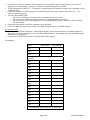
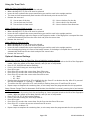
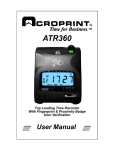
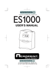
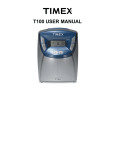
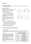
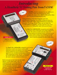
Model ATR360 Quick Start Setup
For complete instructions please reference the ATR360 User Manual,
website: www.acroprint.com or call Service at 919-872-5800 Option 1.
Initial Setup:
Remove top cover by turning clock key and pulling up, locate buttons at the top of the clock labeled P4, P5
and P6 and program switch to the left of the fingerprint reader. Move the switch to the down position, now
you are in setup mode.
• P4 changes values down
• P5 changes values up
• P6 is used to save and select modes
Setting Year
• The mode indicator “01” will be flashing, press P6 to select
• Press P4 or P5 to select the current year and Press P6 to Save
Setting Month/Date
• The mode indicator “02” will be flashing, press P6 to select
• Press P4 or P5 to select the current month and Press P6 to Save
• Press P4 or P5 to select the current date and Press P6 to Save
Setting Time
• The mode indicator “03” will be flashing, press P6 to select
• Press P4 or P5 to select the current hour and Press P6 to Save
• Press P4 or P5 to select the current minute and Press P6 to Save
Setting Day Advance Time
• The mode indicator “04” will be flashing, press P6 to select
• Press P4 or P5 to select the current hour and Press P6 to Save
• Press P4 or P5 to select the current minute and Press P6 to Save
Setting Card Format
• The mode indicator “05” will be flashing, press P6 to select the format by pressing P4 or P5
o Set 00 for first row blank - for weekly and bi-weekly pay periods
o Set 01 prints on first row – for monthly and bi-monthly pay periods
• Press P6 to save
Setting Pay Period
• The mode indicator “06” will be flashing, press P6 to select the pay period type by pressing P4 or P5
o If the pay period is monthly or bi-monthly select 00
o If the pay period is weekly or bi-weekly select 01
• Press P6 to save
Setting Clock Display Format
• The mode indicator “07” will be flashing, Press P6 to select
• Press P4 or P5 to select the clock display format (12-hour or 24-hour/military)
• Press P6 to save
Setting Printing Position
• The mode indicator “08” will be flashing, Press P6 to select (NOTE: OK to skip this step unless the printed
registration is not positioned well in the box.)
• Press P4 or P5 to select
o Set 00-15 for vertical axis
o Set 00-30 for horizontal axis
• Press P6 to save
Page 1 of 6 06‐0421‐000 Rev. B
Setting Start and End of DST
• Set the Start Date of DST:
o The mode indicator “09” will be flashing, press P6 to select
o Press P4 or P5 to select the correct month (US-March) and Press P6 to save
o Press P4 or P5 to select the correct date and Press P6 to save (2nd Sunday)
o Press P4 or p5 TO select the correct start time (US-2am) and Press P6 to save
• Set the End Date of DST:
o The mode indicator “09” will be flashing, press P6 to select
o Press P4 or P5 to select the correct month (US-Nov) and Press P6 to save (1st Sunday)
o Press P4 or P5 to select the correct date and Press P6 to save
o Press P4 or p5 TO select the correct start time (US-2am) and Press P6 to save
Setting Print Format (different from Setting Clock Display Format
• The mode indicator “10” will be flashing, press P6 to select
• Press P4 or P5 to select the correct print format and Press P6 to save
o 00 – 24 hour (Military Time)
o 01 – Decimal Hours (0-99 hundredths rather than 0-59 minutes)
o 01 – 12 hours (pm)
Setting Time Card Recognition
• The mode indicator “11” will be Flashing, press P6 to select
• Press P4 or P5 to select the correct the correct time card format and Press P6 to save
o 00 – Monthly, Semi-Monthly
o 01 – Weekly, Bi-Weekly
Initial setup is complete. Locate the program switch to the left of the fingerprint reader, move it to the up
position and replace top cover. You can begin using the time clock. If you want to use set Fingerprint or Badge
settings, please continue with setup.
Introduction on Fingerprint (FP) and Badge Setup
•
•
•
•
•
•
Remove top cover by turning clock key and pulling up, locate program switch to the left of the fingerprint
reader. Move the switch to the down position, now you are in setup mode.
o The FP is OFF when the fingerprint reader is dim
o The FP is on when the fingerprint reader will emits a glow
During this set up process, if no activity is detected within 30 seconds, the setup program will be
terminated. To enter back into the setup process, the “FP” setup button must be pressed again.
Time clock can hold 150 fingerprint templates (with 1 assigned fingerprint), or 75 employees (with 2
assigned fingerprints), or 50 employees (with 3 assigned fingerprints), etc.
Time clock can have 5 administrators, who can punch anytime, and can have up to three fingerprints
When you setup an employee or administrator you are given a number (i.e. U001 or A301); please write
this information down and keep in safe place for future setup questions. (Note: The Administrator can
punch anytime on any card. This allows them to “punch in or out” for an employee who wants to “punch in
or out” outside his assigned shift.)
User can use either fingerprint or badge; instructions for both are below:
Fingerprint Setup
For employees
• Press the “FP Setup” button located at the left of the fingerprint reader stop when ADD.U appears in the
bottom LED display. When ADD.U appears on the display press the enter button one time until U001
appears (U001 is the default for the first user, range of numbers is U001-150).
• This is where we register the fingerprints for each user.
o FP1.1 will appear on the display press enter button 1 time until the “1” to the right is blinking put
the first finger onto the reader
o If it reads properly FP1.”2” will blink, put the same finger onto the reader for a second reading
o If it reads properly FP1.”3” will blink, put the same finger onto the reader for last reading.
• Once the 3rd fingerprint sample has been properly entered PASS will appear on the display and a small
green light will appear below OK to confirm
Page 2 of 6 06‐0421‐000 Rev. B
•
•
•
•
•
•
If you do not require a second or third fingerprint to be registered, press cancel and the next user will
appear in the small display. To register a second and third fingerprint, see below.
The LED display will read F.P.2.1 – to register a second fingerprint follow the above steps, remember to use
a different finger
If you desire to enter a third fingerprint continue with the same steps using the selection F.P.3.1 – to
register a third fingerprint.
To create the number U002:
o 001 first 0 is blinking to change press up or down button press enter
o 001 second 0 is blinking to change press the up or down button press enter
o 001 last number will be blinking press the up or down button to get 2 then press enter and hold
for two seconds
Follow the steps above until all the employees are registered.
To exit the ADD.U program press Cancel until ADD.U appears on the small LED display.
For administrators
• To enter Administrative fingerprint: when ADD.U appears, press the enter button until U001 appears on
the screen. Press the up button 2 times and A301 should appear. Then follow the same procedure to add
administrator’s fingerprint.
• Continue on to Real Time Clock (RTC) and Duration (DUR) settings
See diagram:
Admin Emp. Name Emp. Number A101 A102 A103 Employee U001 U002 U003 U004 U005 U006 U007 U008 U009 U010 U011 U012 U013 U014 U015 Use separate sheet for more than 15 employees Page 3 of 6 06‐0421‐000 Rev. B
Badge (Card) Setup
•
•
•
•
•
•
•
The user may also be issued a badge in place of using the fingerprint reader, set up follows the same
procedure as entering a fingerprint (see above)
When ADD.U appears on the display press the enter button one time U001 will appear the first time - this
is where you will enter the user number (001-150)
o 001 first 0 is blinking to change press up or down button press enter
o 001 second 0 is blinking to change press the up or down button press enter
o 001 last number will be blinking press the up or down button to get 2 then press enter and hold
for two seconds
FP 1.1 will appear on the display and flash, press the up or down button until RFid appears on the display
With RFid on the display Press enter the LED display will read “CARD”
Scan the card. If the card is successfully scanned the LED display will indicate “PASS”
Press the CANCEL button to return to the ADD.U screen
Continue on to Real Time Clock (RTC) and Duration (DUR) settings
Real Time Clock (RTC)
RTC synchronizes the Fingerprint and Badge clock with the digital clock
• Press the UP or DOWN button to locate RTC. Once RTC appears on the screen hold the enter button down
for approximately 3 seconds
o 2 sets of digits will flash, the 1st set of digits is the hour, set this to your current hour as it reads
on the main display and then press enter
o 2nd set of digits are now flashing, change the minutes to 2 minutes ahead of your time on the main
display, press and hold the enter button down for approx 3 seconds, PASS should appear
• Once the hour and minute are saved a set of 2 numbers will appear on the display, these are the seconds,
enter 00 and wait for the time to change on the main display, hold the enter button down for 3 seconds,
PASS will once again appear on the display, this will confirm that the display and fingerprint reader are
synced together for a more accurate reading.
Duration (DUR)
This setting is the amount of time in seconds the employee has to insert their time card once the fingerprint
or badge has been activated, if you fail to insert the time card during the time allotted, the punch will be
treated as a duplicate punch and no print will be registered. Note: The default duration setting is for 3
seconds. We recommend duration of 5 to 10 seconds.
• Press the UP or DOWN button to locate DUR.
• To change the setting once DUR appears on the display press the enter button use the up and down button
to adjust the time in seconds, press and hold the Enter button down for 3 seconds if PASS does not appear
use a small number.
In Out Shift Intervals for both the Fingerprint and Badge (InO.S): Shift Intervals prevent the
employee from punching more than once during a shift interval, to prevent Buddy punching; you may have up
to 12 schedules/Intervals. During each interval employees may only use the fingerprint (badge) one time
unless they are set up as Administrator.
The 4 default intervals are listed below:
PE1
07:00 to 11:00
PE2
11:01 to 13.20
PE3
13:21 to 16:30
PE4
16:31 to 20:00
PE5 thru PE12 are available but are empty.
Before you begin to adjust In Out shift Intervals – write down all the shift intervals required by your company
and store them in a safe place.
Page 4 of 6 06‐0421‐000 Rev. B
See diagram:
In Out Shift Intervals Company Date Example From PE1 7:00
PE2 11:01
PE3 13:21
PE4 16:31
Actual From PE1 PE2 PE3 PE4 PE5 PE6 PE7 PE8 PE9 PE10 PE11 PE12 To 11:00
13:20
16:30
20:00
To To adjust InO.S.
• Go to InO.S. on the display and press the enter button 1 time PE1 will appear –Press Enter, this is the start
time for interval number 1 use the up and down buttons to change the times and press Enter to go to the
next number, once all numbers have been entered press and hold the enter button down for 3 seconds
and PASS will appear
• Use the same procedure to enter the ending time for interval number 1 use the UP and Down buttons down
until this number is correct once all numbers have been entered press and hold the enter button down for
3 seconds and PASS will appear. Interval is saved.
• PE2 will now appear on the display, follow the same procedure as PE1, starting the time 1 minute after the
end of interval 1
Page 5 of 6 06‐0421‐000 Rev. B
Using the Time Clock
Using the Time Card to Clock In or Out
• When clocking IN: P1, P3 or P5 must be selected
• When clocking OUT: P2, P4 or P6 must be selected
• Insert the time card with the current week facing you and the card in the upright position
• The time card will automatically feed into the time clock and print the correct time
• Remove the time card
P1 – Use at start of the day
P2 _ Use to clock out for lunch
P3 – Use to clock in from lunch
P4 – Use to clock out for the day
P5 – Use to clock in for Overtime
P6 – Use to clock out from Overtime
Using a Fingerprint to Clock In or Out
• When clocking IN: P1, P3 or P5 must be selected
• When clocking OUT: P2, P4 or P6 must be selected
• Insert the time card with the current week facing you and the card in the upright position
• Using a registered finger place the finger on the fingerprint reader. If the fingerprint is accepted the time
card will automatically feed into the time clock and print the correct time
• Remove the time card
Using a Badge to Clock In or Out
• When clocking IN: P1, P3 or P5 must be selected
• When clocking OUT: P2, P4 or P6 must be selected
• Insert the time card with the current week facing you and the card in the upright position
• Scan the badge by placing it in front of the badge scanner, if the badge is accepted the time card will
automatically feed into the time clock and print the correct time
• Remove the time card
Optional Advanced Settings
Set Ink Color Change Time for Two-Color Print to highlight irregular punches
• Remove top cover by turning clock key and pulling up, locate program switch to the left of the fingerprint
reader. Move the switch to the down position, now you are in setup mode.
• Press P1 (P1,P4,P5,P6 will now be flashing)
• If this is the initial setup you must begin with 01
• Press P6 to save
• Press P4 or P5 to select the correct hour Press P6 to save
• Press P4 or P5 to select the correct minute Press P6 to save
• Press P4 or P5 to select the correct color Press P6 to save
o 01 – Black
o 02 – Red
• Deselect days by pressing P4 or P5 to highlight the day. Press P1 to deselect the day. After P1 is pressed
the day will disappear (7 = Sunday, 1 = Monday, etc.)
• To reselect the day’s press P4 or P5 until the day is flashing then press P1 and Press P6 to save
• Repeat steps to complete the remaining slots, or exit setup move the program switch to the up position
Setup Column Change Time for Automatic Shift Position (clock default is manual, pressing the in/out buttons
to register a punch)
• Remove top cover by turning clock key and pulling up, locate program switch to the left of the fingerprint
reader. Move the switch to the down position, now you are in setup mode.
• Press P3 (P3, P4, P5, P6 will now be flashing)
• If this is the initial setup you must begin with 01
• Press P6 to save
• Press P4 or P5 to select the correct hour for the first time slot Press P6 to save
• Press P4 or P5 to select the correct column Press P6 to save
o Choose a column 1-6
• Repeat steps to complete the remaining slots, or exit setup move the program switch to the up position
Page 6 of 6 06‐0421‐000 Rev. B