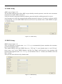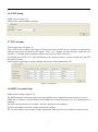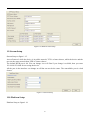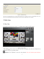
1
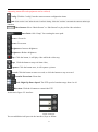
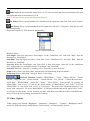
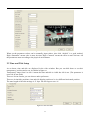
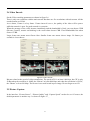
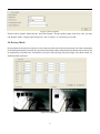
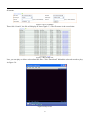
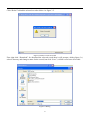
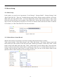
HD IP CAMERA
User manual
CONTENT
1 NETWORK SETUP ............................................................................................................................................................... 4
1.1 NETWORK STATUS ............................................................................................................................................................. 4
1.2 ETHERNET SETUP ............................................................................................................................................................... 6
1.3 WIFI SETUP ....................................................................................................................................................................... 7
1.4 ADSL SETUP ..................................................................................................................................................................... 8
1.5 DDNS SETUP ..................................................................................................................................................................... 8
1.6 UPNP SETUP...................................................................................................................................................................... 9
1.7 FTP ACCOUNT ................................................................................................................................................................... 9
1.8 SMTP ACCOUNT SETUP ..................................................................................................................................................... 9
1.9 STREAM SETUP ................................................................................................................................................................ 10
1.10 PLATFORM SETUP .......................................................................................................................................................... 10
2 MEDIA SETUP .................................................................................................................................................................... 11
2.1 PLAY VIDEO ..................................................................................................................................................................... 11
2.2 VIDEO CAPTURE .............................................................................................................................................................. 13
2.3 TIME AND TITLE SETUP .................................................................................................................................................... 14
2.4 VIDEO ENCODE ................................................................................................................................................................ 15
2.5 PICTURE CAPTURE ........................................................................................................................................................... 15
2.6 PRIVACY MASK ................................................................................................................................................................ 16
2.7 MEDIA STATUS ................................................................................................................................................................ 17
3 STORAGE SETTINGS........................................................................................................................................................ 17
3.1 STORAGE MANAGE .......................................................................................................................................................... 17
4.2 PLAY BACK ...................................................................................................................................................................... 17
3.3 RECORD SETUP ................................................................................................................................................................ 20
3.3.1 Basic Setup ............................................................................................................................................................... 20
3.3.2 Motion Detect Alarm Record ................................................................................................................................... 20
3.3.3 Motion Detect Alarm Capture .................................................................................................................................. 21
4.3.4 IO Alarm Record ...................................................................................................................................................... 21
3.3.5 IO Alarm Picture Capture ........................................................................................................................................ 22
3.3.6 Schedule Record....................................................................................................................................................... 22
3.4 STORAGE MANAGE .......................................................................................................................................................... 23
4.4.1 Unmount................................................................................................................................................................... 23
4.4.2 Format ..................................................................................................................................................................... 24
4 ALARM SETUP ................................................................................................................................................................... 25
4.1 MOTION DETECT ALARM SETUP ...................................................................................................................................... 25
4.2 VIDEO LOST ALARM ........................................................................................................................................................ 26
4.3 STORAGE FULL ALARM .................................................................................................................................................... 27
2
5 SYSTEM SETUP .................................................................................................................................................................. 27
5.1 SERIAL NUMBER AND KERNEL VERSION.......................................................................................................................... 27
5.2 ACCOUNT MANAGE ......................................................................................................................................................... 27
5.2.1 Add, Delete ............................................................................................................................................................... 27
5.2.2 User Group .............................................................................................................................................................. 29
5.3 TIME SETUP...................................................................................................................................................................... 30
5.4 LOG SETUP ....................................................................................................................................................................... 30
5.5 LOG VIEW ........................................................................................................................................................................ 31
5.6 CONFIG MANAGE ............................................................................................................................................................. 32
5.6.1 Configuration file management .................................................................................................................... 32
5.6.2 System Update ......................................................................................................................................................... 32
5.6.3 Restore Config ......................................................................................................................................................... 33
5.6.4 Reboot ...................................................................................................................................................................... 33
5.7 REGULAR MAINTENANCE ................................................................................................................................................ 34
5.8 LANGUAGE ....................................................................................................................................................................... 34
6 FREQUENTLY ASKED QUESTIONS .............................................................................................................................. 34
6.1 WHY CAN NOT ACCESS THE HD IP CAMERA BY IE? ...................................................................................................... 34
6.2 WHY THE PTZ CAN NOT CONTROL? ................................................................................................................................. 35
6.3 WHY CAN NOT SWITCH THE DATA? .................................................................................................................................. 35
6.4 WHY CAN NOT ACCESS THE HD IP CAMERA AFTER UPDATE? ....................................................................................... 35
6.5 NO SOUND AFTER CLICK “VOICE TALK” ........................................................................................................................... 35
3
1 Network Setup
1.1 Network Status
The connection schematic diagram for the entire system frame of HD IP CAMERA as figure 1.1.
Connect PC and HD IP CAMERA directly and set network parameter as follow: 1.the default IP address
is 192.168.0.123, net mask is 255.255.255.0, so you must add a IP address make the PC can access the
device (such as 192.168.0.88). 2. The net mask of the PC and the HD IP CAMERA must be same. Make
sure the direct network is through, as follow: “Start”-“Run”-enter “cmd” then enter “ping
192.168.0.123” and press “enter” on the keyboard. As figure 1.3, 1.4, and1.5. While the network is not
through, please check it.
Figure1.1 connecting schematic diagram
Figure1.2 enter “cmd”
Fiure1.3 enter “ping 192.168.0.123 –t”
Figure1.4 network is through
Figure 1.5 networks is not through
After then, power on. Enter the IP address in IE browser and press “enter”. Then it will display the
5
following interface as figure1.6, and then enter user name (admin) and password (123456) and click
“Login”.
Figure 1.6 Login interface
After enter system select and click “Network Setup”, it will display interface as figure 1.7, displaying
the IP address, gateway, net mask and DNS and so on. The detail information please refers to the actual
configuration.
Figure 1.7 Network status
1.2 Ethernet Setup
Ethernet setup as figure 1.8, all the parameter in the interface is needed to be reset. Also you can modify
the IP address by IP search (carried with UC2) or other tools. Make sure the IP address to be modified
and IP address of your PC are in the same network segment, and the IP address to be modified can not
be the same as the IP address of the PC in the network segment. After reset IP address the device will
reboot, then use the new IP address to access the HD IP CAMERA.
Net mask match with IP address to distinguish network address with local address, as 255.255.255.0. the
correct net mask is the premise for saving it.
Gate way is point between two networks such as router. So you can enter the router IP address.
DNS server address is host IP address running the domain server, which provide by network operators.
If enable the DHCP then it will obtain dynamic IP.
6
Figure 1.8 Ethernet setup
1.3 WIFI Setup
WIFI setup as figure 1.9. First you need to set wireless router called AP for short. All parameters in this
interface must be the same with the router setting. This interface only display with WIFI firmware of
HD IP CAMERA.
Figure 1.9 WIFI Setup
Note: only HD IP CAMERA with WIFI support function is the set item.
7
1.4 ADSL Setup
ADSL setup as figure 1.10
The username and password of the ADSL are provided by network operators, enter the correct username
and password, enable ADSL and save it.
It can run correctly on premise that the username, password and the confirm password is correct.
It will prompt error while the password and confirm password is incorrect. In order to verify the ADSL
is run correctly, you can enable DDNS and access the device by domain name. enable DDNS as figure
1.11 DDNS Setup)
Figure 1.10 ADSL Setup
1.5 DDNS Setup
DDNS setup as figure 1.11
First you must have a domain name. www.3322.org is recommended; please remember the username,
password and domain name.
Then enable DDNS, select the DDNS Server as “3322.org”. if your domain name is “test.3322.org”,
please enter “test” in the DDNS Domain, and the User Name and Password is the username and
password that applied in the www.3322.org. set the Refresh Time as 1 minute, then DDNS will work
after 1 minute.
Last you can access the device by domain name.
Figure 1.11 DDNS Setup
8
1.6 UPNP Setup
UPNP setup as Figure1.12.
UPNP run by external address and port.
Figure1.12 UPNP Setup
1.7 FTP Account
FTP account setup as Figure1.13.
First a FTP server is indeed. Then apply a FTP account from the FTP server (username and password).
And you must create four directory as “alarm”, “log”, “set”, “update” or other directory name, also you
can enter “./” then the entire document will be save in the root of the FTP server.
The default port of FTP is 21. The information of the interface must be correct to make sure the FTP
function run correct.
Alarm upload, log backup, configure backup and update can be uploaded by FTP.
Figure1.13 FTP Setup
1.8 SMTP Account Setup
SMTP account setup as figure1.14.
The SMTP function can run correctly on premise that the entire information in the interface is correct.
SMTP Server Address is the IP address of the SMIP server, the default port is 25, the authentication is
enabling.
The public network mail is no available. The show account can be anything.
The user mail address can not be empty and must be efficacy.
The CC mail address can be empty or other information. But only the correct address can receive mail.
9
Figure1.14 SMTP Account Setup
1.9 Stream Setup
Stream Setup as figure 1.15.
Access Protocol: while the device is in public network, TCP is a better choose, while the device and the
user are the same network then UDP is a better choose.
The default WEB port is 80. You can change it at will. But if you change it as 8080, then you enter
192.168.0.123:8080 for accessing the device.
All the port in the interface can change at will but can not be the same. The unavailable port is a bad
choose.
Figure1.15 Stream Setup
1.10 Platform Setup
Platform Setup as figure1.16.
10
Figure1.16 Platform Setup
The device can login platform server on the premise that the server IP and Server port is corresponding to the server.
The server account and password can enter them wt will. Of course enable login server is indeed.
2 Media Setup
2.1 Play Video
The window for playing video as Figure 2.1, it includes video window and PTZ control.
Figure2.1 Playing Video
Video window:Double click the real-time video then it will display video full-screen. Double click it
again then it will recovery default window.
PlayBack: Click "PlayBack" to enter the video playback.( Note: this function requires hardware
11
supporting mount SD card equipment can be realized)
Config: Click the "config" into the camera remote configuration items.
Quit: Click on the "exit" after the exit "confirm" dialog. Click the "confirm" returned the camera after login
interface.
Video Stream: Select “Main Stream” or “Sub Stream” to play in the video window.
Store Path: click “Setup” for resetting the store path.
Focus+: Focus far
Focus-: Focus near
Brightness+: Increase brightness
Brightness-: Reduce brightness
Play: Click the button, it will play video while the video stop
Stop: Click the button to stop real-time video
Capture: Click the button once, it will capture a picture
Record: Click the button to start to record, re-click the button to stop to record.
Zoom In/ Zoom Out: Zoom lens
Left- Right/Up-Down Speed: The PTZ speed of rotation range from 0 to 10
Direction: Click the 9 buttons to control the PTZ
As shown in figure 2.2 interface:
Figure 2.2 Preset
You can add/delete/call preset in the interface, steps as follow:
12
Add Preset: the preset number range from 1 to 255, first turn lens and enter preset number then turn
lens again and enter preset number as so on.
Note: it will not save the preset number greater than 65
Del. Preset: Select a preset number to be deleted from the option box and click “Del. preset” bottom
Call Preset: Select a preset number from the option box and click “Call preset” then the lens will
turn automatically.
As shown in figure 2.3 PTZ advanced functionality:
Figure2.3 Advanced function
Detail as follow:
Scan Begin: Turn lens and select “Scan Begin” in the “Orbit/Scan List” and click “Run”, then the
direction is a “Scan Begin”
Scan End: Turn lens again and select “Scan End” in the “Orbit/Scan List” and click “Run”, then the
direction is a “Scan End”
Scan On: When the “Scan Begin” and “Scan End” is done, then select “Scan On” in the “Orbit/Scan
List”, and then the lens will turn between “Scan Begin” and “Scan End”
Scan Off: While the “Scan On” is running, select “Scan Off” to stop “Scan On”
Orbit: Select “Orbit” and click “Run” then the lens will turn among all preset number.
Orbit Stop: Select “Orbit Stop” and click “Run” to stop orbit.
Advanced Function: Includes “Black/White”, ”Color”, ”Mirror Off/On”, “Freeze
Off/On”, “Steps Off /On”, “Screen Off/On”, “Lumen Off/On”, “ILL Off/On”, “Camera Reset/Switch”,
“B/W Auto”, “WB R/G/B/M”, “Initial Set”, “Menu”, “Track Off/On”, “Path On/Off”, for example for
“Black/White” and “Color”: we can see the preset number of “Black/White” and “Color” is 64, but
“Black/White” is “Set preset” and “Color” is “Call preset”. The work of the advanced function is “set
preset” and “call preset”. So select “Black/White”, it will play in black/white mode, while select “Color”
it will play in color mode. All the function are same with them, but different camera with difference,
please refer to the corresponding user manual of camera.
2.2 Video Capture
Video capture setup include “Brightness”, “Saturation”, “Sharpness” , “Contrast”, “Backlight Control”
and so on , different country with different “Video Format”, in China just PAL format.
13
Figure 2.4 Video Capture Setup
When set the parameter values can be manually input values; also click “default” is a good method.
High “Saturation” means color is more obvious; High “Contrast” means the effect is more obvious. All
the parameters must according to the physical environment.
2.3 Time and Title Setup
As we know, time and title are displayed in the video window. But you can hide them or set their
transparency, position and so on. As shown in figure2.5.
Transparency range from 0 to 100. 0 means the time and title is visible but 100 is not. (The parameter is
reserved, do not work)
There are 8 time format, you can choose under preference.
There are 4 time/title positions, time and title display position to be in a different horizontal position.
The max length of the title message is 31 byte. Do not forget to save it!
Figure2.5 Time and Title
14
2.4 Video Encode
Set the Video encoding parameters as shown in figure 2.6.
There is only one resolution with the main stream. But there are five resolutions with sub stream. All the
encode format are H.264.
As we know, I frame is a key frame. I frame interval is too e, the quality of the video will be poorer
while the network is poor. So good network is a promise.
When the message of the video increase imminently and the bandwidth is fixed, you can choose VBR
(Bit rate Control), mosaic and shaking is the result when choose CBR. Fixed bandwidths first when
choose CVBR.
Larger frame rate means more fluent video. Smaller frame rate means slower image. 20 frames per
seconds is a best choose.
Figure2.6 Video Encode
Bit rate related to the speed of video transmission. The speed of D1 is at least 1000 kbps, but CIF is only
50.But when the resolution is 1080P, the “Bitrate” at least 6000 kbps and when the resolution is QVGA,
the “Bitrate” at least 300 kbps. The bit rate is too small result in poor image. Do not forget to save it!
2.5 Picture Capture
In the interface, “Picture Source”, “Picture Quality” and “Capture Speed” need to be set. Of course, the
default parameter is another way. As shown in figure 2.7
15
Figure2.7 Picture Capture
Picture source include “Main Stream” and “Sub Stream”; Picture quality range from 20 to 100, you also
can drag the slider; Capture speed between 1 and 2, means 1 or 2 pictures per second.
2.6 Privacy Mask
Privacy Mask set as shown in figure 2.8, only need to set the size of the area and keep out of the coordinates
of the block parameters can block out any part of the image. Main code stream and stream has 4 can be set
up respectively occluded area, coordinates, and can be set manually, the input integer value block width, set
coefficient after click save.
Figure2.8 Privacy Mask
16
2.7 Media Status
In this interface, the main duty is display the status of video encodes. As shown in figure 2.9.
Figure2.9 Media Status
3 Storage Settings
Note: This function need hardware support, some models not this function.
3.1 Storage Manage
In this interface, just only show the statue of the storage, as figure 3.1
Figure3.1 Storage Information
4.2 Play Back
First you can set the query conditions about querying record as figure 3.2. Be careful, “End Time” can
not more 7 days than “Start Time”. Record type include schedule, motion detect, alarm and all type;
Media type include audio & video, video and picture; video stream include main stream, sub stream and
17
all stream.
Figure3.2 Query Condition
Then click “Search”, the file will display in list as figure 3.3. The file name is the record time.
Figure3.3 Record File List
Last, you can play or delete or download the files. Click “Download” behind the selected record to play.
As figure 3.4.
Figure3.4 Play record
18
Click “Delete” behind the selected record to delete. As figure 3.5.
Figure3.5 Delete record succeeded
First right click “Download” for download the selected record then it will prompt a dialog figure 3.6,
select a directory and change a name for the record, last click “Save”, well the record save succeeded.
Figure3.6 Dialog
19
3.3 Record Setup
3.3.1 Basic Setup
In this option, you need to set 4 parameters “Local Storage”, “Storage Media”, “Storage Strategy” and
“Max Time Each File”. There are 7 methods about storage media. Storage strategy includes “Overwrite
When Full” and “Stop When Full”. “Overwrite When Full” means when all the storage is full, it will
delete the old record and go on recording; “Stop When Full” means when all the storage is full, it will
stop to record. The max time of each file is 10 or 20 or 30 minutes. But in fact the max time of each file
is 10 minutes, so “Max Time Each File” does not work there.
Figure3.7 Basic Set
3.3.2 Motion Detect Alarm Record
Motion detect alarm record means it will start recording when motion alarm is coming.
Video stream include “Video Main Stream” and “Video Sub Steam”. The former means record with
main stream; the latter means record with sub stream. Media type includes “Audio And Video” which
means record with audio and video and “Video” which means record without audio. Prerecord time
means it will prerecord when motion alarm is coming, the max time is 5 seconds and the min time is 1
seconds. The record time range from 10 to 600 seconds. Also you can set the motion alarm record
upload to FTP or send a email to you. Do not forget to save it!
Figure3.8 Motion Detect Alarm Record
20
Figure3.9 Save
3.3.3 Motion Detect Alarm Capture
Another way for “motion detect” alarm is capture. Except precapture and capture time, the other
parameter are the same with the parameter of “Motion detect alarm record”. “Precapture” is the same
meaning with”Prerecord”, “Capture time” means the time of capturing.
Figure3.10 Motion Detect Alarm Picture Capture
Before enable “Motion Detect Alarm Capture”, you must ensure “Picture Capture Setup” enabled.
Figure3.11 Picture Capture Setup
4.3.4 IO Alarm Record
The setup method is the same with “Motion Detect Alarm Record”. The condition of alarm is not the
same with “Motion detect alarm”, it will alarm when the IO is changing.
21
Figure3.12 IO Alarm Record
3.3.5 IO Alarm Picture Capture
The same method with “Motion Detect Alarm Capture”.
Figure3.13 IO Alarm Picture Capture
3.3.6 Schedule Record
Except “Video Stream” the other parameter is the same with “Motion Detect Alarm Record”, Video
Stream include “Snapshot” which means it will take photo during the schedule record time, “Video Main
Stream” and “Video Sub Stream”.
Figure3.14 Schedule Record
22
Figure3.15 Time Table
You can set time span for schedule record. The max number of time span is 24. And the time for
schedule record and motion detect alarm record can not be the same.
3.4 Storage Manage
4.4.1 Unmount
“Unmount” means remove the storage from the device. In order to prevent data destruction. When click
“Unmount” it will pop-up a dialog as figure 4.17 and click “OK”, it will remove the storage. It prompt a
dialog as figure 4.18 means remove successfully.
23
Figure4.16 Unmount
Figure4.17
Figure4.18 Unmount
4.4.2 Format
Select the storage to be formatted and click “Format” button, then it will prompt two dialogs figure 4.19,
click “OK” to format or click “Cancel” to cancel it.
24
Figure4.19 Format
4 Alarm Setup
4.1 Motion Detect Alarm Setup
In this interface too many parameters need to be set, such as sensitivity, threshold, block count (checking
area), night time span, night sensitivity, night alarm threshold and so on.
Sensitivity range from 1 to 100, 1 is the most insensitive; 100 is the most insensitive. Alarm threshold
also range from 1 to 100, 1 is most likely to alarm; 100 is least likely to alarm.
As figure 4.1 we know, alarm is enabled, sensitivity is 100; alarm threshold is 10. Night time is also
enabled, time span from 0:00 to 24:00.
Figure4.1 Motion Detect Alarm
25
Also you can set alarm time as following. The max number of time span is 23. And the time for schedule
record and motion detect alarm record can not be the same. Different time spans in different colors.
Figure4.2 Motion Detect Schedule
Each time span can not conflict, otherwise it will prompt figure 4.3:
Figure4.3 Time Span Error
4.2 Video Lost Alarm
Too many reasons can cause video lost, such as disconnect video cable. In this case, we can enable
“Video Lost alarm” for reminding. At the same time, many parameters need to be configured, as figure
4.4. Alarm output is another way for reminding “Video lost”. But you need to enable it and configure
parameters for it.
Figure4.4 Video Lost
26
4.3 Storage Full Alarm
If the storage with HD IP CAMERA then you can enable “Storage Full Alarm”, it will alarm when the
usage of the storage close to 100%. In this page, alarm rate is usage of storage such as 95, it means it
will alarm when the usage is 95%. Alarm output is similar to the other alarm output before.
Figure4.5 Storage Full Alarm
Note: this function requires a mount SD card hardware to achieve.
5 System Setup
5.1 Serial Number and Kernel Version
In this page you can view kernel version, serial number, file system version and web page version.
Figure 5.1.
Figure5.1 System Info
5.2 Account Manage
5.2.1 Add, Delete
Add and delete user for accessing the HD IP CAMERA in this page. The username can’t be empty, only
letter and number are allowed. The length of username is 30 bytes.
Up to 10 users. The entire users will display in the “All Accounts” table.
27
Figure5.2 Account Manage
Click on the “Add User” and enter added “User name” and “Password”, then click “Save”, will pop-up a
dialog, click the “OK", add a new user successfully figure 5.3.
Figure5.3 Add User
Click “delete user”, and select users to delete, then click “save”, will pop-up a dialog, click the “OK”,
then the user was deleted figure 5.4.
28
Figure5.4 Delete user
5.2.2 User Group
Different user can have different permissions. Click “Modify User” to modify the user or disable it or
modify password.
There are three different types of user group, viewer, operator and administrator. As a viewer, you only
can view network status, media setup, storage info, serial number and so on. As an operator, you only
can operate but can’t mange. Of course, administrator can do anything.
If you want to modify a user as an operator. First you need to select it and click “Modify User”, then the
lower left corner will show the user information, last you need to select “User Group” in “User Group”,
and click the "save", will pop-up a dialog, click the "ok", then change successful figure5.5.
Figure5.5 Modify User
29
5.3 Time Setup
There are two type of update mode in this system. One is “Manual”, the other is “NTP Server”.
“NTP Server” will choose a same time zone with the client automatically. NTP IP is
“time.windows.com”. NTP port can be a valid port and “Refresh Time” can range form 60 to 999999.
Save all parameter, then it will update as a network clock.
“Manual” means update time manually. You need to enter time, time zone and date manually.
It will reboot after re-set time
Figure5.6 Manual
Figure5.7 MTP Server
5.4 Log Setup
In this page, you can set “output log type” according to actual needs. There are many types such as
“Debug”, “Run”, “Error”, “Operation”, “Alarm”, “Statistic” and “Common”. Saving days range from
7-30 days. Store strategy includes “Overwrite When Full” and “Stop When Full” which is the same with
“Storage Strategy” of record basic setup. Also you can backup the logs by two methods, one is “Update
to Email”, and the other is “Update to FTP”. But first you need to enable “Auto Backup”.
30
Figure5.8 System Log Setup
5.5 Log View
Click on "query" in figure 5.9, the system will list out all the log files.
Users can log files for download access, delete log files, empty log can be one-time permanent to empty
all of system log.
Figure5.9 Log File Manage
The downloaded file, select to download the log file, click on the download, file will be downloaded to
the local notepad or local store path specified.
After deleting files, select file, select the delete operation after confirmation dialog will pop up as shown
in figure 5.10, delete the log file after click the “OK”.
Figure5.10 Delete the log file confirmation dialog
31
5.6 Config Manage
5.6.1 Configuration file management
When all parameters have been modified, you can download the configuration file and save it. Then you
do not need to modify again only upload configuration file. Also you can view the configuration file in
this page.
Uploaded, click on "browse" and specify to upload the configuration file path, click "upload". System
will give you the prompt of upload success, successful upload system will automatically restart figure
5.11.
Figure5.11 Upload and Download
5.6.2 System Update
When the software needs to be update, you can update firmware which would be provided by device
suppliers, as shown in figure 5.12.
Figure5.12 Upload and Download
As shown in figure 5.13, click the firmware file to the right of the "Loading", as shown in figure 5.14 the
pop-up dialog "choose file ". As figure 5.13 in the dialog select upgrade file click on the "open", then
click on the "upgrade" button in the figure 5.12, the system began to escalate.
As shown in figure 5.13, click the firmware file to the right of the "Loading", as shown in figure 5.14 the
pop-up dialog " choose file". As shown in figure 5.13 in the dialog select upgrade file click "open", then
click the "upgrade" button shown in figure 5.12, the system begins to upgrade, after upgrade is complete,
as shown in figure 5.15 a pop-up tip " Update Succeeded "
As shown in figure 5.15, after click "OK" to Reboot the HD IP CAMERA.
Figure5.13 System Update
32
Figure5.14 Select firmware
Figure5.15 Update Succeeded
Note: the device can not be power off when updating. And the firmware must be correct.
5.6.3 Restore Config
“Restore Config” means restore factory settings. All the parameters set by you will be last. There will be
confirming figure 5.16, click “OK”. All the parameters restore to default configure and reboot
automatically
Figure5.16 Restore Config
5.6.4 Reboot
When you want to reboot the device, then you can click “Reboot”. It will save all parameters and
configuration. And it also will prompt a dialog to confirm. The restart time is about 75 seconds. Click
“Cancel” to cancel reboot.
33
Figure5.18 reboot
5.7 Regular Maintenance
User can set the device automatically reboot the system, as shown in figure 5.19.
Figure5.19 Regular Maintenance
5.8 Language
There are three languages “Simplified Chinese”, “Traditional Chinese” and “English”. You can choose it
by yourself and save it.
Figure5.20 Language settings
6 Frequently Asked Questions
6.1 Why can not access the HD IP CAMERA by IE?
There maybe 4 reasons: NO.1, the network unreasonable. First you can connect network by PC, check
the network cable is good. And check the network between the HD IP CAMERA and the PC is good as
figure 1.3. NO.2 the IP address of the HD IP CAMERA is occupied by other device or PC. You can
connect the HD IP CAMERA with your PC directly, and modify the IP address. NO.3 the HD IP
34
CAMERA maybe in other network. Check the IP address and net mask. NO.4 unknown. You can restore
the HD IP CAMERA to default configuration.
6.2 Why the PTZ can not control?
Two reasons: NO.1 the PTZ protocol or address port or baud rate is incorrect, and then you need to
modify the parameter according to the actual application as figure 3.1. NO.2 the PTZ cable is
disconnected, and then you need to re-connect the cables.
6.3 Why can not switch the data?
Possible cause:
NO.1 Two-Switches. Whether the IP address is correct or not?
NO.2 Three-Switches. Whether port and physical address bindings?
NO.3 Firewall
First you can try to connect the HD IP CAMERA as figure 1.3. If the network timeout, you need to
check the port mapping or re-set the firewall.
6.4 Why can not access the HD IP CAMERA after update?
Clean browser cache. Steps: open IE, click “Tools” and select “Internet Options”, then you can see
“Temporary Internet files” and click “Delete Files”, it will prompt a dialog you need to check “Delete all
offline content” and click “OK”. Also you can click “Start” and select “Run” then enter “cmd”, enter
“arp -d” in “Command Prompt” interface. Re-access the HD IP CAMERA.
6.5 No sound after click “Voice talk”
First confirm the “Voice talk” start succeeded. Then check the HD IP CAMERA connect audio input
device. Last check the wheat and headphones is good.
35