1
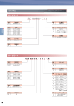
FUJI SERVO SYSTEM
MEH556e
Smart servo for smart users
High Value
Higher cost-performance with
original main features.
High Performance
High-speed, high-precision positioning
- Frequency response 1500Hz
- Max motor speed 6000r/min
- High-resolution encoder
18-bit ABS/INC 262,144 pulses
20-bit INC 1,048,576 pulses
High Usability
New servo operator offers improved usability.
High Performance
High Value
High
h Usability
b l
Smart adjustment
Advanced auto-tuning function and robust performance for unprecedented smart adjustment.
Smart design
Inherits the main features of ALPHA5. Highly adaptable smart design.
Smart operation
The new Servo Operator allows smart operation anytime anywhere.
C
2
O
N
T
E
N
T
S
Smart Concept
2
External Dimensions
15
ALPHA5 Smart Features
3
Service Network
23
Application Examples
6
Software
24
ALPHA5 Product Family
7
Capacity Adoption
25
Model Codes
8
Configuration Diagram/Peripheral Equipment
26
Combination Table
9
Option
27
Servo Amplifier Specifications
10
Model List
28
Connection Diagram
11
Product Warranty
31
Servomotor Specifications
12
Reference Material/Related product(V8)
32
ALPHA5 Smart Features
Feature 1
| Smart Adjustment
New auto-tuning function
ALPHA5 Smart Features
Optimal tuning even with low-rigidity devices.
Easy adjustment even for long belt mechanisms, gears with considerable backlash, and rack and pinion mechanisms.
Before...
With low rigidity,
response cannot be
improved due to
resonance.
Command speed
Feedback speed
Torque
With the Smart...
The Smart allows
response to be
improved without
generating resonance
even with low rigidity.
This enables greater
resistance to
disturbance (or impact
load).
Command speed
Feedback speed
Torque
! POINT1 ! POINT2
! POINT1 Resistance to impact load
! POINT1 ! POINT2
! POINT2 Low machine resonance
Superior stability
Smooth, stable operation even with changes due to wear or variation* among devices.
Before...
With the Smart...
If the rigidity changes or varies among devices the motor oscillates, causing the machine resonance.
The motor runs smoothly without oscillating, even with varying rigidity.
* Variations in device rigidity such as belt tension or parts.
3
ALPHA5 Smart Features
Feature 2
| Smart Design
PTP positioning
ALPHA5 Smart Features
Positioning function built in
as standard
Sophisticated
PLC
No external units or
special equipment required
for positioning
Positioning
function
Compact type
PLC
Conventional
servo system
equipped with built-in
positioning function
3-in1 functionality
Three operations via one unit:
- Positioning via Modbus-RTU communications (immediate value data)
- Positioning via Di/Do signal (positioning data 15 points*)
- Position, speed, and torque control via pulse/analog input
Servo amplifier
Modbus-RTU
Immediate data 1...n
Position
Speed
Acceleration time
Deceleration time
...
Host controller
(Immediate value data)
allows
unlimited settings!
Di/Do
Di/Do
Pulse/analog
* Modbus-RTU enables positioning data
editing and number command using
the internal amplifier settings.
Di/Do signal
(Positioning data number)
Pulse/Analog command
Amplifier internal setting
Positioning data 1
PTP
Position
Amplifier internal setting
positioning
Speed
Positioning data 2
Acceleration time
computing
Position
Amplifier
Deceleration
time internal setting
part
... Speed
Positioning data 15
Acceleration time
Maximum
15
points
Position time
Deceleration
can be set
... Speed
Acceleration
time
the amplifier!
inside
Deceleration time
...
Servo control part (position/speed/torque)
Simple operation via Modbus-RTU communications
Modbus-RTU communications enables PTP positioning, parameter editing, and the use of various monitors.
Just connect an HMI, general-purpose PLC, or PC controller directly to the servo amplifier.
Startup command
HMI
Startup command
General-purpose
PLC
[Now, that’s handy!]
Broadcast function enables
simultaneous start up of
multiple servo amplifiers.
Max. 31 units
can be
connected.
Startup command
PC controller
Products of all makers compatible with Modbus-RTU
4
Any HMI, general-purpose PLC, or PC controller compatible with
Modbus-RTU can be connected to servo amplifier easily regardless of maker.
Long-life design
Regulatory compliance
Servo amplifier parts designed to
last longer
Global Comptibility
The standard model complies with CE marking, UL/cUL
and TÜV.
Electrolytic capacitor: 10 years
* Operating conditions
- Ambient temperature: Average 30°C/year
- Load factor: Within 80%
- Operation rate: Within 20 hours/day
* Some of the models are in the process to be certisfied.
RoHS Directive
Compliant with the European Restriction of Hazardous
Substances (ROHS) Directive. The use of six hazardous
substances has been reduced for a more
environmentally-friendly servo system.
Easy ABS battery replacement
ABS backup battery can be mounted
on front face of servo amplifier for
easy replacement
Feature 3
<Six hazardous materials>
Lead, mercury, cadmium, hexavalent chromium, polybrominated
biphenyl (PBB), polybrominated diphenylether (PBDE)
| Smart Operation
New servo operator
New handy-sized portable servo operator now available
On site
Parameter
copy
Positioning
data copy
Test run
function
Monitoring
function
Allows test run operations
such as reading, writing,
teaching, and saving
parameters to be carried out
easily on site.
In an office
Alarm
history copy
Parameter
copy
Without
a converter
Conventional
onvention
cost
costly
converter
con erter
Positioning
data copy
Alarm
history copy
Back at the office, you can
check or edit the data saved
in the memory on site.
RS-485
conversion
function
Equipped with two USB ports (B and
miniB). Servo operator can be used
as an RS-485 communications
converter between the PC and the
servo amplifier.
5
ALPHA5 Smart Features
Cooling fan: 10 years
Application Examples
Packaging Machine
Mark signal
Modbus-RTU
Application Examples
HMI
RS-485
SM1(feed axis)
Compact PLC
SM2(cut axis)
Interrupted
travel amount
Automatic operation
(cut length feed)
Mark signal
(interruption signal)
Startup
Positioning completion
1. Servo amplifier features a built-in positioning function
Features
The servo amplifier’s positioning data enables film feeding without the positioning controller.
2. Less wiring required
Wiring requires fewer man-hours as basic positioning is carried out via Modbus-RTU communications.
3. Interrupted positioning
The interrupted positioning function allows a specified amount of travel after the mark is detected for more
precise mark operation.
Conveyor
6
XY Table
Workpiece feeder,
carrier, etc.
Engraving machine,
2D positioning unit, etc.
<Key Points>
<Key Points>
- The positioning data enables
positioning without a PLC.
- The positioning data enables
positioning without a PLC.
- Enables simultaneous operation.
- Enables rapid acceleration/deceleration and
high-speed operation.
- Enables rapid
acceleration/deceleration and
high-speed operation.
- Enables high-accuracy positioning.
- Enables high-accuracy positioning.
- High-tact operation mode allows high-frequency operation.
- Trace operation mode allows optimal operation.
ALPHA5 Product Family
ALPHA5 Series Lineup
Coming soon.
Applicable motor capacity(kW)
Type
Voltage(V)
0.05 0.1 0.2
0.4
0.5 0.75 0.85 1.0 1.3
1.5
2.0
3.0 4.0 5.0
Servo Amplifier
ALPHA5 Product Family
3-phase
200V
ALPHA5 Smart
Single-phase
200V
3-phase
200V
ALPHA5 VV type
Single-phase
200V
Single-phase
100V
General-purpose
interface
3-phase
200V
ALPHA5 VS type/
ALPHA5 LS type
Single-phase
200V
Single-phase
100V
High speed serial bus
(SX bus)
Servomotor
GYS motor
Ultra-low inertia
GYC motor
Low inertia
GYG motor
Middle inertia
GYG motor
Middle inertia
GYB motor
Middle inertia
GYS motor
3000r/min
200V series
(11 models)
Max. speed
0.75kW or less: 6000r/min
1.0kW or more: 5000r/min
100V series
(4 models)
GYC motor
3000r/min
Max. speed
0.75kW or less: 6000r/min
1.0kW or more: 5000r/min
GYG motor
2000r/min
Max. speed
3000r/min
GYG motor
1500r/min
Max. speed
3000r/min
GYB motor
3000r/min
Max. speed
6000r/min
200V series
(7 models)
200V series
(5 models)
200V series
(3 models)
200V series
(3 models)
7
Model Codes
Servo Amplifier
RYH 201 F 5 - V V 2
Code
RYH
Code
[Basic type]
ALPHA5 Smart series
Code
2
[Input voltage]
3-phase 200V
[Applicable motor output]
Code
[Upper interface]
General-purpose interface
(pulse, analog voltage)
20×101=200W, 100W, 50W
40×101= 400W
75×101=750W, 500W
Model Codes
201
401
751
152
15×102=1.5kW, 1.0kW, 850W
Code
202
20×102=2.0kW
V
V
[Major functions]
Position, speed
and torque control
2
302
30×10 =3.0kW
Code
F
[Series]
1500 to 3000r/min series
Code
5
[Order of development]
5
Servomotor
GYS 500 D 5 - H B 2 - B
Code
GYS
GYC
GYG
[Basic type]
Ultra-low inertia
Low inertia
Middle inertia
Code
[Rated output]
50×100=0.05kW
10×101=0.1kW
20×101=0.2kW
40×101=0.4kW, 0.375kW
50×101=0.5kW
75×101=0.75kW
85×101=0.85kW
10×102=1.0kW
13×102=1.3kW
15×102=1.5kW
20×102=2.0kW
30×102=3.0kW
500
101
201
401
501
751
851
102
132
152
202
302
Code
D
C
B
[Rated speed]
3000r/min series
2000r/min series
1500r/min series
Code
5
[Order of development]
5
Code
[Brake]
Not provided
Provided
Code
[Input voltage]
2
3-phase 200V
Applicable motor
Code
[Oil seal/shaft]
A
Without an oil seal,
straight shaft with a key
B
Without an oil seal,
straight shaft without a key
C
Without an oil seal,
straight shaft with a key,
tapped
E
With an oil seal,
straight shaft with a key
F
With an oil seal,
straight shaft without a key
G
With an oil seal,
straight shaft with a key,
tapped
GYS, GYC,
GYG
: Standard item
: Semi-standard item
: Made-to-order item
* Applicable with GYS and GYC motors of 0.1kW
or less
Code
H
R
8
Blank
B
[Encoder]
18-bit ABS/INC
20-bit INC
Combination Table
Servo Amplifier / Motor
Applicable
motor
Applicable
motor
capacity
Servo amplifier
RYH401F5-VV2
GYC motor
Low inertia
GYG motor
Middle inertia
GYG motor
Middle inertia
3000[r/min]GYS
Ultra-low inertia
Brake: Not provided
3000[r/min]GYC
Low inertia
Brake: Not provided
2000[r/min]GYG
Middle inertia
Brake: Not provided
1500[r/min]GYG
Middle inertia
Brake: Not provided
(incorporated)
(incorporated)
(incorporated)
(incorporated)
GYG501C5-□□2(-B)
GYG501B5-□□2(-B)
50W
GYS500D5-□□2(-B)
100W
GYS101D5-□□2(-B)
GYC101D5-□□2(-B)
200W
GYS201D5-□□2(-B)
GYC201D5-□□2(-B)
400W
GYS401D5-□□2(-B)
GYC401D5-□□2(-B)
500W
Combination Table
RYH201F5-VV2
GYS motor
Ultra-low inertia
RYH751F5-VV2
750W
GYS751D5-□□2(-B)
GYC751D5-□□2(-B)
GYG751C5-□□2(-B)
GYG851B5-□□2(-B)
850W
RYH152F5-VV2
1.0kW
GYS102D5-□□2(-B)
GYC102D5-□□2(-B)
GYG102C5-□□2(-B)
1.5kW
GYS152D5-□□2(-B)
GYC152D5-□□2(-B)
GYG152C5-□□2(-B)
RYH202F5-VV2
2.0kW
GYS202D5-□□2(-B)
GYC202D5-□□2(-B)
GYG202D5-□□2(-B)
RYH302F5-VV2
3.0kW
GYS302D5-□□2(-B)
GYG132D5-□□2(-B)
9
Servo Amplifier Specifications
Common specifications
Servo Amplifier Specifications
Applicable motor rated speed
Applicable motor output
[kW]
Amplifier type
RYH
F5-VV2
Outer frame number
Mass
[kg]
Protective construction / cooling
Power supply
Phase
Voltage / frequency
Allowable voltage fluctuation
Control system
Max voltage for regene- Built-in resistor
rative resistance [W] External resistor
Feedback
Overload capability
Speed fluctuation Load fluctuation
ratio*
Power supply fluctuation
Temperature fluctuation
Capability and
Speed control
function
Number of position data sets
VV type
Positon control
Torque control
Accessory functions
Protective function
(Alarm display)
Operation and display section of main body(keypad)
Working
Installation place
conditions
Temperature / humidity
Vibration /
shock resistance
Standards
0.05
0.1
201
1a
0.2
0.4
401
1b
3000r/min
0.75
1.0
1.5
751
152
2a
2b
1.2
1.3
2.0
202
3a
3.0
302
3b
2000r/min
1.0
1.5
751
152
2a
2b
1.2
1.3
Open / mechanical cooling
Single-phase, 3-phase
3-phase
0.5
0.75
2.0
202
3a
2.2
0.5
751
2a
1.2
1500r/min
0.85
1.3
152
202
2b
3a
1.3
2.2
0.8
2.2
Open / natural cooling
Single-phase, 3-phase
3-phase
Single-phase, 3-phase
3-phase
200 to 240VAC 50/60Hz
3-phase : 170 to 264 VAC, Single-phase : 180 to 264 VAC
Fully-digital sinusoidal PWM drive
−
20
30
20
30
20
30
17
50
260
50
260
50
260
INC 20bit/rev, ABS/INC 18bit/rev
300% / 3 sec.
Within ± 0.01% (load fluctuation 0 to 100% at rated operation speed)
0% (power supply fluctuation -10 to +10% at rated operation speed)
Within ± 0.2% (25 ± 10°C at rated operation speed)
Closed loop control with speed adjuster, acceleration/deceleration time setting, manual feed rate/max. rotation speed, speed command zero clamp, etc.
15-point (position, speed, acceleration/deceleration time setting, timer, M code and various statuses)
Closed loop control with position adjuster, electronic gear, output pulse setting, feed forward, homing, interrupt positioning, auto startup, etc.
Closed loop control with current adjuster (proportional open loop control of current and torque), torque limit, speed limit at torque control, etc.
Easy tuning, profile operation, sequence test mode, auto tuning, auto notch filter, vibration suppressing online learning, etc.
Over Current (oc1, oc2), Over Speed (oS), High Voltage (Hu), Encoder Trouble (Et1, Et2), Circuit Trouble (ct), Data Error (dE),
Combination Error (cE), Resistor Tr Heat (tH), Encoder Communication Error (Ec), Cont (CONTrol signal) Error (ctE), Over Load (oL1, oL2),
Power Low Voltage (LuP), Resistor Heat (rH1, rH2, rH3), Over Flow (oF), Amp Heat (AH), Encoder Heat (EH), Absolute Data Lost (dL1, dL2, dL3),
Absolute Data Over Flow (AF), Initial Error (iE)
4-digit alphanumeric display with 7-segment LED 4 operation switches (MODE, SET, UP and DOWN)
Indoors at altitude ≤ 1000m, free from dust, corrosive gases and direct sunlight
In case of compliance with CE marking: pollution degree 2, over voltage category III
-10 to 55°C/10 to 90%RH (without condensation)
Vibration resistance: 3mm: 2 to 9Hz or less, 9.8m/s2: 9 to 20Hz or less, 2m/s2: 20 to 55Hz or less, 1m/s2: 55 to 200Hz or less
Shock resistance: 19.6m/s2 (2G)
UL/cUL (UL508c), CE marking (low voltage directive EN61800-5-1), RoHS directive (Some of the models are in the process to be certisfied.)
*This value represents the average value of the speed fluctuation that is generated from load fluctuation, power supply fluctuation, and temperature fluctuation as the percentage to the rated rotation speed.
Interface specifications
Item
Command interface
Positioning function
Position control
Speed control
Torque control
Communication interface
Terminal name
Pulse input
Pulse output
Analog monitor voltage
output
Symbol
CA,*CA
CB,*CB
PPI
FFA,*FFA
FFB,*FFB
FFZ,*FFZ
FZ
M5
MON1
MON2
Common for sequence
I/O
Sequence input signal
M5
COMIN
COMOUT
CONT1 to
CONT5
Sequence output signal
COMIN
OUT1 to
OUT3
Analog voltage input
(for speed and torque control)
COMOUT
VREF
TREF
M5
10
Specifications
RS-485 (Modbus-RTU), Di/Do
Pulse input
Analog voltage input
Analog voltage input
Two RS-485 ports (for parameter editing and monitor)
Fuji’s original protocol Modbus-RTU
9600/19200/38400/115200 bps, connection of max. 31 units
Specifications
Differential input: max. input frequency ≤ 1.0MHz
Open collector input: max. input frequency ≤ 200kHz
(in case of signals at 90-degree phase difference, the above relationship is true for the four-fold frequency.)
Pulse format
Command pulse/Command direction
Forward/Reverse pulse
Select one of these formats with a parameter setting.
Two signals at 90-degree phase difference
Pull-up power input at open collector input (24VDC ± 5%)
Differential output: max. output frequency ≤ 1MHz
Two signals at 90-degree phase difference
Pulse output count setting n (pulses/rev): 16 ≤ n ≤ 262144
Differential output: 1 pulse/rev
Open collector output: 1 pulse/rev
Reference potential (0V)
0V to ± 10VDC
Resolution: 14bits / ± full scale
The output data depends on internal parameter.
Reference potential (0V)
Common for sequence input signal
Common for sequence output signal
12VDC-10% to 24VDC+10%
Current consumption 8mA (per contact; used at circuit voltage of 12 to 24VDC )
Function of each signal depends on parameter setting
Compatible with both sink and source input methods
Reference potential
30VDC / 50mA (max.)
Function of each signal depends on parameter setting
Compatible with both sink and source output methods
Reference potential
Speed command voltage input
Input range: from -10 to 0 to -10V, input impedance 20kΩ Resolution: 15 bits / ± full scale
Torque command voltage input
Input range: from -10 to 0 to +10V, input impedance 20kΩ Resolution: 14 bits / ± full scale
Reference potential (0V)
Connection Diagram
VV type
External regenerative resistor
No internal regenerative resistor
The external regenerative resistor is connected between
RB1 and RB2.
Sample: frame 1
PN junction
4
1
2
3
N(-) P(+) RB1 RB2
Commercial power supply
3-phase/single-phase 200V
TB2
TB1
L1
L2
TB1
L3
CN3A
USB
U
1U
V
2V
W
3W
CN2
4E
P5 1
M5 2
SIG+ 5
SIG- 6
BAT+ 3
BAT- 4
7 P5
8 M5
5 SIG+
4 SIG1 BAT+
8 P5
7 M5
6 *TXD
5 RXD
4 *RXD
3 TXD
2 M5
1 P5
RS-485
M
PG
2 BAT3 FG
*1
Servomotor
*1
Connection Diagram
CN3B
PC loader
Servo operator
Connector CN3B
No terminal resistor is
required when it is used
as a terminal.
8 NC
7 M5
6 *TXD
5 RXD
4 *RXD
3 TXD
2 M5
1 NC
CN5
BAT+ 2
ABS backup battery
DC3.6[v]
BAT-(M5) 1
CN4
CN1
Open Collector Connection
(DC24V Power supply)
22
13
18
13
Analog speed
command input
Analog torque
command input
Upper PLC
VREF
M5
TREF
M5
19 PPI
7 CA
8 *CA
20 CB
21 *CB
DC24V
Power supply
for pulse open collector input
*2
*1
Open Collector Connection
(DC12V Power supply)
Sequence
input
R=300Ω
1/4W
R
19 PPI
7 CA
R
8 *CA
R
20 CB
R
21 *CB
DC12V
7
8
20
21
*1
Wiring length:2m or less
Upper PLC
19 PPI
Pulse input
(differential)
*1
MON1 1
MON2 2
M5 3
M5 4
CA
*CA
CB
*CB
*1
FFA 9
*FFA 10
FFB 11
*FFB 12
FFZ 23
*FFZ 24
FZ 25
M5 26
Oscilloscope
A-phase pulse output (differential)
B-phase pulse output (differential)
Z-phase pulse output (differential)
Z-phase pulse output
(Open collector)
1 COMIN
2
3
4
5
6
CONT1
CONT2
CONT3
CONT4
CONT5
OUT1 15
OUT2 16
OUT3 17
Sequence output
COMOUT 14
Servo amplifier
Wiring length:2m or less
*1: Connect the shield to the connector shell of CN1 and CN2. The connector shell is at the ground potential.
*2: When connecting the open collector, the wiring length should be 2 m or less.
Caution
The diagram shown above is given as a reference for model selection.
When actually using the selected servo system, make wiring connections according
to the connection diagram and instructions described in the user's manual.
11
Servomotor Specifications
GYS motor
■Standard specifications
Motor type
(-B) indicates the brake-incorporated type.
Rated output
[kW]
Rated torque
[N . m]
Rated speed
[r/min]
Max. speed
[r/min]
Max. torque
[N . m]
Inertia
[kg . m2]
( ) indicates brake-incorporated type.
Recommended load inertia ratio
Rated current
[A]
Max. current
[A]
Winding insulation class
Rating
Degree of enclosure protection
Terminals (motor)
Terminals (encoder)
Overheat protection
Mounting method
Shaft extension
Paint color
Encoder
Vibration level
GYS500D5
- 2(-B)
GYS101D5
- 2(-B)
GYS201D5
- 2(-B)
GYS401D5
- 2(-B)
GYS751D5
- 2(-B)
GYS102D5
- 2(-B)
GYS152D5
- 2(-B)
GYS202D5
- 2(-B)
GYS302D5
- 2(-B)
0.05
0.159
0.1
0.318
0.2
0.637
0.4
1.27
0.75
2.39
1.0
3.18
1.5
4.78
2.0
6.37
3.0
9.55
0.478
0.0192×10⁻⁴
(0.0223×10⁻⁴)
0.955
0.0371×10⁻⁴
(0.0402×10⁻⁴)
6000 *1
1.91
0.135×10⁻⁴
(0.159×10⁻⁴)
3.82
0.246×10⁻⁴
(0.270×10⁻⁴)
7.17
0.853×10⁻⁴
(0.949×10⁻⁴)
9.55
1.73×10⁻⁴
(2.03×10⁻⁴)
0.85
2.55
0.85
2.55
30 times or less *2
1.5
4.5
2.7
8.1
4.8
14.4
7.1
21.3
3000
5000
19.1
14.3
3.01×10⁻⁴
2.37×10⁻⁴
-4
(2.67×10 )
(3.31×10⁻⁴ )
20 times or less *2
9.6
12.6
28.8
37.8
Class F
28.7
8.32×10⁻⁴
(10.42×10⁻⁴ )
18.0
54.0
Class B
Continuous
Totally enclosed, self-cooled (IP 67. excluding the shaft-through and connectors) Totally enclosed, self-cooled (IP 67. excluding the shaft-through)*3
Cannon connector
Cable 0.3m (with connector)
Cannon connector
Cable 0.3m (with connector)
Not provided (The servo amplifier detects temperature.)
By securing motor flange IMB5 (L51), IMV1 (L52), IMV3 (L53)
Straight shaft
N1.5
18-bit serial encoder (absolute/incremental), 20-bit serial encoder (incremental)
Up to rated rotation speed: V10 or below
V5 or below
Over rated rotation speed and up to 5000r/min: V15 or below
Servomotor Specifications
Installation place, altitude and environment For indoor use (free from direct sunlight), 1000m or below, locations without corrosive and flamable gases, oil mist and dust
Ambient temperature, humidity
-10 to +40°C, within 90% RH (without condensation)
Vibration resistance
[m/s2]
24.5
49
0.45
0.55
1.2
1.8
3.4
Mass
[kg]
4.4
5.2
6.3
(0.62)
(0.72)
(1.7)
(2.3)
(4.2)
( ) indicates brake-incorporated type.
(5.9)
(6.8)
(7.9)
Compliance with standards
UL/cUL (UL1004), CE marking (EN60034-1, EN60034-5), RoHS directive
11.0
(13.0)
*1 The maximum rotation speed is 5000r/min when using the motor in combination with Fuji's gear head.
*2 The load inertia ratio to the inertia of servo motor. If the moment of load inertia ratio value exceeds the list value, please contact us.
*3 If the motor is used in the environment rated to IP67 protection degree, use the wiring connector suitable for the protection degree.
■Brake specifications (motor equipped with a brake)
GYS500D5
- 2-B
Motor type
[N . m]
[V]
[ms]
[ms]
[W]
Static friction torque
Rated DC voltage
Attraction time
Release time
Power consumption
GYS101D5
- 2-B
GYS201D5
- 2-B
GYS401D5
- 2-B
GYS751D5
- 2-B
GYS102D5
- 2-B
GYS152D5
- 2-B
GYS302D5
- 2-B
GYS202D5
- 2-B
0.34
1.27
2.45
6.86
17
35
10
6.1 (at 20 °C)
40
20
7.3 (at 20 °C)
60
25
8.5 (at 20 °C)
100
40
17.7 (at 20 °C)
120
30
12 (at 20 °C)
DC24±10%
■Torque characteristics diagrams (at 3-phase 200 [V] or single-phase 230 [V] source voltage)
0.05kW
0.1kW
Continuous operation zone
0.1
0.6
Continuous operation zone
0.4
0.0
1000
2000
3000
4000
5000
1000
Rotation speed [r/min]
0.75kW
2000
3000
4000
Acceleration/deceleration zone
Continuous operation zone
2.0
6
4
Continuous operation zone
2
3000
4000
5000
1000
6000
2000
3000
0
6000
1000
2000
3000
Rotation speed [r/min]
4000
5000
: 200×200×6 [mm]
: 250×250×6 [mm]
: 300×300×6 [mm]
: 350×350×8 [mm]
: 400×400×12 [mm]
1000
2000
Acceleration/
deceleration zone
12
8
Continuous operation zone
6
4
2000
3000
4000
5000
6000
Acceleration/deceleration zone
30
Acceleration/deceleration zone
15
10
Continuous operation zone
25
20
15
Continuous operation zone
10
5
0
0
1000
5000
3.0kW
5
0
4000
35
20
10
3000
Rotation speed [r/min]
2.0kW
0
Rotation speed [r/min]
These characteristics indicate typical values of each servomotor combined with the corresponding servo amplifier.
The rated torque indicates the value obtained when the servo amplifier is installed to the following aluminum heat sink.
12
5000
25
0
0
Rotation speed [r/min]
· Model GYS500D, 101D
· Model GYS201D, 401D
· Model GYS751D
· Model GYS102D, 152D, 202D
· Model GYS302D
4000
2
0
0.0
Continuous operation zone
Rotation speed [r/min]
14
8
2.0
0.0
0
1.5kW
Torque [N . m]
Torque [N . m]
4.0
2000
6000
3.0
1.0
16
10
Acceleration/
deceleration zone
1000
5000
1.0kW
12
0
Continuous operation zone
Rotation speed [r/min]
8.0
6.0
1.0
0.0
0
6000
1.5
Torque [N . m]
0
Acceleration/deceleration zone
4.0
0.5
0.2
0.0
Acceleration/deceleration zone
2.0
0.8
Torque [N . m]
Torque [N . m]
Torque [N . m]
0.3
0.2
Acceleration/deceleration zone
1.0
0.4
Torque [N . m]
Acceleration/deceleration zone
0.5
0.4kW
5.0
Torque [N . m]
1.2
0.6
Torque [N . m]
0.2kW
2.5
1000
2000
3000
Rotation speed [r/min]
4000
5000
0
1000
2000
3000
Rotation speed [r/min]
4000
5000
Servomotor Specifications
GYC motor
■Standard specifications
Motor type
(-B) indicates the brake-incorporated type.
Rated output
[kW]
Rated torque
[N . m]
Rated speed
[r/min]
Max. speed
[r/min]
Max. torque
[N . m]
Inertia
[kg . m2]
( ) indicates brake-incorporated type.
Recommended load inertia ratio
Rated current
[A]
Max. current
[A]
Winding insulation class
Rating
Degree of enclosure protection
Terminals (motor)
Terminals (encoder)
Overheat protection
Mounting method
Shaft extension
Paint color
Encoder
Vibration level
GYC101D5
- 2(-B)
GYC201D5
- 2(-B)
GYC401D5
- 2(-B)
GYC751D5
- 2(-B)
GYC102D5
- 2(-B)
GYC152D5
- 2(-B)
GYC202D5
- 2(-B)
0.1
0.318
0.2
0.637
0.4
1.27
0.75
2.39
1.0
3.18
1.5
4.78
2.0
6.37
7.17
1.21×10⁻⁴
(1.66×10⁻⁴)
9.55
3.19×10⁻⁴
(5.29×10⁻⁴)
4.8
14.4
6.7
20.1
3000
6000 *1
3.82
1.91
0.408×10⁻⁴
0.213×10⁻⁴
-4
(0.288×10 )
(0.483×10⁻⁴)
30 times or less *2
1.5
2.6
4.5
7.8
Class B
0.955
0.0577×10⁻⁴
(0.0727×10⁻⁴)
1.0
3.0
Continuous
Totally enclosed, self-cooled (IP 67. excluding the shaft-through and connectors)
Cable 0.3m (with connector)
Cable 0.3m (with connector)
Not provided (The servo amplifier detects temperature.)
By securing motor flange IMB5 (L51), IMV1 (L52), IMV3 (L53)
Straight shaft
N1.5
18-bit serial encoder (absolute/incremental), 20-bit serial encoder (incremental)
V5 or below
5000
14.3
4.44×10⁻⁴
(6.54×10⁻⁴)
20 times or less *2
9.6
28.8
Class F
19.1
5.69×10⁻⁴
(7.79×10⁻⁴)
12.6
37.8
Totally enclosed, self-cooled (IP 67. excluding the shaft-through) *3
Cannon connector
Cannon connector
*1 The maximum rotation speed is 5000r/min when using the motor in combination with Fuji's gear head.
*2 The load inertia ratio to the inertia of servo motor. If the moment of load inertia ratio value exceeds the list value, please contact us.
*3 If the motor is used in the environment rated to IP67 protection degree, use the wiring connector suitable for the protection degree.
■Brake specifications (motor equipped with a brake)
GYC101D5
- 2-B
Motor type
[N . m]
[V]
[ms]
[ms]
[W]
Static friction torque
Rated DC voltage
Attraction time
Release time
Power consumption
GYC201D5
- 2-B
GYC401D5
- 2-B
0.318
2.39
17
80
50
80
8.5 (at 20 °C)
120
30
12 (at 20 °C)
40
9.0 (at 20 °C)
GYC202D5
- 2-B
GYC152D5
- 2-B
1.27
DC24±10%
60
6.5 (at 20 °C)
GYC102D5
- 2-B
GYC751D5
- 2-B
■Torque characteristics diagrams (at 3-phase 200 [V] or single-phase 230 [V] source voltage)
0.1kW
0.2kW
Torque [N . m]
0.6
Continuous operation zone
0.4
1.5
1.0
Continuous operation zone
0.5
0.2
0.0
1000
2000
3000
4000
5000
6000
1000
2000
3000
4000
5000
1000
3000
4000
5000
6000
0
1000
2000
3000
4000
5000
6000
Rotation speed [r/min]
2.0kW
Acceleration/
deceleration zone
Torque [N . m]
Continuous operation zone
2.0
25
Acceleration/
deceleration zone
Continuous operation zone
2000
Rotation speed [r/min]
1.5kW
6
4.0
0.0
0
6000
15
4
Continuous operation zone
Rotation speed [r/min]
1.0kW
8
2.0
0.0
0
Rotation speed [r/min]
10
Acceleration/
deceleration zone
6.0
3.0
1.0
0.0
0
Acceleration/deceleration zone
4.0
20
Torque [N . m]
Torque [N . m]
Acceleration/deceleration zone
2.0
0.8
0.75kW
8.0
Torque [N . m]
Acceleration/deceleration zone
1.0
Torque [N . m]
1.2
Torque [N . m]
0.4kW
5.0
2.5
10
Continuous operation zone
5
2
Acceleration/
deceleration zone
15
10
Continuous operation zone
5
0
0
0
0
1000
2000
3000
4000
5000
0
Rotation speed [r/min]
1000
2000
3000
Rotation speed [r/min]
4000
5000
0
1000
2000
3000
4000
5000
Rotation speed [r/min]
These characteristics indicate typical values of each servomotor combined with the corresponding servo amplifier.
The rated torque indicates the value obtained when the servo amplifier is installed to the following aluminum heat sink.
· Model GYC101D, 201D, 401D
· Model GYC751D
· Model GYC102D
· Model GYC152D, 202D
: 250×250×6 [mm]
: 300×300×6 [mm]
: 300×300×12 [mm]
: 400×400×12 [mm]
13
Servomotor Specifications
Up to rated rotation speed: V10 or below
Over rated rotation speed and up to 5000r/min: V15 or below
Installation place, altitude and environment For indoor use (free from direct sunlight), 1000m or below, locations without corrosive and flamable gases, oil mist and dust
-10 to +40°C, within 90% RH (without condensation)
Ambient temperature, humidity
49
24.5
Vibration resistance
[m/s2]
5.7
7.0
8.2
0.75
1.3
1.9
3.5
Mass
[kg]
(8.0)
(9.8)
(11.0)
(1.0)
(1.9)
(2.6)
(4.3)
( ) indicates brake-incorporated type.
UL/cUL (UL1004), CE marking (EN60034-1, EN60034-5), RoHS directive
Compliance with standards
Servomotor Specifications
GYG motor
[2000r/min, 1500r/min]
■Standard specifications
2000r/min
Motor type
(-B) indicates the brake-incorporated type.
Servomotor Specifications
Rated output
[kW]
Rated torque
[N . m]
Rated speed
[r/min]
Max. speed
[r/min]
Max. torque
[N . m]
Inertia
[kg . m2]
( ) indicates brake-incorporated type.
Recommended load inertia ratio
Rated current
[A]
Max. current
[A]
Winding insulation class
Rating
Degree of enclosure protection
Terminals (motor)
Terminals (encoder)
Overheat protection
Mounting method
Shaft extension
Paint color
Encoder
Vibration level
Installation place, altitude and environment
Ambient temperature, humidity
Vibration resistance
[m/s2]
Mass
[kg]
( ) indicates brake-incorporated type.
Compliance with standards
1500r/min
GYG501C5
- 2(-B)
GYG751C5
- 2(-B)
GYG102C5
- 2(-B)
GYG152C5
- 2(-B)
GYG202C5
- 2(-B)
GYG501B5
- 2(-B)
GYG851B5
- 2(-B)
GYG132B5
- 2(-B)
0.5
2.39
0.75
3.58
1.0
4.77
2000
1.5
7.16
2.0
9.55
0.5
3.18
0.85
5.41
1500
1.3
8.28
3000
28.6
9.5
21.5
16.2
10.7
7.2
14.3
29.51×10⁻⁴
11.55×10⁻⁴
22.33×10⁻⁴
15.15×10⁻⁴
11.55×10⁻⁴
7.96×10⁻⁴
15.14×10⁻⁴
-4
-4
-4
-4
-4
-4
(24.4×10 )
(31.6×10 )
(13.6×10 )
(17.3×10⁻⁴)
(10.0×10 )
(13.6×10 )
(17.2×10 )
10 times or less *1
10.0
12.3
4.7
7.3
3.5
5.2
6.4
30.0
36.9
14.1
21.9
10.5
15.6
19.2
Class F
Continuous
Totally enclosed, self-cooled (IP 67. excluding the shaft-through)*2
Cannon connector
Cannon connector
Not provided (The servo amplifier detects temperature.)
By securing motor flange IMB5 (L51), IMV1 (L52), IMV3 (L53)
Straight shaft
N1.5
18-bit serial encoder (absolute/incremental), 20-bit serial encoder (incremental)
V10 or below
For indoor use (free from direct sunlight), 1000m or below, locations without corrosive and flamable gases, oil mist and dust
-10 to +40°C, within 90% RH (without condensation)
24.5
9.8
12.0
6.4
7.5
5.3
6.4
7.5
(12.0)
(14.2)
(8.6)
(9.7)
(7.5)
(8.6)
(9.7)
UL/cUL (UL1004), CE marking (EN60034-1, EN60034-5), RoHS directive
24.8
22.33×10⁻⁴
(24.5×10⁻⁴)
11.5
34.5
9.8
(12.0)
*1 The load inertia ratio to the inertia of servo motor. If the moment of load inertia ratio value exceeds the list value, please contact us.
*2 If the motor is used in the environment rated to IP67 protection degree, use the wiring connector suitable for the protection degree.
■Brake specifications (motor equipped with a brake)
GYG501C5
- 2-B
Motor type
[N . m]
[V]
[ms]
[ms]
[W]
Static friction torque
Rated DC voltage
Attraction time
Release time
Power consumption
GYG751C5
- 2-B
GYG102C5
- 2-B
GYG152C5
- 2-B
GYG202C5
- 2-B
GYG501B5
- 2-B
GYG851B5
- 2-B
GYG132B5
- 2-B
17
DC24±10%
120
30
12 (at 20 °C)
■Torque characteristics diagrams (at 3-phase 200 [V] or single-phase 230 [V] source voltage)
GYG751C5-
10
GYG102C5-
Continuous operation zone
10
Continuous operation zone
5
2
0
500
1000
1500
2000
2500
3000
0
Rotation speed [r/min]
500
1000
1500
2000
Continuous operation zone
5
3000
2
1000
1500
2000
2500
GYG132B5-
Continuous operation zone
Acceleration/deceleration zone
10
Continuous operation zone
5
2
20
15
Continuous operation zone
10
5
0
0
0
500
1000
1500
2000
2500
3000
0
0
500
1000
1500
2000
Rotation speed [r/min]
Rotation speed [r/min]
2500
3000
0
500
1000
1500
· Model GYG501C, 751C, 102C
· Model GYG152C, 202C
· Model GYG501B, 851B
· Model GYG132B
: 300 ×300 ×12 [mm]
: 400 ×400 ×12 [mm]
: 300 ×300 ×12 [mm]
: 400 ×400 ×12 [mm]
2000
Rotation speed [r/min]
These characteristics indicate typical values of each servomotor combined with the corresponding servo amplifier.
The rated torque indicates the value obtained when the servo amplifier is installed to the following aluminum heat sink.
14
2
25
Torque [N . m]
Torque [N . m]
4
1500
30
Acceleration/deceleration zone
6
1000
1.3kW
15
20
Continuous operation zone
10
0
500
2000
Rotation speed [r/min]
2
20
Acceleration/deceleration zone
8
Continuous operation zone
0
3000
Acceleration/deceleration zone
30
0
500
0.85kW
10
10
Rotation speed [r/min]
GYG851B5-
0.5kW
Acceleration/deceleration zone
15
5
0
2
2.0kW
40
20
10
Rotation speed [r/min]
GYG501B5-
Torque [N . m]
2500
GYG202C5-
25
0
0
0
2
1.5kW
Acceleration/deceleration zone
15
Torque [N . m]
Torque [N . m]
4
GYG152C5-
20
Acceleration/deceleration zone
6
2
1.0kW
15
Acceleration/deceleration zone
8
Torque [N . m]
2
0.75kW
Torque [N . m]
2
0.5kW
Torque [N . m]
GYG501C5-
2500
3000
2500
3000
0
500
1000
1500
2000
Rotation speed [r/min]
2500
3000
External Dimensions
Servo amplifier
■Frame 1
■Frame 2
Applicable motor output
Type
Applicable motor output
Type
200W, 100W, 50W
400W
RYH201F5-VV2
RYH401F5-VV2
750W, 500W
1.5kW, 1.0kW, 850W
RYH751F5-VV2
RYH152F5-VV2
(5)
(Unit : mm)
150±0.5
150±0.5
(5)
(Unit : mm)
Installation
hole size
Installation
hole size
4×M4
5
5
2×M4
(5)
21
44±0.5
160
160
35
(5)
40
80
70
165
80
165
[Mass:1.3kg]
■Frame 3
Applicable motor output
Type
2.0kw, 1.3kw(1500r/min)
3.0kw
RYH202F5-VV2
RYH302F5-VV2
190±0.5
(5)
(Unit : mm)
Installation
hole size
30
50±0.5
(5)
200
5
4×M4
85
80
185
[Mass:2.2kg]
15
External Dimensions
[Mass:0.8kg]
External Dimensions
GYS motor
Rated speed
Rated
output
Type
3000r/min
0.05kW
0.1kW
GYS500D5- B2
GYS101D5- B2
Overall Dimensions
(flange)
length
LL
L
64
Fig. A
89
82
Fig. B
107
Shaft
shape
Mass
[kg]
Rated speed
Rated
output
Type
0.45
0.55
3000r/min
0.2kW
0.4kW
GYS201D5- B2
GYS401D5- B2
Overall
length
L
107.5
135.5
Dimensions
(flange)
LL
77.5
105.5
(Unit : mm)
L
25
2.5
2-φ4.3
6
4- φ5.5
3
φ 70
[Fig. B]
6
φ 6h
h
φ8
6
Power
supply
line
SHAFT EXTENSION
Rated output
Type
3000r/min
0.75kW
GYS751D5- B2
Rated speed Rated output
(Unit : mm)
3000r/min
161
External Dimensions
Overall
length
L
198
220.5
243
Type
1.0kW
1.5kW
2.0kW
GYS102D5- B2
GYS152D5- B2
GYS202D5- B2
Dimensions Terminal
(flange)
LL
KB1
153
77
175.5
99.5
198
122
(Unit : mm)
φ
90
LL
45
φ70h7
φ28
φ95h7
h6
(95.5)
300±30
24
6
6h
(88)
53
25.5
4- φ9
10 3
2 40
φ1
φ
Signal
connector
Motor
connector
57
KB1
SHAFT EXTENSION
[Mass:3.4kg]
3000r/min
Type
3.0kW
GYS302D5- B2
Overall
length
L
266.5
Dimensions Terminal
(flange)
LL
KB1
203.5
125.5
Mass
[kg]
11
(Unit : mm)
L
LL
□130
63
4-φ9
12 6
Signal
connector
59
KB1
45
φ1
(125)
(88)
φ 110h7
2 55
Motor
connector
6
8h
φ2
SHAFT EXTENSION
16
4.4
5.2
6.3
□100
L
4- φ7
SHAFT EXTENSION
Rated speed Rated output
Mass
[kg]
* See page 22 for the shaft extension specifications of the motor with a key.
5
φ 11
300±30
Power
supply
line
14
□80
40
8 3
Signal
line
h6
φ
SHAFT EXTENSION
Rated speed
121
43
φ50h7
Signal
line
300±30
25.5
[Fig. A]
300±30
33
300±30
Power
supply
line
30
φ46
φ30h7
21
300±30
Signal
line
□60
LL
□40
□42
5
1.2
1.8
(Unit : mm)
L
LL
Mass
[kg]
External Dimensions
GYS motor (with a brake)
Rated
output
Rated speed
Overall Dimensions
(flange)
length
LL
L
98.5
Fig. A 123.5
116.5
Fig. B 141.5
Shaft
shape
Type
0.05kW GYS500D5- B2-B
0.1kW GYS101D5- B2-B
3000r/min
Mass
[kg]
Rated speed
Rated
output
Type
0.62
0.72
3000r/min
0.2kW
0.4kW
GYS201D5- B2-B
GYS401D5- B2-B
Dimensions
(flange)
LL
115.5
143.5
Overall
length
L
145.5
173.5
(Unit : mm)
L
25
L
2- φ 4.3
LL
2.5
6
3
Power
supply
line
φ50h7
25.5
[Fig. A]
300±30
Signal
line
300 ± 30
33
φ 70
[Fig. B]
Power
supply
line
6
4h
300±30
□42
21
300 ± 30
4- φ 5.5
φ30h7
φ4
6
□60
30
Signal
line
h6
φ1
φ8
6
φ 6h
43
5
1.7
2.3
(Unit : mm)
□40
LL
Mass
[kg]
SHAFT EXTENSION
SHAFT EXTENSION
Rated speed
Rated output
Type
3000r/min
0.75kW
GYS751D5- B2-B
(Unit : mm)
Rated speed
Rated
output
Type
3000r/min
1.0kW
1.5kW
2.0kW
GYS102D5- B2-B
GYS152D5- B2-B
GYS202D5- B2-B
197
□80
40
(Unit : mm)
4-φ7
8 3
□100
L
LL
φ70h7
6
(96)
(88)
Power
supply
line
6h
300±30
φ1
40
φ28
φ95h7
53
25.5
2
4-φ9
6
4h
φ2
SHAFT EXTENSION
5
φ11
300±30
45
3
10
φ 90
Signal
line
Dimensions Terminal
Mass
(flange)
[kg]
LL
KB1
79
5.9
194
101.5
6.8
216.5
124
7.9
239
Motor
connector
Signal
connector
96
KB1
SHAFT EXTENSION
[Mass:4.2kg]
Rated speed
Rated
output
Type
3000r/min
3.0kW
GYS302D5- B2-B
Overall
length
L
308.5
Dimensions Terminal
Mass
(flange)
[kg]
LL
KB1
13
127.5
245.5
(Unit : mm)
L
LL
63
12
□130
4- φ 9
6
(88)
Motor
connector
99
KB1
6
45
φ1
Signal
connector
(127)
φ110h7
2 55
8h
φ2
SHAFT EXTENSION
* See page 22 for the shaft extension specifications of the motor with a key.
17
External Dimensions
157
Overall
length
L
239
261.5
284
External Dimensions
GYC motor
Rated speed
Rated output
Type
0.1kW
GYC101D5- B2
3000r/min
Rated speed Rated output
(Unit : mm)
81
3000r/min
□60
56
GYC201D5- B2
GYC401D5- B2
0.2kW
0.4kW
Dimensions
(flange)
LL
63
78
Overall
length
L
93
108
Mass
[kg]
1.3
1.9
(Unit : mm)
25
6
Type
4- φ 5.5
L
3
LL
□80
30
8
3
53
φ
14
h6
300±30
300±30
6
φ
8h
Power
supply
line
Signal
line
0
Power
supply
line
φ9
Signal
line
300±30
φ70
300±30
25.5
φ70h7
43
25.5
φ 50h7
4- φ 7
SHAFT EXTENSION
SHAFT EXTENSION
[Mass:0.75kg]
Rated speed
Rated output
Type
0.75kW
GYC751D5- B2
3000r/min
Rated speed Rated output
(Unit : mm)
137.5
97.5
□100
40
External Dimensions
10
3000r/min
3
Type
GYC102D5- B2
GYC152D5- B2
GYC202D5- B2
1.0kW
1.5kW
2.0kW
L
φ30
φ110h7
φ
24
h6
(88)
(125)
63
25.5
φ 95h7
Signal
connector
SHAFT EXTENSION
Motor
connector
55
[Mass:3.5kg]
* See page 22 for the shaft extension specifications of the motor with a key.
18
50
KB1
SHAFT EXTENSION
45
φ1
300±30
15
φ1
300±30
h6
16
5.7
7.0
8.2
4-φ9
6
2
φ
Mass
[kg]
□130
58
12
Power
supply
line
Dimensions Terminal
(flange)
KB1
LL
139.5
65.5
154.5
80.5
169.5
95.5
(Unit : mm)
4- φ 9
LL
Signal
line
Overall
length
L
197.5
212.5
227.5
External Dimensions
GYC motor (with a brake)
Rated speed
Rated output
3000r/min
Type
Rated speed Rated output
GYC101D5- B2-B
0.1kW
(Unit : mm)
108.5
3000r/min
GYC201D5- B2-B
GYC401D5- B2-B
0.2kW
0.4kW
Dimensions
(flange)
LL
94
109
Overall
length
L
124
139
Type
□60
83.5
25
6
LL
3
1.9
2.6
(Unit : mm)
L
4- φ 5.5
Mass
[kg]
□80
30
8
3
300±30
300±30
φ
14
h6
53
φ70h7
25.5
43
6
φ
8h
0
Power
supply
line
Signal
line
φ9
0
Signal
line
300±30
Power
supply
line
φ7
300±30
25.5
φ 50h7
4- φ7
SHAFT EXTENSION
SHAFT EXTENSION
[Mass:1.0kg]
Rated speed
Rated output
3000r/min
Type
Rated speed Rated output
GYC751D5- B2-B
0.75kW
(Unit : mm)
3000r/min
1.0kW
1.5kW
2.0kW
Overall
length
L
239.5
254.5
269.5
Type
GYC102D5- B2-B
GYC152D5- B2-B
GYC202D5- B2-B
Dimensions Terminal
Mass
(flange)
[kg]
KB1
LL
8.0
181.5
67.5
9.8
196.5
82.5
11
211.5
97.5
L
129.5
LL
40
10
□130
58
12
4- φ9
3
50
h6
Signal
connector
Motor
connector
5
300±30
(127)
(88)
6
6h
φ1
SHAFT EXTENSION
95
[Mass:4.3kg]
4
φ2
45
φ1
Power
supply
line
φ 11
300±30
63
25.5
φ95h7
φ30
2
Signal
line
4-φ9
6
φ110h7
□100
KB1
SHAFT EXTENSION
* See page 22 for the shaft extension specifications of the motor with a key.
19
External Dimensions
(Unit : mm)
169.5
External Dimensions
GYG motor [2000r/min]
Rated speed Rated output
2000r/min
Overall Dimensions Terminal
(flange)
length
LL
KB1
L
175
120
47.5
187.5
132.5
60
Type
0.5kW
0.75kW
GYG501C5- B2
GYG751C5- B2
Mass
[kg]
5.3
6.4
Rated speed Rated output
2000r/min
(Unit : mm)
L
GYG102C5- B2
GYG152C5- B2
GYG202C5- B2
1.0kW
1.5kW
2.0kW
55
6
12
LL
4-φ9
47
φ28
φ110h7
(110)
(88)
φ28
φ110h7
(88)
(110)
4-φ9
55
6
12
47
h6
φ145
Motor
connector
53.5
Signal
connector
SHAFT EXTENSION
KB1
φ145
2
φ2
h6
9
φ1
Signal
connector
7.5
9.8
12
(Unit : mm)
2
2
Mass
[kg]
□130
L
□130
LL
Overall Dimensions Terminal
(flange)
length
LL
KB1
L
72.5
145
200
97.5
170
225
122.5
195
250
Type
Motor
connector
53.5
SHAFT EXTENSION
KB1
* See page 22 for the shaft extension specifications of the motor with a key.
GYG motor [2000r/min] (with a brake)
External Dimensions
Rated speed Rated output
2000r/min
Type
GYG501C5- B2-B
GYG751C5- B2-B
0.5kW
0.75kW
Overall Dimensions Terminal Mass
(flange)
length
[kg]
LL
KB1
L
52
162.5
217.5
7.5
64.5
175
230
8.6
Rated speed Rated output
2000r/min
(Unit : mm)
1.0kW
1.5kW
2.0kW
GYG102C5- B2-B
GYG152C5- B2-B
GYG202C5- B2-B
LL
55
6
2 47
□130
L
LL
4-φ9
12
4-φ9
φ110h7
φ110h7
(110)
(88)
(110)
(88)
91.5
SHAFT EXTENSION
KB1
* See page 22 for the shaft extension specifications of the motor with a key.
Signal
connector
Motor
connector
91.5
KB1
SHAFT EXTENSION
φ145
Motor
connector
Signal
connector
h6
2
φ2
φ145
h6
φ19
20
55
6
2 47
φ28
φ28
12
Overall Dimensions Terminal Mass
(flange)
length
[kg]
LL
KB1
L
77
187.5
9.7
242.5
102
212.5
12
267.5
127
237.5
14.2
292.5
(Unit : mm)
□130
L
Type
External Dimensions
GYG motor [1500r/min]
Rated speed Rated output
1500r/min
GYG501B5- B2
GYG851B5- B2
0.5kW
0.85kW
Dimensions Terminal
(flange)
LL
KB1
132.5
60
145
72.5
Overall
length
L
190.5
203
Type
Mass
[kg]
Rated speed
Rated output
Type
1500r/min
1.3kW
GYG132B5- B2
6.4
7.5
(Unit : mm)
(Unit : mm)
□130
228
170
L
12
□130
58
6
φ110h7
40
(110)
(88)
h6
Signal
connector
Motor
connector
53.5
Signal
connector
φ145
9
φ1
h6
Motor
connector
53.5
2
φ2
97.5
SHAFT EXTENSION
SHAFT EXTENSION
KB1
φ145
(110)
φ28
φ110h7
12
4-φ9
φ28
12
4-φ9
(88)
LL
58
6
12 40
[Mass:9.8kg]
* See page 22 for the shaft extension specifications of the motor with a key.
GYG motor [1500r/min] (with a brake)
1500r/min
0.5kW
0.85kW
Type
GYG501B5- B2-B
GYG851B5- B2-B
Dimensions Terminal
(flange)
LL
KB1
175
64.5
187.5
77
Overall
length
L
233
245.5
Mass
[kg]
Rated speed
Rated output
Type
1500r/min
1.3kW
GYG132B5- B2-B
8.6
9.7
(Unit : mm)
(Unit : mm)
270.5
□130
212.5
L
12
□130
58
6
4-φ9
40
(88)
(110)
(88)
Signal
connector
91.5
Motor
connector
KB1
SHAFT EXTENSION
φ145
6
9h
φ1
Signal
connector
91.5
h6
Motor
connector
φ145
(110)
φ110h7
φ28
12
4-φ9
40
φ28
12
12
φ110h7
LL
58
6
2
φ2
102
SHAFT EXTENSION
[Mass:12kg]
* See page 22 for the shaft extension specifications of the motor with a key.
21
External Dimensions
Rated speed Rated output
External Dimensions
Optional shaft extension specifications (with a key, tapped)
LR
T
Q
U
W
φS
QK
SZ
External Dimensions
Motor type
GYS motor
GYS500D5-□A□-□*1
GYS101D5-□A□-□*1
GYS201D5-□C□-□
GYS401D5-□C□-□
GYS751D5-□C2-□
GYS102D5-□C2-□
GYS152D5-□C2-□
GYS202D5-□C2-□
GYS302D5-□C2-□
GYC motor
GYC101D5-□A2-□*1
GYC201D5-□C2-□
GYC401D5-□C2-□
GYC751D5-□C2-□
GYC102D5-□C2-□
GYC152D5-□C2-□
GYC202D5-□C2-□
GYG motor 2000r/min
GYG501C5-□C2-□
GYG751C5-□C2-□
GYG102C5-□C2-□
GYG152C5-□C2-□
GYG202C5-□C2-□
GYG motor 1500r/min
GYG501B5-□C2-□
GYG851B5-□C2-□
GYG132B5-□C2-□
LR
Q
QK
S
T
U
W
SZ
25
−
14
20
φ6h6
φ8h6
φ14h6
2
3
5
1.2
1.8
3
2
3
5
−
−
M5 depth:8
7
4
8
M8 depth:16
30
40
45
40
30
32
φ16h6
φ24h6
63
55
45
φ28h6
25
30
−
14
16
φ8h6
φ14h6
3
5
1.8
3
3
5
−
M5 depth:8
40
58
50
22
40
φ16h6
φ24h6
7
4
8
M8 depth:16
55
47
35
φ19h6
6
3.5
6
M6 depth:12
φ22h6
7
4
8
M8 depth:16
φ19h6
6
3.5
6
M6 depth:12
φ22h6
7
4
8
M8 depth:16
58
40
*1 The shaft extension of the GYS and GYC motors of 0.1kW or less is not tapped.
22
30
Service Network
Fuji FA Service Centers
●
●
China Area
FUJI ELECTRIC (CHINA) CO.,LTD.
Floor 27, International Corporate City,
No 3000 North Zhongshan Road
Shanghai China (P.C.200063)
Tel㸸+86-21-5496-1177
Fax㸸+86-21-6422-4650
●
Southeast Asia & Oceania
Southeast Asia & Oceania Service Center
171 Chin Swee Road,#12-01 San Centre,
Singapore 169877
Tel㸸+65-6533-0014
Fax㸸+65-6533-0021
●
USA,Canada,Cental & South America Area
USA Service Center
47520 Westinghouse Drive
Fremont,CA 94539,USA
Tel㸸+1-510-440-1060
Fax㸸+1-510-440-1063
Service Network
●
Far East Asia
Overseas Service Center
Gate City Ohsaki, East Tower
11-2,Osaki 1-Chome,Shinagawa-ku
Tokyo,141-0032,Japan
Tel㸸+81-3-5435-7059
Fax㸸+81-3-5435-7420
■ Korea
ࠉ࣭CANA ELECTRIC CO.,LTD.
501 Ewha Bldg., 8-21, Yangjae-Dong,
Seocho-Gu, Seoul, 137-887, Korea
Tel:+82-2-3462-0670
Fax:+82-2-3462-0678
■ Taiwan
ࠉ࣭ELTA ELECTRICAL CO.,LTD.
4F, No.32, Sec.3, Cheng-Teh Road, Taipei, Taiwan
Tel:+886-2-2597-6458
Fax:+886-2-2595-4571
ࠉ࣭FULL KEY SYSTEM CO., LTD.
12F, No.111-8, Hsing-Teh Road, San-Chung City, Taipei, Taiwan
Tel:+886-2-2995-2008
Fax:+886-2-2995-2028
Europe,Middle East & Africa Area
EU Service Center
Goethering 58,63067 Offenbach/Main Germany
Tel㸸+49-69-66-90-29-0
Fax㸸+49-69-66-90-29-58
Please access the URL below for further details:
http://www.fujielectric.co.jp/products/provide_data/drive/network/world/world-top.html
23
Software
PC loader
The following features can be readily accessible by connecting the servo amplifier to a PC: waveform trace, parameter editing,
various monitor display, alarm history, maintenance information, test run, and machine characteristic analysis, etc.
The PC loader software can be downloaded for free from Fuji's website.
URL http://www.fujielectric.com/products/servo/alpha5smart/index.html
Software
24
□ Waveform trace
□ Parameter editing
□ Alarm history
□ Maintenance information
□ Test run
□ Machine characteristics analysis
Capacity Adoption
Capacity adoption software
In this software the items including optimal capacity and regenerative braking resistor can be automatically adopted by
inputting the machine specifications and operation patterns. The capacity adoption software can be downloaded for free from
Fuji's website.
URL http://www.fujielectric.com/products/servo/alpha5smart/index.html
How to adopt the capacities
Select
the mechanism.
Input the machine
specifications.
Select the series of
amplifier and motor.
Input the operation
pattern.
The optimal capacity is
automatically adopted.
Capacity Adoption
25
Configuration Diagram/Peripheral Equipment
Configuration diagram
MCCB/ELCB
Servo amplifier
AC reactor
1. Sequence I/O cable
(between host and amplifier)
RS-485 communications
CN3A
A. Sequence I/O connector
Power filter
CN3B
Servo operator (optional)
This is used for editing and
copying parameters.
The signals from the pushbuttons,
various sensors and pulse
input / output are connected.
D. Encoder connector
(on amplifier side)
Electromagnetic
contactor
3. Motor power connector
(on amplifier side)
(L1, L2, L3)
*1
2. Power supply connector
4. Motor power cable
(between amplifier and motor)
*1
TB2
Grounding terminal (M4)
6. Brake power cable
F. Brake connector
C. Motor power
connector
(on motor side)
B. DC circuit connector
(on amplifier side)
External braking resistor
Configuration Diagram/Peripheral Equipment
5. Encoder cable
(between amplifier and motor)
E. Encoder connector
(on motor side)
*1: "power supply connector" (2) and "motor power connector on amplifier side" (3) are shared with the models with the motor output of 0.4 kW or less.
Peripheral equipment
Input power
Single-phase
200V
Rated speed
3000r/min
2000r/min
3-phase
200V
1500r/min
3000r/min
2000r/min
1500r/min
26
Motor output
[kW]
0.05
0.1
0.2
0.4
0.75
0.5
0.75
0.5
0.05
0.1
0.2
0.4
0.75
1.0
1.5
2.0
3.0
0.5
0.75
1.0
1.5
2.0
0.5
0.85
1.3
Applicable
servo amplifier type
RYH201F5-VV2
RYH401F5-VV2
RYH751F5-VV2
RYH751F5-VV2
RYH751F5-VV2
RYH201F5-VV2
RYH401F5-VV2
RYH751F5-VV2
RYH152F5-VV2
RYH202F5-VV2
RYH302F5-VV2
RYH751F5-VV2
RYH152F5-VV2
RYH202F5-VV2
RYH751F5-VV2
RYH152F5-VV2
RYH202F5-VV2
Power
Input current
capacity [kVA]
[A]
0.1
0.2
0.4
0.8
1.5
1.0
1.5
1.0
0.1
0.2
0.4
0.8
1.5
2.0
2.9
3.9
5.9
1.0
1.5
2.0
2.9
3.9
1.0
1.7
2.6
0.7
1.3
2.4
4.7
8.6
5.8
8.6
5.8
0.4
0.7
1.4
2.7
5.0
6.6
9.8
13.0
19.5
3.3
5.0
6.6
9.8
13.0
3.3
5.6
8.5
Power filter
RNFTC06-20
RNFTC10-20
RNFTC20-20
RNFTC10-20
RNFTC20-20
RNFTC10-20
RNFTC06-20
RNFTC10-20
Wiring breaker
MCCB
Earth leakage
breaker ELCB
ACR2-0.4A
BW32AAG-2P/3
EW32AAG-2P/3
ACR2-0.75A
ACR2-1.5A
ACR2-2.2A
ACR2-1.5A
ACR2-2.2A
ACR2-1.5A
BW32AAG-2P/5
BW32AAG-2P/10
BW32AAG-2P/15
BW32AAG-2P/10
BW32AAG-2P/15
BW32AAG-2P/10
EW32AAG-2P/5
EW32AAG-2P/10
EW32AAG-2P/15
EW32AAG-2P/10
EW32AAG-2P/15
EW32AAG-2P/10
ACR2-0.4A
BW32AAG-3P/3
EW32AAG-3P/3
ACR2-0.75A
ACR2-1.5A
BW32AAG-3P/5
BW32AAG-3P/10
BW32AAG-3P/15
BW32AAG-3P/20
BW32AAG-3P/30
BW32AAG-3P/40
EW32AAG-3P/5
EW32AAG-3P/10
EW32AAG-3P/15
EW32AAG-3P/20
EW32AAG-3P/30
EW32AAG-3P/40
BW32AAG-3P/10
EW32AAG-3P/10
BW32AAG-3P/15
BW32AAG-3P/20
BW32AAG-3P/30
EW32AAG-3P/15
EW32AAG-3P/20
EW32AAG-3P/30
BW32AAG-3P/10
BW32AAG-3P/10
SC-03
BW32AAG-3P/15
EW32AAG-3P/15
SC-0
AC reactor
ACR2-2.2A
RNFTC20-20
RNFTC30-20
RNFTC06-20
RNFTC10-20
ACR2-3.7A
ACR2-5.5A
ACR2-0.75A
ACR2-1.5A
ACR2-2.2A
RNFTC20-20
RNFTC06-20
RNFTC10-20
RNFTC20-20
ACR2-3.7A
ACR2-0.75A
ACR2-1.5A
ACR2-2.2A
Electromagnetic
contactor MC
SC-03
SC-0
SC-03
SC-0
SC-03
SC-03
SC-4-1
SC-N1
SC-03
SC-4-1
Option
Option
■Basic option
Motor series
GYS motor
* Prepare the optional items below when using the ALPHA5 Smart series.
Rated speed Rated output
3000r/min
0.05kW
Brake
1. Sequence I/O cable 2. Power supply
(between host and
connector
amplifier)
B. DC circuit
connector
(on amplifier side)
3. Motor power
connector
(on amplifier side)
WSK-R04P-F
*1
4. Motor power cable
(between amplifier
and motor)
5. Encoder cable
(between amplifier
and motor)
6. Brake power cable
W/o
−
to 0.4kW
WSK-S06P-F
W/
0.75kW
WSC-M02P02-E(2m)
WSC-M02P05-E(5m)
WSC-M02P10-E(10m)
WSC-M02P20-E(20m)
WSC-M04P02-E(2m)
WSC-M04P05-E(5m)
WSC-M04P10-E(10m)
WSC-M04P20-E(20m)
W/o
WSC-P06P02-E(2m)
WSC-P06P05-E(5m)
WSC-P06P10-E(10m)
WSC-P06P20-E(20m)
W/
*2
WSK-S03P-F
1.0kW
WSC-M02P02-E(2m)
WSC-M02P05-E(5m)
WSC-M02P10-E(10m)
WSC-M02P20-E(20m)
WSK-M03P-F
W/o
to 3.0kW
3000r/min
0.05kW
W/o
to 0.4kW
−
WSK-S06P-F
*1
WSK-R04P-F
WSC-M04P02-E(2m)
WSC-M04P05-E(5m)
WSC-M04P10-E(10m)
WSC-M04P20-E(20m)
W/o
WSC-P06P02-E(2m)
WSC-P06P05-E(5m)
WSC-P06P10-E(10m)
WSC-P06P20-E(20m)
W/
WSK-S03P-F
GYG motor
GYG motor
2000r/min
1500r/min
1.0kW
to 2.0kW
−
W/
Prepared by the customer.
0.5kW
to 2.0kW
W/o
0.5kW
to 1.3kW
W/o
−
W/
Prepared by the customer.
Prepared
by the customer.
W/
Rated speed Rated output
3000r/min
0.05kW
to 0.4kW
0.75kW
1.0kW
to 3.0kW
GYC motor
3000r/min
0.05kW
to 0.4kW
0.75kW
1.0kW
to 2.0kW
GYG motor
2000r/min
0.5kW
to 2.0W
GYG motor
1500r/min
0.5kW
to 1.3kW
Brake
W/o
W/
W/o
W/
W/o
W/
W/o
W/
W/o
W/
W/o
W/
W/o
W/
W/o
W/
WSC-P06P05-C(5m)
WSC-P06P10-C(10m)
WSC-P06P20-C(20m)
−
Prepared by the customer.
* If the cables are fabricated by the customer use the connectors below.
A. Sequence I/O
connector
2. Power supply
connector
WSK-S06P-F
B. DC circuit
3. Motor power
connector
connector
(on amplifier side) (on amplifier side)
WSK-R04P-F
C. Motor power
connector
(on motor side)
Encoder connector
D. on amplifier side
*2
WSK-M03P-F
WSK-P09P-D
WSK-S06P-F
WSK-R04P-F
WSK-M02P-E
−
WSK-M02P-E
WSK-M04P-CA
WSK-P06P-C
WSK-M06P-CA
−
−
*1
WSK-M04P-E
WSK-D26P
F. Brake connector
−
*1
WSK-M04P-E
WSK-S03P-F
E. on motor side
WSK-P06P-M
WSK-P09P-D
WSK-M02P-E
−
WSK-M02P-E
WSK-M04P-CB
WSK-S03P-F
*2
WSK-M03P-F
−
WSK-M06P-CB
WSK-M04P-CA
WSK-M06P-CA
WSK-P06P-C
WSK-M04P-CA
−
−
WSK-M06P-CA
*1: The connector is shared by the motor power (on the amplifiler side) and the power supply.
*2: The connector is not necessary as it is included in the package of servo amplifier.
*3: When connecting the open collector, use the sequence input/output cable for open collector.
■ABS backup battery
■External regenerative resistor options
Amplifier frame
RYH201F5-VV2
RYH401F5-VV2
RYH751F5-VV2
RYH152F5-VV2
RYH202F5-VV2
RYH302F5-VV2
Built-in
−
−
20W/40Ω
20W/15Ω
45W/12Ω
External braking resistor type
WSR-401
17W/68Ω
WSR-152
50W/15Ω
DB11-2
260W/10Ω
External braking resistor type
39 to 180
39 to 90
13 to 47
8.2 to 27
8.2 to 20
8.2 to 13
Amplifier
All
Optional battery type
W/ battery case
WSB-SC
Individual battery
WSB-S
27
Option
GYS motor
−
WSC-M02P02-E(2m)
WSC-M02P05-E(5m)
WSC-M02P10-E(10m)
WSC-M02P20-E(20m)
WSK-M03P-F
*2
WSC-M02P02-E(2m)
WSC-M02P05-E(5m)
WSC-M02P10-E(10m)
WSC-M02P20-E(20m)
W/o
■Connector kit options
Motor series
Prepared
by the customer.
WSC-D26P02 *3
WSC-D26P02-F
WSC-D26P03
W/
0.75kW
−
WSC-P06P05-C(5m)
WSC-P06P10-C(10m)
WSC-P06P20-C(20m)
Prepared
by the customer.
W/
GYC motor
−
Model List
Servo amplifier
Specifications
Model
VV type
Type
Control mode
Command interface
Input voltage
Applicable motor
Applicable motor output
Position, speed and
torque control
(With built-in linear
positioning function)
General-purpose interface
(pulse or analog voltage)
(Modbus-RTU)
Single-phase or
3-phase
200 to 240V
GYS/GYC/GYG
motor
0.2kW, 0.1kW, 0.05kW
RYH201F5-VV2
0.4kW
RYH401F5-VV2
0.75kW, 0.5kW
RYH751F5-VV2
1.5kW, 1.0kW, 0.85kW
RYH152F5-VV2
2.0, 1.3kW
RYH202D5-VV2
3.0kW
RYH302D5-VV2
3-phase
200 to 240V
Servomotor
Specifications
Model
GYS motor
(ultra low inertia)
Rated speed
Oil seal/shaft
Encoder
Brake
Rated output
200V
3000r/min
Without an oil seal and a key
(*1)
18-bit ABS/INC
Without a brake
0.05kW
GYS500D5-HB2
0.1kW
GYS101D5-HB2
0.2kW
GYS201D5-HB2
0.4kW
GYS401D5-HB2
0.75kW
GYS751D5-HB2
1.0kW
GYS102D5-HB2
1.5kW
GYS152D5-HB2
2.0kW
GYS202D5-HB2
3.0kW
GYS302D5-HB2
0.05kW
GYS500D5-HB2-B
0.1kW
GYS101D5-HB2-B
0.2kW
GYS201D5-HB2-B
0.4kW
GYS401D5-HB2-B
0.75kW
GYS751D5-HB2-B
1.0kW
GYS102D5-HB2-B
1.5kW
GYS152D5-HB2-B
2.0kW
GYS202D5-HB2-B
3.0kW
GYS302D5-HB2-B
0.05kW
GYS500D5-RB2
0.1kW
GYS101D5-RB2
0.2kW
GYS201D5-RB2
0.4kW
GYS401D5-RB2
0.75kW
GYS751D5-RB2
1.0kW
GYS102D5-RB2
1.5kW
GYS152D5-RB2
2.0kW
GYS202D5-RB2
3.0kW
GYS302D5-RB2
0.05kW
GYS500D5-RB2-B
0.1kW
GYS101D5-RB2-B
0.2kW
GYS201D5-RB2-B
0.4kW
GYS401D5-RB2-B
0.75kW
GYS751D5-RB2-B
1.0kW
GYS102D5-RB2-B
1.5kW
GYS152D5-RB2-B
2.0kW
GYS202D5-RB2-B
3.0kW
GYS302D5-RB2-B
With a brake
20-bit INC
Without a brake
Model List
With a brake
*1: The motor without an oil seal, with a key and tapped is available as a semi-standard item.
The other specifications are handled as an order-made item.
28
Type
Voltage
Model List
Servomotor
Specifications
Model
Voltage
Rated speed
Oil seal/shaft
Encoder
Brake
Rated output
GYC motor
200V
3000r/min
Without an oil seal and a key
18-bit ABS/INC
Without a brake
0.1kW
GYC101D5-HB2
0.2kW
GYC201D5-HB2
0.4kW
GYC401D5-HB2
0.75kW
GYC751D5-HB2
1.0kW
GYC102D5-HB2
1.5kW
GYC152D5-HB2
2.0kW
GYC202D5-HB2
0.1kW
GYC101D5-HB2-B
0.2kW
GYC201D5-HB2-B
0.4kW
GYC401D5-HB2-B
0.75kW
GYC751D5-HB2-B
1.0kW
GYC102D5-HB2-B
1.5kW
GYC152D5-HB2-B
2.0kW
GYC202D5-HB2-B
0.1kW
GYC101D5-RB2
0.2kW
GYC201D5-RB2
0.4kW
GYC401D5-RB2
0.75kW
GYC751D5-RB2
1.0kW
GYC102D5-RB2
1.5kW
GYC152D5-RB2
2.0kW
GYC202D5-RB2
0.1kW
GYC101D5-RB2-B
0.2kW
GYC201D5-RB2-B
0.4kW
GYC401D5-RB2-B
0.75kW
GYC751D5-RB2-B
1.0kW
GYC102D5-RB2-B
1.5kW
GYC152D5-RB2-B
2.0kW
GYC202D5-RB2-B
0.5kW
GYG501C5-HB2
0.75kW
GYG751C5-HB2
1.0kW
GYG102C5-HB2
1.5kW
GYG152C5-HB2
2.0kW
GYG202C5-HB2
0.5kW
GYG501C5-HB2-B
0.75kW
GYG751C5-HB2-B
1.0kW
GYG102C5-HB2-B
1.5kW
GYG152C5-HB2-B
2.0kW
GYG202C5-HB2-B
0.5kW
GYG501C5-RB2
0.75kW
GYG751C5-RB2
1.0kW
GYG102C5-RB2
1.5kW
GYG152C5-RB2
2.0kW
GYG202C5-RB2
0.5kW
GYG501C5-RB2-B
0.75kW
GYG751C5-RB2-B
1.0kW
GYG102C5-RB2-B
1.5kW
GYG152C5-RB2-B
2.0kW
GYG202C5-RB2-B
0.5kW
GYG501B5-HB2
0.85kW
GYG851B5-HB2
1.3kW
GYG132B5-HB2
0.5kW
GYG501B5-HB2-B
0.85kW
GYG851B5-HB2-B
1.3kW
GYG132B5-HB2-B
0.5kW
GYG501B5-RB2
0.85kW
GYG851B5-RB2
1.3kW
GYG132B5-RB2
0.5kW
GYG501B5-RB2-B
0.85kW
GYG851B5-RB2-B
1.3kW
GYG132B5-RB2-B
(low inertia)
(*1)
With a brake
20-bit INC
Without a brake
With a brake
GYG motor
200V
2000r/min
(medium inertia)
Without an oil seal and a key
18-bit ABS/INC
Without a brake
(*1)
With a brake
Without a brake
With a brake
GYG motor
(medium inertia)
200V
1500r/min
Without an oil seal and a key
18-bit ABS/INC
Without a brake
(*1)
With a brake
20-bit INC
Without a brake
With a brake
Model List
20-bit INC
Type
*1: The motor without an oil seal, with a key and tapped is available as a semi-standard item.
The other specifications are handled as an order-made item.
29
Model List
Option
■Connector and cable
Name
For main circuit of amplifier
Specifications
Power supply + motor power connector (for amplifier main power)
0.05 to 0.4kW
1 set
WSK-S06P-F *5
Power supply connector (for amplifier main power)
0.5 to 3.0kW
1 set
WSK-S03P-F
DC circuit connector (wiring of external
0.05 to 0.4kW
1 set
WSK-R04P-F
regenerative resistor and DC link circuit)
0.5 to 3.0kW
1 set
WSK-R05P-F *1
Motor power connector (wiring of main motor power)
0.5 to 3.0kW
1 set
WSK-M03P-F
All capacities (for line driver)
3m (bare wires on one side)
WSC-D26P03
2m (bare wires on one side)
WSC-D26P02
All capacities (for open collector)
2m (bare wires on one side)
WSC-D26P02-F
Sequence I/O connector kit *4
Amplifier side : All capacities
1 set
WSK-D26P
Encoder cable
3000r/min 0.05 to 0.75kW
2m (connector at both ends)
WSC-P06P02-E
5m (connector at both ends)
WSC-P06P05-E
10m (connector at both ends)
WSC-P06P10-E
20m (connector at both ends)
WSC-P06P20-E
3000r/min 1.0 to 3.0kW
5m (connector at both ends)
WSC-P06P05-C
2000r/min 0.5 to 2.0kW
10m (connector at both ends)
WSC-P06P10-C
1500r/min 0.5 to 1.3kW
20m (connector at both ends)
WSC-P06P20-C
Amplifier side : All capacities
1 set
WSK-P06P-M
Motor side : GYS/GYC 0.05 to 0.75kW
1 set
WSK-P09P-D
Motor side : GYS 0.5 to 3.0kW
1 set
WSK-P06P-C
2m (bare wires on one side)
WSC-M04P02-E
5m (bare wires on one side)
WSC-M04P05-E
10m (bare wires on one side)
WSC-M04P10-E
20m (bare wires on one side)
WSC-M04P20-E
Motor side : GYS/GYC 0.05 to 0.75kW
1 set
WSK-M04P-E
Motor side : GYS 1.0 to 2.0kW
1 set
WSK-M04P-CA
1 set
WSK-M04P-CB
2m (bare wires on one side)
WSC-M02P02-E
5m (bare wires on one side)
WSC-M02P05-E
10m (bare wires on one side)
WSC-M02P10-E
20m (bare wires on one side)
WSC-M02P20-E
Motor side : 0.05 to 0.75kW
1 set
WSK-M02P-E *4
Motor side : GYS 1.0 to 2.0kW
1 set
WSK-M06P-CA
1 set
WSK-M06P-CB
For sequence I/O
(between host and amplifier)
For encoder
Type
Sequence I/O cable *6
(between amplifier and motor)
Encoder connector kit *4
GYC 1.0 to 2.0kW
GYG 0.5 to 2.0kW
For motor power
Motor power cable *2
0.05 to 0.75kW
(between amplifier and motor)
Motor power connector kit *4
GYG 0.5 to 2.0kW
Motor side : GYS 3.0kW
GYC 1.0 to 2.0kW
For brake power
Motor power cable *3
0.05 to 0.75kW
Motor power connector kit
GYG 0.5 to 2.0kW
Model List
Motor side : GYS 3.0kW
GYC 1.0 to 2.0kW
*1: One connector is included in the accessory of the main body of the servo amplifier.
*2: Use this cable with motor power connector (on amplifier side) WSK-M03P-E.
*3: Use this cable as a brake cable of the motor equipped with a brake.
*4: Use this connector when the customer fabricates a cable at arbitrary length.
*5: The power supply connector and motor power connector are shared.
*6: When connecting the open collector, use the sequence input/output cable for open collector.
■Common option
Specifications
ABS backup battery
External regenerative resistor
Type
Set of battery and case (*With case)
1 set
WSB-SC
Battery
1 piece
WSB-S
(*Discrete replacement battery)
3000r/min for 0.05 to 0.4kW
3000r/min for 0.75 to 1.5kW,
3000r/min for 2.0 to 3.0kW,
For PC loader connection
Servo operator *1
WSR-401
2000r/min for 0.5 to 1.0kW,
2000r/min for 2.0kW,
1500r/min for 0.5 to 0.85kW
RS-232C - RS-485 conversion adaptor
For connection of RS-485 port
Cable
of VV type servo amplifier *1
-
*1: Use a commercially-available USB cable (USB-A : USB-B, or USB-A : mini-B) when connecting the servo operator to PC.
Use a commercially-available LAN cable when connecting the servo operation to the servo amplifier.
30
WSR-152
1500r/min for 1.3kW
DB11-2
2m (connector at both ends)
NW0H-CNV
WSC-PCL
WSP-51
Product Warranty
Please take the following items into consideration when placing your order.
When requesting an estimate and placing your orders for the products included in these materials, please be aware that any items such as
specifications which are not specifically mentioned in the contract, catalog, specifications or other materials will be as mentioned below.
In addition, the products included in these materials are limited in the use they are put to and the place where they can be used, etc., and may require
periodic inspection. Please confirm these points with your sales representative or directly with this company.
Furthermore, regarding purchased products and delivered products, we request that you take adequate consideration of the necessity of rapid
receiving inspections and of product management and maintenance even before receiving your products.
1. Free of Charge Warranty Period and Warranty Range
1-1 Free of charge warranty period
(1) The product warranty period is ''1 year from the date of purchase'' or 24 months from the manufacturing date imprinted on the name place,
whichever date is earlier.
(2) However, in cases where the use environment, conditions of use, use frequency and times used, etc., have an effect on product life, this warranty
period may not apply.
(3) Furthermore, the warranty period for parts restored by Fuji Electric's Service Department is ''6 months from the date that repairs are completed.''
1-2 Warranty range
(1) In the event that breakdown occurs during the product's warranty period which is the responsibility of Fuji Electric, Fuji Electric will replace or
repair the part of the product that has broken down free of charge at the place where the product was purchased or where it was delivered.
However, if the following cases are applicable, the terms of this warranty may not apply.
1) The breakdown was caused by inappropriate conditions, environment, handling or use methods, etc. which are not specified in the catalog,
operation manual, specifications or other relevant documents.
2) The breakdown was caused by the product other than the purchased or delivered Fuji's product.
3) The breakdown was caused by the product other than Fuji's product, such as the customer's equipment or software design, etc.
4) Concerning the Fuji's programmable products, the breakdown was caused by a program other than a program supplied by this company, or
the results from using such a program.
5) The breakdown was caused by modifications or repairs affected by a party other than Fuji Electric.
6) The breakdown was caused by improper maintenance or replacement using consumables, etc. specified in the operation manual or catalog, etc.
7) The breakdown was caused by a chemical or technical problem that was not foreseen when making practical application of the product at the
time it was purchased or delivered.
8) The product was not used in the manner the product was originally intended to be used.
9) The breakdown was caused by a reason which is not this company's responsibility, such as lightning or other disaster.
(2) Furthermore, the warranty specified herein shall be limited to the purchased or delivered product alone.
(3) The upper limit for the warranty range shall be as specified in item (1) above and any damages (damage to or loss of machinery or equipment, or
lost profits from the same, etc.) consequent to or resulting from breakdown of the purchased or delivered product shall be excluded from
coverage by this warranty.
1-3. Trouble diagnosis
As a rule, the customer is requested to carry out a preliminary trouble diagnosis. However, at the customer's request, this company or its service
network can perform the trouble diagnosis on a chargeable basis. In this case, the customer is asked to assume the burden for charges levied in
accordance with this company's fee schedule.
2. Exclusion of Liability for Loss of Opportunity, etc.
Regardless of whether a breakdown occurs during or after the free of charge warranty period, this company shall not be liable for any loss of
opportunity, loss of profits, or damages arising from special circumstances, secondary damages, accident compensation to another company, or
damages to products other than this company's products, whether foreseen or not by this company, which this company is not be responsible for
causing.
3. Repair Period after Production Stop, Spare Parts Supply Period (Holding Period)
4. Transfer Rights
In the case of standard products which do not include settings or adjustments in an application program, the products shall be transported to and
transferred to the customer and this company shall not be responsible for local adjustments or trial operation.
5. Service Contents
The cost of purchased and delivered products does not include the cost of dispatching engineers or service costs. Depending on the request, these
can be discussed separately.
6. Applicable Scope of Service
Above contents shall be assumed to apply to transactions and use of the country where you purchased the products.
Consult the local supplier or Fuji for the detail separately.
31
Product Warranty
Concerning models (products) which have gone out of production, this company will perform repairs for a period of 7 years after production stop,
counting from the month and year when the production stop occurs. In addition, we will continue to supply the spare parts required for repairs for a
period of 7 years, counting from the month and year when the production stop occurs. However, if it is estimated that the life cycle of certain
electronic and other parts is short and it will be difficult to procure or produce those parts, there may be cases where it is difficult to provide repairs or
supply spare parts even within this 7-year period. For details, please confirm at our company's business office or our service office.
Reference Material
ALPHA 5 Series
Programmable operation display
MONITOUCH V8 Series
Compact size speed reducer
for servo motors
The ALPHA 5 Series is the all-round type
servo system which supports the system
allowing the motion control via high-speed
serial bus.
Various product types ranging from 5.7"
(QVGA) to 15" (XGA) are included in the
product line.
Equipped with industry's first high-quality
video with 1677-million colors supporting
8-way communications.
The compact size motor speed reducer for
GYS and GYC motors.
Smooth and quiet operation with
low-pulsation can be achieved by the
helical gear.
Backlash: 0.25°
Reduction ratio: 1/5, 1/9, 1/15, 1/25
Easy operation! The contents of the Monitouch
The Monitouch (V8) can be connected directly to the servo amplifier via Modbus-RTU communications.
The dedicated Monitouch contents (screens) have been prepared for operations.
Reference Material
Servo operations are accessible readily by using the Monitouch contents.
- Parameter editing
- Test run
- Positioning
- Positioning data editing, etc.
* The Monitouch contents are planned to be registered to the Monitouch (V8) Editor.
32
MEMO
33
MEMO
34
MEMO
35
SAFETY PRECAUTIONS
1. This catalog is intended for use in selecting required servo systems. Before actually using these products,
carefully read their instruction manuals and understand their correct usage.
2. Products described in this catalog are neither designed nor manufactured for combined use with a system or
equipment that will affect human lives.
If you are considering using these products for special purposes, such as atomic energy control, aerospace,
medical application, or traffic control, please consult our sales office.
3. If you use our product with equipment that is expected to cause serious injury or damage to your property in
case of failure, be sure to take appropriate safety measures for the equipment.
The Inverter Value Engineering Center (Suzuka Area) has acquired
environment management system ISO14001 and quality management
system ISO9001 certifications.
Gate City Ohsaki, East Tower, 11-2,
Osaki 1-chome, Shinagawa-ku,
Tokyo 141-0032, Japan
Phone: +81-3-5435-7057 Fax: +81-3-5435-7420
URL: http://www.fujielectric.com/
Printed on recycled paper
Information in this catalog is subject to change without notice.
Printed in Japan 2011-12 (I11c/F11) CM