1
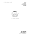
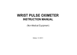
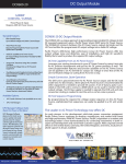
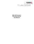
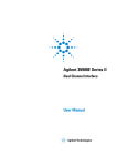
California Instruments i/iX Series II
3000–15000 VA
150–300 V
General purpose AC power sources
0–120 A
• Combination AC and DC Power Source
and Power Analyzer
• 3000 VA - 15000 VA of Output Power
• Arbitrary Waveform Generation
208
230
208
230
400
• Built-in Digital Power Analyzer
• Scope Capture Capability
• EN61000-3-2 and EN61000-3-3
• Powerful Programing Software
• Constant Power Mode
Intergrated System
The iX Series II represents a new generation of AC
and DC power source that addresses increasing
demands on test equipment to perform more
functions at a lower cost. By combining a flexible
AC/DC power source with a high performance
power analyzer, the iX Series II systems are
capable of handling complex applications that
have traditionally required multiple instruments.
The sleek integrated approach of the iX Series
II avoids the cable clutter that is commonly
found in AC test systems. The i/iX Series II is
rackmountable with a 4U chassis design. All
connections are made internally and the need for
external digital multimeters, power harmonics
analyzer and current shunts or clamps is
completely eliminated.
Using a state of the art digital signal processor in
conjunction with precision high resolution A/D
converters, the iX Series II provides more accuracy
and resolution than can be found in some
dedicated harmonic power analyzers. Since many
components in the iX Series II are shared between
the AC/DC source and the power analyzer, the
total cost of the integrated system is less than the
typical cost of a multiple unit system.
For less demanding applications, the i Series II
provides similar output and transient capabilities
as the iX Series II, as well as basic measurements.
Easy To Use Controls
Both the iX Series II and i Series II are
microprocessor controlled and can be operated
from an easy to use front panel keypad. Functions
are grouped logically and are directly accessible
from the keypad. This eliminates the need to
search through various levels of menus and/or
soft keys. A large analog control knob can be
used to quickly slew output parameters. This
858.458.0223
knob is controlled by a dynamic rate change
algorithm that combines the benefits of precise
control over small parameter changes with quick
sweeps through the entire range.
Applications
With precise output regulation and accuracy,
the iX Series II AC and DC sources address
many application areas for AC and DC power
testing. The iX also provides a high load current
capability, multi or single phase output modes,
and built-in power analyzer measurements.
Additional features including line distortion
simulation (LDS), arbitrary waveform generation,
and programmable output impedance address
requirements for product quality and regulatory
compliance testing.
Product Evaluation and Test
Increasingly, manufacturers of electronic
equipment and appliances are required to fully
evaluate and test their products over a wide
range of input line conditions. The built-in output
transient generation and readback measurement
capability offers the convenience of an easy to
use and integrated test system.
Avionics
With an output frequency range to 1000 Hz,
up to 150 VRMS, the iX Series II is well suited
for aerospace applications. Precise frequency
control and accurate load regulation are key
requirements in these applications. The standard
IEEE-488 control interface and SCPI command
language provide for easy integration into existing
ATE systems. Since the iX Series II can eliminate
the need for additional pieces of test equipment
and only occupies 7 inches of rack space (4U),
it significantly saves cost and space. Options are
available for popular avionics test routines such
as: DO-160, ABD- 0100, MIL-STD-704A-F, Boeing
7E73B-0147, and Airbus test routines.
[email protected]
AMETEK
Programmable Power
9250 Brown Deer Road
San Diego, CA 92121-2267
USA
10252013
145
i/iX Series II
Regulatory Testing
As governments are moving to enforce product
quality standards, regulatory compliance testing
is becoming a requirement for a growing
number of manufacturers. The iX Series II is
designed to meet AC source requirements for
use in Euronorm EN 61000 compliance testing.
For flicker testing, the programmable output
impedance capability of the 3001iX, 5001iX
and 15003iX can be used to create the required
IEC 725 reference impedance. Run IEC610004-11, IEC61000-4-14 and IEC61000-4-28 test
programs.
Multi-Box Configurations
For high power applications, two or three 5001i/
iX chassis can be combined to provide 10 to 15
kVA of single or three phase power. A 9003iX,
15003iX or 15003i three phase configuration can
be ordered with the MODE-iX option. This option
allows automatic switching between single or
three phase output mode. In single phase mode,
all current is available on phase A.
High Crest Factor
With a crest factor of up to 5:1, the i/iX Series II
AC source can drive difficult nonlinear loads with
ease. Since many modern products use switching
power supplies, they have a tendency to pull high
repetitive peak currents. The 5001iX can deliver
up to 110 Amps of repetitive peak current to
handle such loads.
Application Software
Windows® application software is included with
the iX and i Series II¹ . This software provides
easy access to the power source’s capabilities
without the need to develop any custom code.
The following functions are available through this
GUI program:
• Steady state output control (all parameters)
• Create, run, save, reload and print
transient programs
• Generate and save harmonic
waveforms [iX only]
• Generate and save arbitrary waveforms [iX only]
• Download data from a digital storage
oscilloscope [iX only]
• Measure and log standard measurements
• Capture and display output voltage and
current waveforms [iX only]
• Measure, display, print and log harmonic
voltage and current measurements [iX only]
• Display IEEE-488 or RS232C bus traffic to
and from the AC Source to help you develop
your own test programs..
Remote Control
Standard IEEE-488 and RS232C remote control
interfaces allow programming of all instrument
functions from an external computer. The
popular SCPI command protocol is used for
programming. Drivers for several popular
instrumentation programming environments
are available to facilitate systems integration of
the i/iX Series II. Instrument drivers for popular
programming environments such as National
Instruments LabView™ are available to speed up
system intergration.`
1. Requires PC running WindowsXP™ or Windows 2000™
146
www.ProgrammablePower.com
i/iX Series II
Harmonic Waveform Generation
Using the latest DSP technology, the iX Series
II controller is capable of generating harmonic
waveforms to test for harmonics susceptibility
of a unit under test. Included is a Graphical User
Interface program that can be used to define
harmonic waveforms by specifying amplitude and
phase for up to 50 harmonics. The waveform
data points are generated and downloaded by
the GUI to the AC source through either the USB,
IEEE-488, RS232C bus or LAN and remain in
nonvolatile memory. Up to 200 waveforms can
be stored and given a user defined name for easy
recall.
The three phase configuration iX Series II
offers independent waveform generation on
each phase allowing three phase anomalies to
be programmed. It also allows simulation of
unbalanced harmonic line conditions.
Harmonic waveform, Fund., 3rd, 5th, 7th, 9th,11th and 13th.
Two hundred user defined waveforms.
Arbitrary Waveform Generation
[iX Series II only]
Using the provided GUI program or custom
software, the user also has the ability to define
arbitrary AC waveforms. The arbitrary waveform
method of data entry provides an alternative
method of specifying AC anomalies by providing
specific waveform data points. The GUI program
includes a catalog of custom waveforms. It also
allows real-world waveforms captured on a digital
oscilloscope to be downloaded to one of the
many AC source’s waveform memories.
3000–15000 VA
iX and i Series II AC and DC Transient Generation
The iX and i Series II controllers have a powerful
AC and DC transient generation system that
allows complex sequences of voltage, frequency
and waveshapes to be generated. This further
enhances the i/iX’s capability to simulate AC line
conditions or DC disturbances. When combined
with the multi phase arbitrary waveform
capabilities, the AC and DC output possibilities
are truly exceptional. In three phase i/iX system
configurations, transient generation is controlled
independently yet time synchronized on all
three phases. Accurate phase angle control and
synchronized transient list execution provide
unparalleled accuracy in positioning AC output
events.
Transient programming is easily accomplished
from the front panel where clearly laid out menu’s
guide the user through the transient definition
process. The front panel provides a convenient
listing of the programmed transient sequence and
allows for transient execution, Start, Stop, Abort
and Resume operations.
User defined transient sequences can be saved
to nonvolatile memory for instant recall and
execution at a later time. The included Graphical
User Interface program supports transient
definitions using a spreadsheet-like data entry
grid. A library of frequently used transient
programs can be created on disk using this GUI
program.
Transient List Data Entry from the front panel
Arbitrary waveform capability is a flexible way of
simulating the effect of real-world AC power line
conditions in both engineering and production
environments.
Transient List Data Entry in GUI program.
Two hundred user defined waveforms.
858.458.0223
[email protected]
147
i/iX Series II
Measurement and Analysis
The i/iX Series II is much more than a
programmable AC and DC power source. It also
incorporates an advanced digital signal processor
based data acquisition system that continuously
monitors all AC source and load parameters.
This data acquisition system forms the basis for
all measurement and analysis functions. These
functions are accessible from the front panel and
the remote control interface.
Waveform Acquisition [iX Series II only]
The measurement system is based on real-time
digitization of the voltage and current waveforms
using a 4K deep sample buffer. This time domain
information provides detailed information on
both voltage and current waveshapes. Waveform
acquisitions can be triggered at a specific phase
angle or from a transient program to allow
precise positioning of the captured waveform
with respect to the AC source output.
The front panel LCD displays captured waveforms
with cursor readouts. The included GUI program
also allows acquired waveform data to be
displayed, printed and saved to disk.
Measurement data for single phase (iX Display).
Acquired Current waveform (iX Display).
Measurement data for all three phases (iX Display).
Harmonic Analysis [iX Series II only]
The iX Series II provides detailed amplitude and
phase information on up to 50 harmonics of
the fundamental voltage and current for either
one or three phases. Harmonic content can be
displayed in both tabular and graphical formats
on the front panel LCD for immediate feedback
to the operator. Alternatively, the included GUI
program can be used to display, print and save
harmonic measurement data. Total harmonic
distortion of both voltage and current is
calculated from the harmonic data.
Absolute amplitude bar graph display of current harmonics
with cursor positioned at the fundamental (iX Display).
Acquired Voltage waveform (iX Display).
Acquired three phase voltage waveforms display on PC.
Voltage harmonic measurement table display in absolute
values (iX Display).
148
www.ProgrammablePower.com
i/iX Series II : Product Specifications
3000–15000 VA
Operating Modes
iX Series II
AC, DC or AC+DC
i Series II
AC or DC
AC Mode Output
Frequency
Range: 16.00-1000 Hz (Note: Voltage on 300 V range derates from 300 Vrms max at 500 Hz to 150 Vrms max at 1000 Hz;
See V-F rating chart. below)
Total Power
3001i/iX: 3000 VA, 5001i/iX: 5000 VA, 9003i/iX: 3000 VA per phase, with mode iX: 9000 VA 1ø, 10001i/iX: 10000 VA, 15001i/iX:
15000 VA, 15003i/iX: 5000 VA/ø 3ø, with mode iX: 15000 VA 1ø
Load Power Factor
0 to unity at full output VA
AC Mode Voltage
Voltage Ranges
Range
V Low
V High
Load Regulation
(with ALC on):
< 0.2%
AC
0-150 V
0-300 V
Load Regulation
(with ALC off):
< 0.5% DC to 100 Hz, < 0.6% 100 Hz to 500 Hz in high voltage range,
< 2.2% 100 Hz to 500 Hz in low voltage range, < 3% 500 Hz to 1000 Hz
AC+DC
0-150 V
0-300 V
Line Regulation:
< 0.1% for 10% line change
Output Noise (20 kHz to 1 MHz)
< 250 mVrms typ., < 500 mVrms max
Harmonic Distortion (Linear)
< 1% from 16 - 66 Hz, < 2% at 400 Hz, < 3% at 800 Hz (Full resistive load)
DC Offset
< 20 mV
External Amplitude Modulation
Depth: 0 - 10 %, Frequency: DC - 2 KHz
Isolation Voltage
300 Vrms output to chassis
Voltage slew rate
200 µs for 10% to 90% of full scale change into resistive load, 0.5V / µSec
AC Mode Current
Steady State AC Current
Model
3001i/iX
5001i/iX
9003i/iX 3ø
10001i/iX
15001i/iX
15003i/iX 3ø
300 V range
11.1
18.5
11.1 /ø
37.0
55.5
18.5 /ø
150 V range
22.2
37.0
22.2 /ø
74.0
111.0
37.0 /ø
Note: Constant power mode provides increased current at reduced voltage (See chart below)
Peak Repetitive AC Current
Model
3001i/iX
5001i/iX
9003i/iX 3ø
10001i/iX
15001i/iX
15003i/iX 3ø
High range
96.0
96.0
96.0 /ø
192.0
288.0
96.0 /ø
Low range
110.0
110.0
110.0 /ø
220.0
330.0
110.0 /ø
Programming Accuracy
Voltage (rms): ± 0.2 of range, 16 to 1000 Hz, Frequency: ± 0.01 % of programmed value, Current Limit: ± 0.5 % of programmed value,
Phase: < 1.5° with balanced load at 50/60 Hz
Programming Resolution
Voltage (rms): 100 mV, Frequency: 0.01 Hz from 16 - 81.91 Hz, 0.1 Hz from 82.0 - 819.1 Hz, 1 Hz from 820-1000 Hz,
Current Limit: 0.1 A, Phase, 0.1°
Output Relay
Push-button controlled or bus controlled output relay
Output Impedance (iX Only)
Programmable Z on 3001iX, 5001iX, 9003iX and 15003iX (3ø mode only) for 50 Hz fundamental
Resistive
Range: 17 - 1000 mOhm,resolution: 4 mOhm accuracy, 2 % FS
Inductive
Range: 230 - 1000 µH, resolution: 4 µH, accuracy: 2 % FS
DC Mode Output
Power (Max at full scale of
DC Voltage Range):
3001i/iX: 2100 W, 5001i/iX: 3500 W, 9003i/iX: 2100 W/ø 3ø, 6300 W 1ø, 10001i/iX: 7000 W, 15001i/iX: 10500 W,
15003i/iX: 3500 W/ø 3ø
Voltage Ranges
Range: Low: 200 Vdc,
Line Regulation
< 0.1% FS or 10% line change
Output Noise
< 250 mV rms typ., < 500 mV rms max., (20 kHz to 1 MHz)
Max DC Current (Maximum current
at 65% of V Range)
High: 400 Vdc
Model
3001i/iX
5001i/iX
9003i/iX 3ø
10001i/iX
15001i/iX
15003i/iX 3ø
400V range
7.8
13
7.8
26
39
13
200V range
15.6
26
15.6
52
78
26
Note: Constant power mode provides increased current at reduced voltage (See chart below)
Current Limit
Programmable from 0 A to maximum current for selected range
AC+DC Mode Output
Output Power (iX only)
Full AC Power if DC component is less than 20% of full scale voltage, Full DC power if DC component is above 20%
858.458.0223
[email protected]
149
i/iX Series : Product Specifications
Measurements
Output Parameter
Current Limit Range
i Series
iX Series
Programmable 0 to 100% of range for all ranges
Programmable 0 to 100% of range for all ranges
0.1 Arms
0.1 Arms
Current Limit Resolution
Current Limit Accuracy
± 0.5 A
± 0.5 A
16.00 - 81.91 Hz (0.01 Hz resolution)
81.0 – 819.1 Hz (0.1 Hz resolution)
820 – 1000 Hz (1 Hz resolution)¹
16.00 - 81.91 Hz (0.01 Hz resolution)
81.0 – 819.1 Hz (0.1 Hz resolution)
820 – 1000 Hz (1 Hz resolution)¹
Frequency Accuracy
± 0.01% of programmed value
± 0.01% of programmed value
DC Offset Voltage
Frequency Range
Less than 20 mV with linear load.
Less than 20 mV with linear load.
Output Impedance Range
n/a
Rmin to 1000 mΩ
Lmin to 1000 μH
Output Impedance Resolution
n/a
4 mΩ
4 μH
Output Impedance Accuracy
n/a
± 2% F.S. at 796 μH and 400 mΩ
<250 mV rms (typ),
<500 mV rms (max)
<250 mV rms (typ),
<500 mV rms (max)
Output Noise (20 kHz to 1 MHz)
1 Note: AC voltage in 300V range derates from 300 Vrms max. at 500 Hz to 150 Vrms max. at 1000 Hz.
Measurements : Peak AC Current
Output Parameter
i Series
iX Series
3001i/iX
5001i/iX
110 A for 150 V range,
92 A for 300 V range
110 A for 150V range,
92 A for 300 V range,
10001i/iX
220 A for 150 V range,
184 A for 300 V range
220 A for 150 V range,
184 A for 300 V range
15001i/iX
330 A for 150 V range,
276 A for 300 V range
330 A for 150 V range,
276 A for 300 V range
Up to 5:1
Up to 5:1
Crest Factor
AC Measurements
Parameter
Range
Accuracy (±)
Resolution
Frequency
16.00 - 1000 Hz
2 counts
0.01: 16 to 81.91 Hz
0.1: 82.0 to 819.0 Hz
1: 820 to 1000 Hz
RMS Voltage
0 - 300 Volts
0.25V + 0.1%, <100 Hz
0.25V + 0.2%, 100-1000 Hz
0.01 Volt
RMS Current
0 - 40 Amps
0.25A + 0.1%, <100 Hz
0.25A + 0.2%, 100-1000 Hz
0.001 Amp
Peak Current
0 - 119 Amps
0.5A + 0.2%, <100 Hz
0.5A + 0.5%, 100-1000 Hz
0.01 Amp
VA Power
0 – 6000 VA
10 VA + 0.1%, <100 Hz
20 VA + 0.2%, 100-1000 Hz
1 VA
Real Power
0 – 6000 W
10 W + 0.1%, <100 Hz
20 W + 0.2%, 100-1000 Hz
1W
Power Factor (>0.2kVA)
0 - 1.00
0.01
Accuracy specifications apply above 100 counts. Current and Power Accuracy specifications are times two for 10001iX and times three for 15001iX. For 10001iX and 15001iX,
resolution decreases by factor of 10, ranges for current and power increases by factor of three. Measurement bandwidth is limited to 16 Khz.
DC Measurements
Parameter
Range
Accuracy (±)
Resolution
Voltage
0 – 400 Volts
0.4 Volts
0.01 Volt
Current
0 – 40 Amps
0.1 Amps
0.001 Amp
Power
0 – 6000 W
20 W
1W
Accuracy specifications apply above 100 counts. Current and Power Accuracy specifications are times two for 10001iX and times three for 15001iX. For 10001iX and 15001iX,
resolution decreases by factor of 10, ranges for current and power increases by factor of three.
150
www.ProgrammablePower.com
i/iX Series : Product Specifications
3000–15000 VA
Harmonic Measurements (iX series)
Parameter
Range
Accuracy (±)
Resolution
16.00 - 1000 Hz
2 counts
0.01 Hz to 1 Hz
32.00 Hz - 16 kHz
2° typ.
0.5°
Fundamental
0.25V
0.01V
Harmonic 2 - 50
0.25V + 0.1% + 0.1%/kHz
0.01V
Fundamental
0.05A
0.01A
Harmonic 2 - 50
0.05A + 0.1% + 0.1%/kHz
0.01A
Frequency fundamental
Frequency harmonics
Voltage
Current
Accuracy specifications are times three for three phase mode. Harmonics frequency range in three-phase mode is 32 Hz - 16 kHz. Resolution decreases by factor
of 10 for 10001iX and 15001iX.
Remote Control
IEEE-488 Interface optional / USB standard
IEEE-488 (GPIB) talker listener. Subset: AH1, C0, DC1, DT1, L3, PP0, RL2, SH1, SR1, T6, IEEE-488.2 SCPI Syntax (GPIB standard on iX)
RS232C Interface
9 pin D-shell connector, Handshake: CTS, RTS, Data bits: 7,8, Stop bits: 1, 2, Baud rate: 9600, 19200, 38400, 57600, 115200, IEEE-488.2
SCPI Syntax (Supplied with RS232C cable). (RS232C Standard on iX - LAN Optional)
(LAN Optional)
AC Input
Voltage
3001 and 9003: 208-240 ± 10% Vac, (L-N, 1ø), All other models: Standard: 208-240 ± 10% Vac, (L-L, 3ø), Option -400: 400-480 ± 10%
Vac, (L-L, 3ø) (Input range must be specified when ordering).
Input Line Current (per phase):
Model
3001i/iX
5001i/iX
9003i/iX
10001i/iX
15001i/iX
15003i/iX
187-264V
25 A
23 A
75 A
46 A
69 A
69 A
360-528V
N/A
12 A
N/A
24 A
36 A
36 A
Inrush Current per chassis
< 100 Apk for 100 µs at 208-240 V, < 50 Apk for 100 µs at 400-480 V
Line Frequency
50-60 Hz ± 10 %
Efficiency
75% typical
Power Factor
0.6 typical
Regulatory
IEC61010, EN50081-2, EN50082-2, CE EMC and Safety Mark requirements
RFI Suppression
CISPR 11, Group1 , Class A
Rear Panel Connectors
AC Input & Output terminal block with cover, IEEE-488 (GPIB) connector (rear panel), 9 pin D-Shell RS232C connector*, Remote voltage
sense terminal block, System Interface Connector, *RS232 DB9 to DB9 cable supplied
Mechanical
Dimensions
Height: 7” (178 mm), Width: 19” (483 mm), Depth: 24” (610 mm) (depth includes rear panel connectors)
Weight
per Chassis: Net: 61 lbs / 28 Kg, Shipping: 115 lbs / 52 Kg
Vibration and Shock
Designed to meet NSTA project 1A transportation levels
Air Intake/Exhaust
Forced air cooling, side air intake, rear exhaust.
Operating Humidity
0 to 95 % RAH, non condensing.
Temperature
Operating:
0 to 40° C, Storage: -20 to +85° C
Constant Power AC Mode - Available Max. AC Current
V-F Rating Chart - 300V Range
Note: Specifications are subject to change without notice. Specifications are warranted over an ambient temperature range of 25°± 5° C. Unless otherwise noted,
specifications are per phase for a sinewave with a resistive load and apply after a 30 minute warm-up period. For three phase configurations, all specifications are for L-N.
Phase angle specifications are valid under balanced load conditions only.
858.458.0223
[email protected]
151
i/iX Series : Product Specifications
Standard controller versions
Model
Output Power AC
Phase Output
Max. current per phase
Low V range
Input Voltage²
High V range
AC
DC
AC
DC
3001i/iX
3 kVA
1
22
15.6
11
7.8
208-240V
5001i/iX
5 kVA
1
37
26
18.5
13
208-240V
5001i/iX-400
5 kVA
1
37
26
18.5
13
400-480V
9003iX1
9 kVA
3
22
15.6
11
7.8
208-240V
10001i/iX¹
10 kVA
1
74
52
37
26
208-240V
10001i/iX-400¹
10 kVA
1
74
52
37
26
400-480V
10002i/iX3
10 kVA
2
37
26
18.5
13
208-240V
10 kVA
2
37
26
18.5
13
400-480V
15001i/iX1
15 kVA
1
111
78
55.5
39
208-240V
15001i/iX-4001
15 kVA
1
111
78
55.5
39
400-480V
15003i/iX
15 kVA
3
37
26
18.5
13
208-240V
15 kVA
3
37
26
18.5
13
400-480V
10002i/iX-400
3
1
15003i/iX-4001
Note (1): Supplied with System Interface cable(s). Controller in master unit only.
Note (2): All input voltage specifications are for Line to Line three phase except 3001iX and 9003iX which require single phase input only.
Note (3): For 10002iX split phase system specifications, refer to 5001iX for each phase.
Controller
Controller
i
iX
AC mode
X
X
DC mode
X
X
AC+DC mode
X
Transient programming
X
X
Arbitrary waveforms
X
Measurements (standard)
X
X
Harmonic measurements
X
Waveform acquisition
X
Programmable Impedance
X
IEEE / RS232 / USB
X
X
Storage
Non Volatile Mem. storage
16 instrument setups, 200 user defined waveforms
Waveforms
Waveform Types
i Series II: Sine, iX Series II: Sine, Square, Clipped sine, User defined
User defined waveform storage
Four groups of 50 user defined arbitrary waveforms of 1024 points for a total of 200 (One group can be active at a time)
System Interface
Inputs
Remote shutdown, External Sync, Clock/Lock (option)
Outputs
Function Strobe, Clock/Lock (option)
Protection
152
Over Load
Constant Current or Constant Voltage mode
Over Temperature
Automatic shutdown
www.ProgrammablePower.com
i/iX Series Diagram
RACK SLIDE
GENERAL DEVICES
C300S-120-B308
(OPTIONAL)
3000–15000 VA
1.18
[3.00]
16.80
[42.67]
22.56
[57.30]
.19
[.48]
1.63
[4.14]
6.97
[17.70]
4.00
[10.16]
1.48
[3.76]
19.00
[48.26]
© 2009 AMETEK Programmable Power All rights reserved. AMETEK Programmable Power is the trademark of AMETEK Inc., registered in the U.S. and other countries.
Elgar, Sorensen, California Instruments, and Power Ten are trademarks of AMETEK Inc., registered in the U.S.
858.458.0223
[email protected]
153
i/iX Series
Supplied with
User Manual, Programming Manual, Software (all on CD ROM) and RS232C serial cable.
Options
Option Code
Description
-LKM
Clock/Lock Master
-LKS
Clock/Lock Auxiliary
-LNS
Internal AC Line Sync.
-FC
Modifies output frequency control to ± 0.15%
-XLS
External AC Line Sync adaptor. (-LNS and XLS are mutually exclusive)
-MODE-iX
Switches between 1 and 3 phase output modes, for 9003iX or 15003i/iX only. (Separate box)
OMNI-1-18i
Impedance matching network for single phase 3001i/iX or 5001i/iX to support IEC-1000-3-3 flicker tests.
OMNI-3-18i
Impedance matching network for three phase 9003iX or 15003i/iX systems to support IEC-1000-3-3 flicker tests.
OMNI-3-37i
Impedance matching network for three phase 30003i/iX systems to support IEC-1000-3-3 flicker tests.
-RMS
Rackmount Slides.
-WHM
Watt-Hour Measurement option.
-400
400-480 Volt Line to Line AC input.
-FC
Modifies output frequency control to ± 0.15%
-411
IEC61000-4-11 test firmware. See also EOS1/3.
-413
IEC61000-4-13 Harmonics and Interharmonics test firmware and hardware.
-EOS-1
IEC61000-4-11 Electronic Output Switch (1 phase) Includes -411 option. Refer to EOS data sheet for details.
-EOS-3
IEC61000-4-11 Electronic Output Switch (3 phase) Includes -411 option. Refer to EOS data sheet for details.
-LAN
LXI Ethernet LAN Interface (Rj45 Connector) (iX Only)
Cabinets
Multi box iX Series II systems can be factory installed and wired in 19 inch cabinets. Cabinet configurations can be ordered by
preceeding the model number with a “C1-C4” prefix. Contact factory for pricing and details.
Avionics Test Routine Options
-ABD
Airbus Directive 0100.1.8 tests.
-AMD
Airbus AMD24 tests.
-A350
Airbus A350 tests.
-AIRB
Airbus test package (A380, A350, AMD24)
-B787
Boeing 787B3-0147 tests.
-160
RTCA/DO-160D and EUROCAE test firmware. Refer to -160 option data sheet for details.
* Note Reference the Avionics Test User Manual P/N 4994-971 for a complete listing of performance capabilities.
154
www.ProgrammablePower.com