1
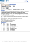
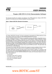
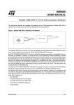
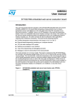
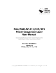
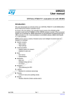
UM0230
User manual
Short-range RFID reader
with autonomous functions
This User manual describes the hardware and software of the demokit for the
STMicroelectronics short-range RFID reader with Autonomous functions. The demokit runs
under the Windows 98, Windows 2000 and Windows XP operating systems.
The purpose of this demokit is to demonstrate the key features of the STMicroelectronics
Short Range RFID family. All products in the family meet global security and cost
requirements by complying with the worldwide ISO 14443-B standard and free licensing
policy. This particular demokit can be powered in several ways, has a USB and an RS232
interface, and offers PC and autonomous operating modes.
Owing to this diversity and flexibility, it is easier for the customer to further develop the
system according to his needs. All the design source data are delivered with the kit, ready to
be reused in further developments. The target applications for this demokit are data
collection, access control, medical, traceability, brand protection, e-purse and vending
machines.
Figure 1.
April 2006
Demokit hardware for a short-range RFID reader with autonomous
functions
Rev 1
1/19
www.st.com
Contents
UM0230 - User manual
Contents
1
2
3
Demokit overview . . . . . . . . . . . . . . . . . . . . . . . . . . . . . . . . . . . . . . . . . . . 5
1.1
RFID Short Range products . . . . . . . . . . . . . . . . . . . . . . . . . . . . . . . . . . . . 5
1.2
µPSD3422EV Turbo Plus Series product . . . . . . . . . . . . . . . . . . . . . . . . . . 5
1.3
M41T65 (RTC) Serial Real-Time Clock product . . . . . . . . . . . . . . . . . . . . . 5
Getting started . . . . . . . . . . . . . . . . . . . . . . . . . . . . . . . . . . . . . . . . . . . . . . 7
2.1
Software installation . . . . . . . . . . . . . . . . . . . . . . . . . . . . . . . . . . . . . . . . . . 7
2.2
Physical connections . . . . . . . . . . . . . . . . . . . . . . . . . . . . . . . . . . . . . . . . . 9
2.3
Launching the short-range RFID reader dashboard software . . . . . . . . . 10
Short-range reader . . . . . . . . . . . . . . . . . . . . . . . . . . . . . . . . . . . . . . . . . 11
3.1
Memory records . . . . . . . . . . . . . . . . . . . . . . . . . . . . . . . . . . . . . . . . . . . . 12
3.2
Control board description . . . . . . . . . . . . . . . . . . . . . . . . . . . . . . . . . . . . . 12
4
Win32 Dashboard Control . . . . . . . . . . . . . . . . . . . . . . . . . . . . . . . . . . . 14
5
HyperTerminal Control . . . . . . . . . . . . . . . . . . . . . . . . . . . . . . . . . . . . . . 15
Appendix A Schematic diagrams . . . . . . . . . . . . . . . . . . . . . . . . . . . . . . . . . . . . . 16
6
References . . . . . . . . . . . . . . . . . . . . . . . . . . . . . . . . . . . . . . . . . . . . . . . . 18
7
Revision history . . . . . . . . . . . . . . . . . . . . . . . . . . . . . . . . . . . . . . . . . . . 18
2/19
UM0230 - User manual
List of tables
List of tables
Table 1.
Table 2.
Table 3.
Table 4.
Table 5.
Event record structure . . . . . . . . . . . . . . . . . . . . . . . . . . . . . . . . . . . . . . . . . . . . . . . . . . . . 12
Status Byte . . . . . . . . . . . . . . . . . . . . . . . . . . . . . . . . . . . . . . . . . . . . . . . . . . . . . . . . . . . . . 12
Onboard LED description . . . . . . . . . . . . . . . . . . . . . . . . . . . . . . . . . . . . . . . . . . . . . . . . . . 12
RS232 interface commands . . . . . . . . . . . . . . . . . . . . . . . . . . . . . . . . . . . . . . . . . . . . . . . . 15
Document revision history . . . . . . . . . . . . . . . . . . . . . . . . . . . . . . . . . . . . . . . . . . . . . . . . . 18
3/19
List of figures
UM0230 - User manual
List of figures
Figure 1.
Figure 2.
Figure 3.
Figure 4.
Figure 5.
Figure 6.
Figure 7.
Figure 8.
Figure 9.
Figure 10.
Figure 11.
4/19
Demokit hardware for a short-range RFID reader with autonomous functions . . . . . . . . . . 1
Welcome window . . . . . . . . . . . . . . . . . . . . . . . . . . . . . . . . . . . . . . . . . . . . . . . . . . . . . . . . . 7
Choose Destination Location window . . . . . . . . . . . . . . . . . . . . . . . . . . . . . . . . . . . . . . . . . . 8
Connecting the Short-Range RFID reader . . . . . . . . . . . . . . . . . . . . . . . . . . . . . . . . . . . . . . 9
Dashboard Main Window . . . . . . . . . . . . . . . . . . . . . . . . . . . . . . . . . . . . . . . . . . . . . . . . . . 10
HyperTerminal . . . . . . . . . . . . . . . . . . . . . . . . . . . . . . . . . . . . . . . . . . . . . . . . . . . . . . . . . . 10
HyperTerminal settings . . . . . . . . . . . . . . . . . . . . . . . . . . . . . . . . . . . . . . . . . . . . . . . . . . . . 10
Control board description . . . . . . . . . . . . . . . . . . . . . . . . . . . . . . . . . . . . . . . . . . . . . . . . . . 13
Description of the main Dashboard window . . . . . . . . . . . . . . . . . . . . . . . . . . . . . . . . . . . . 14
Control board schematics . . . . . . . . . . . . . . . . . . . . . . . . . . . . . . . . . . . . . . . . . . . . . . . . . . 16
Antenna board schematics . . . . . . . . . . . . . . . . . . . . . . . . . . . . . . . . . . . . . . . . . . . . . . . . . 17
UM0230 - User manual
1
Demokit overview
Demokit overview
The demokit tools for short-range RFID readers with Autonomous functions are designed to
demonstrate several STMicroelectronics products (see Section 6: References):
RFID Short Range, Turbo Plus Series and Serial Real-Time Clock products.
1.1
RFID Short Range products
These STMicroelectronics products include the CRX14 and CR14 readers, and several
contactless memories/tag products: SRI4K, SRIX4K, SRIX512.
All the contactless memories are powered by a transmitted carrier radio wave at 13.56MHz
and are compliant with the ISO 14443-B recommendation for the transfer of power and
signals via radio transmission. The Short Range CRX14 / CR14 RFID reader circuitry
amplitude modulates (10% modulation) the data on the carrier using amplitude shift keying
(ASK) and the tag replies by load modulating the data on the carrier using the BPSK (Bit
Phase Shift Keying) of a 847kHz subcarrier. The data transfer rate in each direction is 106
Kbit/second.
1.2
µPSD3422EV Turbo Plus Series product
The µPSD3422EV belongs to the popular µPSD family of 8051-class embedded Flash
microcontrollers that offers system-level-integration with world-leading Flash memory and
SRAM densities (up to 256-KBytes and 32-KBytes, respectively) for general-purpose 8-bit
embedded applications.
The µPSD3422EV Turbo Plus series performs up to 10 MIPS peak and provides full-speed
USB. A JTAG interface supports in-system programming and MCU core debug with highspeed instruction tracing capability, eliminating the need for a hardware In-Circuit Emulator
(ICE). Other peripherals include a 16-bit Programmable Counter Array (PCA), an 8-channel,
10-bit resolution analog-to-digital converter, SPI and IrDA interfaces, six PWM (pulse-width
modulated) channels, an I²C (Intelligent Interface Controller) master/slave bus controller,
two standard UARTs (Universal Asynchronous Receiver/Transmitter), supervisory functions
such as a watchdog timer and low-voltage detect, and up to 45 general-purpose I/O pins.
1.3
M41T65 (RTC) Serial Real-Time Clock product
The M41T65 (RTC) is used in a broad range of applications. It is available in a lead-free 16pin QFN package (just 3mm²) and is designed for a bus operating voltage from 3.6V down to
1.3V, but will maintain timekeeping at supply levels as low as 1.0V, thus providing more
robust system performance. Operating current is only 350µA on a 3.0V supply, making the
RTCs ideal for battery operation and handheld applications. M41T65 operates over the
industrial temperature range of –40 to +85° C.
5/19
Demokit overview
UM0230 - User manual
The kit consists of:
●
Circuit boards – Control board with µPSD3422EV and Boosted antenna board
●
USB cable
●
I2C cable
●
Some transponder samples (of the SRIX4K)
●
CD with control software, related user manual, application notes and datasheets.
Application features:
6/19
●
RAM: 32 Mbit
●
HDD free space: 5MB
●
USB version 1.1
●
Runs on the Windows 98 SE Platform, Windows 2000, Windows XP
UM0230 - User manual
Getting started
2
Getting started
2.1
Software installation
●
First insert the CD supplied by STMicroelectronics in your CD drive.
●
The auto run will bring up the CD content. Install the Win32 Dashboard software from
the Reader software section.
●
After opening the folder, run the setup.exe program.
●
Read the text of the Welcome window (Figure 2), and then click on “Next”.
Figure 2.
Welcome window
7/19
Getting started
●
UM0230 - User manual
Choose your destination location as shown in Figure 3, then click on “Next”. The default
folder is C:\Program Files\STMicroelectronics\RFID_DashBoard
Figure 3.
8/19
Choose Destination Location window
UM0230 - User manual
2.2
Getting started
Physical connections
The short-range RFID reader can be connected in different ways as shown in Figure 4. To
proceed to the connection do as follows:
Caution:
●
Connect the boosted Antenna board to the Control board using the supplied 4-wire
ribbon cable.
●
Connect the Control board to your PC/Laptop using the supplied USB cable and let
Windows recognize the HID class device (no user action needed).
Optionally you can connect the Control board to your PC/Laptop using the RS232
interface.
●
In case you plan to use some of the autonomous functions you can connect a 9V
battery or an external DC power supply (6V to 12V).
Disconnect the battery when it is not being used!
Figure 4.
Connecting the Short-Range RFID reader
Antenna
Board
RS232
USB
Control
Board
I²C
6V-12V
9V battery
DC
power supply
–
+
ai12808
9/19
Getting started
2.3
UM0230 - User manual
Launching the short-range RFID reader dashboard software
In the Start menu, click on Programs and select Reader’s Win32 Dashboard to launch the
dashboard software. The Dashboard Main Window shown in Figure 5 appears.
Figure 5.
Dashboard Main Window
It is also possible to partially control the demokit via UART. To do so, start Windows
HyperTerminal (Figure 6) and set up the port settings according to the screenshot shown on
the right-hand-side figure (Figure 7). The UART communication speed is of 9600kbs, 8 data
bits with no parity and 1 stop bit.
Figure 6.
10/19
HyperTerminal
Figure 7.
HyperTerminal settings
UM0230 - User manual
3
Short-range reader
Short-range reader
The reader has two main modes of operation:
●
CRX14USB Demokit Mode
●
Autonomous Mode
In the CRX14USB Demokit Mode, the reader behaves exactly in the same way as in the
CRX14USB Demokit (see the UM0080 User manual) and is fully compatible with the
CRX14Demokit software.
In the Autonomous Mode, the PC can send a macro-command to the reader via the USB or
the RS232 cable, and the reader can then execute it without any further need of the PC.
There are two Autonomous Mode sub-functions: AutoRead and AutoWrite.
●
In the AutoRead cycle: after a “Start” (from either the push button or the PC), the
onboard reader reads the UID of whatever tag (STMicroelectronics Short Range family)
comes into the antenna field, and deals with the ASCII User Data (either read
(AutoRead) or write operations (AutoWrite)). Every event is logged as a record in the
Flash memory of the µPSD.
●
In the AutoWrite cycle: first the reader has to memorize the user phrase, then, after a
“Start” (from the push button or the PC), the reader always writes the same ASCII
phrase to the User Data area of whatever tag (STMicroelectronics Short Range family)
that comes into the antenna field. The rest of the User Data is filled with blanks.
Successful read and write operations are indicated by the flashing of Green LED 1. The
cycles have to be ended by a “Stop” (from either the push button or the PC). The only case
where a cycle will end automatically is when the Flash memory space is full (full FLASH
detected). Once the operation is stopped, the stored data can be downloaded to the PC
through a USB or UART macro-command. If the Autonomous reader cycle is stopped the
whole Flash memory record storage space can be erased via another macro-command.
Switching between the CRX14USB Demokit Mode and the Autonomous Mode can be done
either through a software command from the PC or by pressing and holding the onboard
button (SW1) for a few seconds.
11/19
Short-range reader
3.1
UM0230 - User manual
Memory records
Autonomous Events are all being stored in the Flash memory space of the onboard
microcontroller. To minimize and simplify Flash memory management, a simple principle of
incremental write of records with fixed length (32 Bytes) is used. The structure of an event
record is described in Table 1.
Table 1.
Event record structure
Name
Offset [Bytes] Length [Bytes]
Header
0
1
Header of the record
Status Byte
1
1
Status byte of the reader
Data Field
2
16
Storage of the User Data received in Auto
Read Mode
UID
18
8
Unique identifier of the tag that triggered
Autonomous Event
Date Time
26
6
Time Stamp of the Autonomous Event
Table 2.
Status Byte
Name
Bit order
Description
Reader Mode
0
Autonomous / CRX14 Demokit mode (0 / 1)
Autonomous Cycle
1
Run / Stop (0 / 1)
Autonomous Status
2
AutoWrite / AutoRead (0 / 1)
Record Type
3
State change notice / Data Record (0 / 1)
System Notice
4
Power lost / Default (0 / 1)
RFU
3.2
Description
5-7
Reserved
Control board description
To use the Control board in Autonomous mode it is useful to get familiar with the onboard
diagnostic LEDs:
●
Green LED 1 (the green LED closer to the µPSD chip) lights up to indicate an activity
on the interface to the higher system, that is on the USB or RS232 ports.
●
The red LED shows communication activity on the I²C bus and can therefore be
interpreted simply as RF activity.
●
Green LED 2 informs about the operating status of the board. It will light up in a
continuous way in the CXR14USB Demokit mode and flash in the Autonomous mode.
Table 3.
Onboard LED description
Onboard LED
12/19
Description
Green LED 1
Activity on PC interfaces (USB / RS232)
Red LED
Activity on I2C interface (delegated to RF activity)
Green LED 2
Reader’s mode of operation
Continuous / Flashing = CRX14USB Demokit mode / Autonomous mode
UM0230 - User manual
Figure 8.
Short-range reader
Control board description
µPSD
USB
LEDs
Ext.
JTAG
I²C
RS232
DC
power
PS2
(optional)
Button
1. Ext. means Extension header. The extension header is optional.
13/19
Win32 Dashboard Control
4
UM0230 - User manual
Win32 Dashboard Control
The dashboard of the short-range RFID reader is divided into five panels: “Mode Switch”,
“Mode Control”, “RTC Control”, “Memory Records” and “Runtime Log”. They are shown in
Figure 9.
In the “Mode Switch” panel, located at the center of the window, the user can switch modes
(Switch Mode button) or check (Get Mode button) the current operating mode of the reader.
The “Mode Control” panel, on the left-hand side of the window, contains controls for
Autonomous cycle setup and supervision: Auto Read Mode button, Auto Write Mode button,
AutoWrite Mode Phrase edit box and Start / Stop button.
The panel also accommodates the Download All and Erase All buttons used for the
maintenance of the Event Records stored in the onboard memory.
The three software LEDs that mirror the real-time behavior of the reader are also on the
“Mode Control” panel.
The “RTC Control” panel, located below the “Mode Switch” panel, contains the controls
related to the reader’s Real Time Clock (RTC) chip: Set Time and Get Time buttons.
By pressing the Sync w PC button the user can easily synchronize the onboard reader’s
time with the local PC/Laptop time.
The “Memory Records” panel, located at the bottom of the window, stores the information
received from the reader after the Download All button has been pressed.
The “Runtime Log” panel, on the right-hand side of the window, simply traces all the activity
managed by the Win32 Dashboard.
Figure 9.
Description of the main Dashboard window
Mode Control
14/19
Mode Switch
RTC Control
Memory Records
Runtime Log
UM0230 - User manual
5
HyperTerminal Control
HyperTerminal Control
The short-range reader can also be operated using an RS232 terminal software. A basic list
of the commands used for that purpose is provided in Table 4. The response to these
commands is usually formatted as a human readable string to be easily displayed on a
win32 terminal.
Table 4.
RS232 interface commands
Name
Command
Response/Description
Get Mode
‘m’
Current Status Byte (Hexadecimal)
Switch Mode
‘s’
Status Byte after the change (Hexadecimal)
Get Time
‘t’
Board time from RTC
Start/Stop
‘r’
Status Byte after the change (Hexadecimal)
Download All
‘d’
Memory record dump
Erase Flash
‘e’
Confirmation of operation
Help
‘?’
List of available commands
15/19
JP1
2
1
2
3
4
R3
100k
+5V
DD+
GND
C10
4n7
plus
Shottky
D3
plus
R2
1k
R1
6k8
VUSB
R5
R4
PC7
V3.3
VPSD
C13
100n
C15
100n
1
1
V5.0
V3.3
2
2
P3.6
JP8
JP7
SDA
R13
4k7
P3.7
C16
100n
I2C Interface
C14
100n
V3.3
SCL
R14
4k7
C17
100n
V5.0
GND
RSTn
R9
100k
Supply decoupling
R12
0
R8
0
V5.0
CON4
J2
4
3
2
1
C18
100n
VPSD
22
22
V5.0
SDA
GND
SCL
C1
47u / 16V
PSD Voltage selector + Reset
USB1X90B
JP2
D1
Shottky
USB connector
VUSB
9V BATT
1
CP1 SDC-16
1
2
3
S1
S1
S2
S2
OUT
CON4
J3
GND
GND
USBR+
USBR-
4
3
2
1
KF52/DPAK
IN
VUSB
1
U1
V5.0
SDA
GND
SCL
CON4
J4
D2
4
3
2
1
V5.0
SDA
GND
SCL
Shottky
D4
Shottky
C2
10u / 6.3V
GND
3
U2
LE33
Vin Vout
GNDGND
GNDGND
INH NC
1
2
3
4
C6
10u / 6.3V
V3.3
V3.3
USBR+
VPSD
GND
USBRPC2
TCK
TMS
PD1
PC7
TDO
TDI
1
2
3
4
5
6
7
8
9
10
11
12
13
U5
Turbo uPSD Plus
8
7
6
5
PD1/CLKIN
PC7
PC6/TDO
PC5/TDI
DEBUG
3.3V Vcc
USB+/R+
Vdd (PSD)
GND
USBPC2/Vstby
PC1/TCK
PC0/TMS
X2
GND
XTAL 32768Hz
1
2
3
4
U6
XI
XO
Vss
WDO
12
11
10
9
M41T65
nc
I/F/O
SCL
SDA
V3.3
P3.2
SCL
SDA
39
38
37
36
35
34
33
32
31
30
29
28
27
100n
C4
X1
XTAL 24MHz
P3.7
P3.6
P3.5
P3.4
Ai5
Ai4
Ai3
Ai2
Ai1
Ai0
VPSD
C7
100n
100n
C5
C12 22p
C11 22p
C8
100n
HOLE4
HOLE1
1
1
HOLE3
HOLE2
Ai7
PB7
PB6
V5.0
GND
1
3
5
7
9
2
4
6
8
10
CON10AP
J5
Ai6
Ai5
Ai4
V3.3
GND
EXD I/F - optional
1
1
Mounting Holes
P1.5/SR/Ai5
P1.4/SC/Ai4
P1.3/TXD1(IrDA)/Ai3
P1.2/RXD1(IrDA)/Ai2
P1.1/T2X/Ai1
uPSD34xxT
P1.0/T2/Ai0
Vdd (PSD)
XTAL2
XTAL1
P3.7/SCL
P3.6/SDA
P3.5/C1
P3.4/C0
RTC (Real-Time Clock)
C3
1u / 6.3V
V5.0
RS232 Interface
V3.3
P4.3
Rx
16
1
3
4
5
2
6
10
11
13
8
14
7
12
9
Tx
P4.2
Tx
Rx
GND
RJTG1 RJTG2 RJTG3 RJTG4
10k
10k
10k
10k
V3.3
JTAG connection
T1OUT
T2OUT
R1OUT
R2OUT
P1
4
3
P3.2 2 SW 1
1
P4.7
P4.6
P4.5
P3.2
470
R10
470
R7
470
R6
10k
R11
GREEN LED
D7
RED LED
D6
GREEN LED
D5
V5.0
Date:
Size
A3
Title
6-pin Mini-DIN (PS/2):
1 - Data
2 - Not Implemented
3 - Ground
4 - Vcc (+5V)
5 - Clock
6 - Not Implemented
M-DIN_6-R
J6
P3.3
5
3
1
+
+
+
+
+
+
+
GND
R15
4k7
Sheet
P3.4
R16
4k7
V5.0
2
4
6
8
10 GND
12 GND
14
CON14AP
+
+
+
+
+
+
+
J1
4p-JTAG
W ednesday March 08 2006
Document Number
1.1
SHAKY: RFID Reader
6
4
2
V5.0
V3.3
V3.3
V3.3
V3.3
CONNECTOR DB9
1
GND 3
TDI 5
V3.3 7
TMS 9
TCK 11
TDO 13
LED Indicators + button
5
9
4
8
3
7
2
6
1
PS2 Interface - optional
ST3232E
VCC
C1+
C1C2+
C2V+
V-
T2IN
T1IN
R1IN
R2IN
U3
TCK
6.0V - 15V
GND
TMS
Power management
16
15
14
13
nc
nc
Vcc
nc
Vss
nc
nc
nc
V3.3
PB0
PB1
PB2
PB3
PB4
V3.3
PB5
GND
RSTn
PB6
PB7
Ai7
Ai6
52
51
50
49
48
47
46
45
44
43
42
41
40
PB0
PB1
PB2
PB3
PB4
Vcc/Vref
PB5
GND
RESET
PB6
PB7
P1.7/SS/Ai7
P1.6/ST/Ai6
P4.7/PCACLK1/SPISEL
P4.6/TCM5/SPITXD
P4.5/TCM4/SPIRXD
P4.4/TCM3/SPICLK
P4.3/TXD1(IrDA)/PCACLK0
GND
P4.2/TCM2/RXD1(IrDA)
P4.1/TCM1/T2X
P4.0/TCM0/T2
P3.0/RXD0
P3.1/TXD0
P3.2/TG0/EXINT0
P3.3/TG1/EXINT1
14
15
16
17
18
19
20
21
22
23
24
25
26
P4.7
P4.6
P4.5
P4.4
P4.3
GND
P4.2
P4.1
P4.0
P3.0
P3.1
P3.2
P3.3
TDI
16/19
TDO
1
Appendix A
5
6
7
8
Schematic diagrams
UM0230 - User manual
Schematic diagrams
Figure 10. Control board schematics
22nF50V
C43
FL1
RFIN
1
2
3
4
5
6
7
8
CRX14
Vref
Vcc
RF IN RF OUT
E0
GND_RF
E1
OSC1
E2
OSC2
GND_RF GND
GND
SCL
GND
SDA
U1
VCC
16
15
14
13
12
11
10
9
J2
FL2
FL3
FL4
FL5
22u
C29
C10 100n
22u
R6
22K
R3
15K
100n
C11
L3
10uH
C21 VCC
To RFIN
1
2
3
4
7pF
X2
13.56MHz
C45
C44 7pF
180p
C5
330p
C46
C1
18p
22u
100n
C30
C7
C36
36p
R10
47
22u
C25
R2
8.2K
R16
68
R13
10K
l9
22uH
vcc
D2
1N4148
C47
100p
L10
22uH
From Ant
Q2
BCP5616
27p
C3
10p
C40
150p
C39
1uH
L11
0.15uH
L12
68p
C42
C41
C48
0
R9
C49
100p
3.3
option
R8
R7
ANT
UM0230 - User manual
Schematic diagrams
Figure 11. Antenna board schematics
ai12824
17/19
References
6
7
UM0230 - User manual
References
●
User manual UM0080: “Reader USB CRX14 (V4.0) Demonstration Software”.
●
CR14 datasheet: “Low Cost ISO14443 type-B Contactless Coupler Chip with AntiCollision and CRC Management”
●
CRX14 datasheet: “Low Cost ISO14443 type-B Contactless Coupler Chip with AntiCollision, CRC Management and Anti-Clone Function”
●
µPSD3422EV datasheet: “Turbo Plus Series, Fast Turbo 8032 MCU with USB and
Programmable Logic”
●
M41T65 datasheet: “Serial Access Real-Time Clock with Alarms”
Revision history
Table 5.
18/19
Document revision history
Date
Revision
14-Apr-2006
1
Changes
Initial release.
UM0230 - User manual
Please Read Carefully:
Information in this document is provided solely in connection with ST products. STMicroelectronics NV and its subsidiaries (“ST”) reserve the
right to make changes, corrections, modifications or improvements, to this document, and the products and services described herein at any
time, without notice.
All ST products are sold pursuant to ST’s terms and conditions of sale.
Purchasers are solely responsible for the choice, selection and use of the ST products and services described herein, and ST assumes no
liability whatsoever relating to the choice, selection or use of the ST products and services described herein.
No license, express or implied, by estoppel or otherwise, to any intellectual property rights is granted under this document. If any part of this
document refers to any third party products or services it shall not be deemed a license grant by ST for the use of such third party products
or services, or any intellectual property contained therein or considered as a warranty covering the use in any manner whatsoever of such
third party products or services or any intellectual property contained therein.
UNLESS OTHERWISE SET FORTH IN ST’S TERMS AND CONDITIONS OF SALE ST DISCLAIMS ANY EXPRESS OR IMPLIED
WARRANTY WITH RESPECT TO THE USE AND/OR SALE OF ST PRODUCTS INCLUDING WITHOUT LIMITATION IMPLIED
WARRANTIES OF MERCHANTABILITY, FITNESS FOR A PARTICULAR PURPOSE (AND THEIR EQUIVALENTS UNDER THE LAWS
OF ANY JURISDICTION), OR INFRINGEMENT OF ANY PATENT, COPYRIGHT OR OTHER INTELLECTUAL PROPERTY RIGHT.
UNLESS EXPRESSLY APPROVED IN WRITING BY AN AUTHORIZE REPRESENTATIVE OF ST, ST PRODUCTS ARE NOT DESIGNED,
AUTHORIZED OR WARRANTED FOR USE IN MILITARY, AIR CRAFT, SPACE, LIFE SAVING, OR LIFE SUSTAINING APPLICATIONS,
NOR IN PRODUCTS OR SYSTEMS, WHERE FAILURE OR MALFUNCTION MAY RESULT IN PERSONAL INJURY, DEATH, OR
SEVERE PROPERTY OR ENVIRONMENTAL DAMAGE.
Resale of ST products with provisions different from the statements and/or technical features set forth in this document shall immediately void
any warranty granted by ST for the ST product or service described herein and shall not create or extend in any manner whatsoever, any
liability of ST.
ST and the ST logo are trademarks or registered trademarks of ST in various countries.
Information in this document supersedes and replaces all information previously supplied.
The ST logo is a registered trademark of STMicroelectronics. All other names are the property of their respective owners.
© 2006 STMicroelectronics - All rights reserved
STMicroelectronics group of companies
Australia - Belgium - Brazil - Canada - China - Czech Republic - Finland - France - Germany - Hong Kong - India - Israel - Italy - Japan Malaysia - Malta - Morocco - Singapore - Spain - Sweden - Switzerland - United Kingdom - United States of America
www.st.com
19/19