1
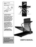
Model No. NTEL05900
Serial No.
USER'S MANUAL
Serial
Number
Decal
QUESTIONS?
As a manufacturer, we are committed to providing complete
customer satisfaction. If you
have questions, or if there are
missing parts, we will guarantee
complete satisfaction through
direct assistance from our factory.
TO AVOID UNNECESSARY
DELAYS, PLEASE CALL DIRECT
TO OUR TOLL-FREE CUSTOMER
HOT LINE. The trained technicians on our customer hot line
will provide immediate assistance, free of charge to you.
CUSTOMER
HOT LINE:
1-888-825-2588
Mon.-Fri.,
6 a.m.-6 p.m. MST
A CAUTION
Read all precautions and instructions in this manual before using
this equipment. Keep this manual
for future reference.
e at
www.nordictrack.com
new products,
prizes,
fitness tips, and much more!
®
TABLE OF CONTENTS
IMPORTANT PRECAUTIONS
.............................................................
BEFORE YOU BEGIN ...................................................................
ASSEMBLY ...........................................................................
HOW TO USE THE ELLIPTICAL CROSSTRAINER
.............................................
MAINTENANCE AND TROUBLESHOOTING
.................................................
CONDITIONING GUIDELINES ............................................................
PART LIST ...........................................................................
EXPLODED DRAWING .................................................................
HOW TO ORDER REPLACEMENT PARTS ...........................................
LIMITED WARRANTY
...........................................................
NordicTrack '_is a registered trademark of ICON Health & Fitness, Inc.
2
3
4
5
9
11
12
14
15
Back Cover
Back Cover
IMPORTANT PRECAUTIONS
WARNING:
To reduce the risk of serious injury, read the following
important precau-
tions before using the elliptical crosstrainer.
1. Read all instructions in this manual before
using the elliptical crosstrainer. Always wear
athletic shoes for foot protection.
using the elli ptical crosstrainer.
2. It is the responsibility of the owner to ensure
that all users of the elliptical crosstrainer
are adequately informed of all precautions .......
9. Always hold the handlebar or the upper
body arms when mounting, dismounting,
the elliptical crosstrainer.
3. The elliptical crosstrainer is intended for
in-home use only, Do not use the elliptical
crosstrainer in any commercial, rental, or
institutional setting.
10. Keep your back straight when using the elliptical crosstrainer. Do not arch your back.
or
11. If you feel pain or dizziness at any time
while exercising, stop immediately and
begin cooling down.
4. Place the elliptical crosstrainer on a level
surface, with a mat beneath it to protect the
floor or carpet. Keep the elliptical crosstrainer indoors, away from moisture and dust.
12. The pulse sensor is not a medical device.
Various factors, including the user's movement, may affect the accuracy of heart rate
readings. The pulse sensor is intended only
as an exercise aid in determining heart rate
trends in general.
5. Inspect and tighten all parts regularly.
Replace any worn parts immediately.
6. Keep children under age 12 and pets away
from the elliptical crosstrainer at all times.
13. When you stop exercising, allow the pedals
to slowly come to a complete stop. The elliptical crosstrainer does not have a free
wheel; the pedals will continue to move until
the flywheel stops.
7. The elliptical crosstrainer should not be used
by persons weighing more than 250 pounds,
8. Wear appropriate exercise clothing when
WARNING:
Before beginning this or any exercise program, consult your physician.
This is especially important for persons over the age of 35 or persons with pre-existing health problems. Read all instructions before using. ICON assumes no responsibility for personal injury or
property damage sustained by or through the use of this product.
3
BEFORE YOU BEGIN
Congratulations for selecting the new NordicTrack <_
VGR910 elliptical crosstrainer. The NordicTrack '_
VGR910 is an incredibly smooth exerciser that moves
your feet in a natural elliptical path, minimizing the
impact on your knees and ankles. And the unique
NordicTrack ®VGR910 features adjustable resistance
and incline to help you get the most from your exercise.
Welcome to a whole new world of natural, ellipticalmotion exercise from NordicTrack.
tional questions, please call our Customer Service
Department toll-free at 1-888-825-2588, Monday
through Friday, 6 a.m. until 6 p.m. Mountain Time
(excluding holidays). To help us assist you, please
note the product model number and serial number
before calling. The model number is NTEL05900. The
serial number can be found on a decal attached to the
elliptical crosstrainer (see the front cover of this manual for the location of the decal).
For your benefit, read this manual carefully before
you use the NordicTrack_'VGR910. If you have addi-
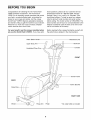
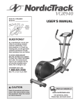
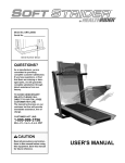
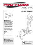
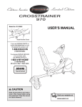
Before reading further, please familiarize yourself with
the parts that are labeled in the drawing below.
Water Bottle Holder _
Resistance Dial
Bookrack
Upper Body Arm
Handlebar/Pulse
Console
Gril
FRONT
Incline Frame
BACK
Incline Bracket
Pedal
RIGHT SIDE
Wheel
Pedal Arm
Pedal
4
*No water bottle is included
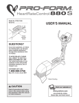
ASSEMBLY
Assembly requires two people. Place all parts of the elliptical crosstrainer in a cleared area and remove the
packing materials. Do not dispose of the packing materials until assembly is completed. In addition to the two
included allen wrenches, assembly requires a phillips screwdriver
_
_,
an adjustable
wrench _,
a rubber mallet t.....
.....
' _1
, and pliers __
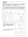
As you assemble the elliptical crosstrainer use the drawings below to identify the small parts used in assembly.
The number in parenthesis below each drawing refers to the key number of the part, from the PART LIST on
page 14. The second number refers to the quantity used in assembly. Note: Some small parts may have been
pre-attached for shipping. If a part is not in the parts bag, check to see if it has been pre-assembled.
.
ir
j j
\
/\
.....
M10 Nylon Locknut (26)-7
/'
,,,,ii_!i7
i
j
_
,
i
_
ii
f
t
,,
i
_z
, i i ii
M8 Washer (33)-2
Chrome Tube
Washer (84)-2
Y
",',,"",",,',,",',,"t,,",',,"t',,",L,,i",i,,",",,,,","'",,,',,
MI0 x 85mm Bolt (25)-1
, S L;,_,_,'> PgS,_,_,
Plastic Pedal
Spacer (92)-2
Pedal Screw (43)-6
<:J
Incline Axle Screw
(30)-2
26
94
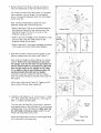
1. Identify the Rear Stabilizer (94), which has Wheels (45)
attached to it.
Attach the Rear Stabilizer (94) to the rear of the Frame
(1) with the two Rear Stabilizer Bolts (60) and two M1O
Nylon Locknuts (26). Make sure that the Rear
Stabilizer is turned so the Wheels are not touching
the floor.
2. Attach the Front Stabilizer (90) to the front of the
Frame (1) with the two Front Stabilizer Bolts (86) and
two M10 Nylon Locknuts (26).
2
90
86
26
jl
26
5
i
J
i ",)
i J
M8 Split
VVasher (58)-2
_
3. Slide an M8 Split Washer (58) and an M8 Washer (33)
onto an Incline Axle Screw (30). Tighten the Incline
Axle Screw into one end of the Incline Axle (29). Next,
apply a small amount of the included grease to the
Incline Axle.
Groove
5
Align the indicated tubes on the Incline Frame (5) with
the tubes on the Base (1). Make sure that the Incline
Frame is turned so the V-shaped grooves are on
top. Insert the Incline Axle (29) through the Incline
Frame and the Base. Note: It may be helpful to tap the
Incline Axle with a rubber mallet to insert it.
58
Grease
Slide an M8 Split Washer (58) and an M8 Washer (33)
onto the other Incline Axle Screw (30). Tighten the
Incline Axle Screw into the open end of the Incline Axle
(29).
58
29
Tubes
33
3O
Tubes
4. Attach the Incline Bracket (24) to the lower end of the
Upright (2) with the M10 x 85mm Bolt (25) and an M10
Nylon Locknut (26). Do not overtighten the Nylon
Locknut; the Incline Bracket must pivot easily.
4
24
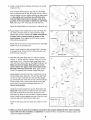
5. The Console (87) requires two "AA" batteries (not
included). Alkaline batteries are recommended. To
install batteries, turn the Console face down and
remove the Battery Cover (97), as shown in the inset
drawing. Next, insert two batteries into the Console.
Make sure that the negative ends of the batteries
(marked "--") are touching the springs in the
Console. Then, reattach the Battery Cover.
26 i
Bookrack
Console
Carefully feed the Resistance Cable (57) down through
the Upright (2) until the end of the Resistance Cable
extends from the bottom of the Upright. Next, connect
the console wire to the Extension Wire (51).
Attach the Console (87) to the Upright (2) with the four
Console Screws (35) and the four Console Washers
(98) packaged with the Console. Be careful to avoid
pinching the wires.
35
Snap the bookrack onto the Console (87) where shown.
6
35
6. Remove the four M10 Nylon Locknuts (not shown)
from the welded bolts on the front of the Frame (1).
6
2
....
Lay a cloth over the front of the Frame (1) to protect it
from scratches. Lay the Upright (2) in the position
shown. Connect the Extension Wire (51) to the Reed
Switch Wire (50).
---
........... _
---
Next, connect the Resistance Cable (57) to the
Extension Cable (93) in the following way:
57
- .......... __]_93
_-__
• Refer to drawing A. Pull up on the metal bracket on
the Extension Cable (93), and insert the tip of the
Resistance Cable (57) into the wire clip on the
Extension Cable as shown.
• Refer to drawing B. Firmly pull the Resistance Cable
(57) and slide it into the metal bracket on the
Extension Cable (93) as shown.
'
Welded Bolts J
50
lJ___
A
C
Metal
Bracket #_
L
I
i i
• Refer to drawing C. Using pliers, squeeze the prongs
on the upper end of the metal bracket together.
93_
7. Align the two holes in the front of the Upright (2) with
the two welded bolts on the front of the Frame (1).
Next, pivot the Upright (2) about halfway to a vertical
position. Refer to the inset drawing. As you raise
the Upright, look into the lower end and make sure
that the metal bracket on the Extension Cable (93)
does not get caught on the Upright or the Frame
(1). In addition, feed all slack Extension Wire (51)
and Reed Switch Wire (50) into the Upright.
Continue to raise the Upright until the four welded
bolts are inserted through the bracket at the bottom of
the Upright.
Lift the front of the Incline Frame (5). Tighten an M10
Nylon Locknut (26) onto each welded bolt.
8. Identify the Left Pedal Arm (3), which has an "L" sticker
on it. Next, identify the Left Pedal (41), which has the
letter "L" molded onto the bottom.
_----_
J3
Welded
Turn over the Left Pedal Arm (3) as shown. Insert the
three plastic posts on the Left Pedal (41) into the three
indicated holes in the Left Pedal Arm. Make sure that
the Left Pedal is turned as shown. Attach the Left
Pedal with three Pedal Screws (43).
Open
Attach the Right Pedal (not shown) to the Right Pedal
Arm (not shown) in the same way.
41
7
_
Side
Plastic Posts
9. Apply a small amount of grease to the axle on the left
Crank Arm (6).
Side a Plastic Pedal Spacer (92) and the Left Pedal
Arm (3) onto the axle on the left Crank Arm (6). Note: It
may be helpful to use a rubber mallet to tap these parts
on. Be careful not to confuse the Left Pedal Arm
with the Right Pedal Arm (not shown); look at the
position of the round tube to identify the Left Pedal
Arm. Next, tap a 3/4" Axle Cap (61) onto the axle.
Attach the Right Pedal Arm (not shown) in the same way.
10.Apply grease to the welded bolt on the Left Pedal Arm
(3). Slide a Chrome Tube (21) and a Chrome Tube
Washer (84) onto the welded bolt. Make sure that the
Chrome Tube is turned exactly as shown in the
inset drawing. Then, tighten an M1O Nylon Locknut
(26) onto the welded bolt.
Tube
10
Wide
Side
Na rrow
Side
1
9[
26 84
Attach the other Chrome Tube (not shown) to the Right
Pedal Arm (4) in the same way.
Apply a small amount of the included Teflon '_ lubricant
to a paper towel. Rub a thin film of the lubricant onto
both Chrome Tubes (21).
26
11. Slide the Left Upper Body Arm (7), which is marked
with an "L" sticker, onto the Chrome Tube (21) on the
Left Pedal Arm (3). Slide the Right Upper Body Arm
(75) onto the Chrome Tube on the Right Pedal Arm (4).
Make sure that the Upper Body Arms are on the
correct sides--the upper ends should bend in the
direction shown by the arrows. Next, slide an Axle
Cover (74) onto the post on each Upper Body Arm.
Welded Bolt
11
Apply grease to the Arm Axle (19). Insert the Arm Axle
into the Right Upper BodyArm (75) and the right Pivot
Cover (74). Next, insert the Arm Axle into the Upright
(2) until the left end of the Axle is flush with the left side
of the Upright. Then, insert the Arm Axle into the left
Axle Cover (74) and the Left Upper Body Arm (7).
Center the Arm Axle.
15
Post
Using the included pedal tool, tap two Push Nuts (15)
about 1/8" onto each end of the Arm Axle (19). Make
sure that the Push Nuts are turned as shown in the
inset drawing. Note: It may be helpful if another person
holds a block of wood against one end of the Arm Axle
while you tap Push Nuts onto the other end.
Pedal Tool 15
19
Press an Axle Cap (34) onto each end of the Arm Axle
(19).
12. Make sure that all parts of the elliptical crosstrainer are properly tightened. Note: Some hardware
may be left over after assembly is completed. To protect the floor or carpet from damage, place a mat
under the elliptical crosstrainer.
8
HOW TO USE THE ELLIPTICAL CROSSTRAINER
EXERCISING ON THE ELLIPTICAL CROSSTRAINER
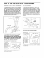
INCLINE ADJUSTMENT
To mount the elliptical crosstrainer, hold the handlebar
and step onto the pedal that is in the lowest position.
Next, step onto the other pedal. Push the pedals until
they begin to move with a continuous motion. Note:
The pedal disks can turn in either direction. It is
recommended that you move the pedal disks in
the direction shown by the arrow below; however,
to give variety to your exercise, you may turn the
pedal disks in the opposite direction.
To further adjust the intensity of your exercise, the
incline frame can be raised or lowered. To raise the
incline frame, position the pedal arms side by side as
shown below. Lift the end of the incline frame until the
crossbar is on top of the incline bracket. Make sure
that the crossbar is resting securely on top of the
incline bracket. To lower the incline frame, lift the
incline frame slightly, push the incline bracket toward
the upright, and then lower the incline frame onto the
stabilizer.
Upright
Incline
-Crossbar
Stabilizer
Incline
Frame
HOW TO USE THE UPPER BODY ARMS
The upper body
arms are designed
to add upper-body
exercise to your
workouts. As you
exercise, hold the
upper body arms
and move your
arms forward and
back in order to
work your arms,
back, and shoulders.
To dismount the elliptical crosstrainer, wait until the
pedals come to a complete stop. The elliptical
crosstrainer
does not have a free wheel; the pedals will continue to move until the flywheel stops.
When the pedals are stationary, step off the highest
pedal first. Then, step off the lowest pedal.
HOW TO ADJUST THE RESISTANCE
To adjust the
resistance of the
pedals as you
exercise, turn the
resistance dial on
the console.
To exercise only your lower body, hold the handlebar
as you exercise.
Turning the dial
clockwise will
increase the
resistance; turning the dial counterclockwise
decrease the resistance.
Upper Body Arms
will
9
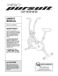
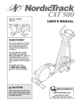
DESCRIPTION
OF THE CONSOLE
TRAINING
"
Book
Holder
.
As you exercise, watch your progress with the training zone display and the liquid-crystal displays.
ZONES
The training zone
display--As
you
exercise, the trainTraining Zone Display .................................................
ing zone display will
show the approxiSCAN CALS, FATCALS,
mate intensity level
of your exercise.
SPEED
TIME DISTANCE
For example, if the fourth indicator in the display is
lit (refer to the drawing above), the display shows
that your intensity level is ideal for fat burning.
The left display-The left display will
show your heart
rate when the pulse
sensor is used (see
step 4 below).
RESISTANCE
_Q
HEART
RATE
The right display-5CAN
CALS, FATCALS,
As you exercise, the
right display will
show your current
SPEED
TiME
DISTANCE
striding speed, the
elapsed time, the
distance you have
traveled, and the numbers of fat calories and calories your have burned (see BURNING FAT on page
12). The display will change from one number to the
next every five seconds. Arrows in the display will
indicate which number is currently shown.
[ hn.nnl
The console offers a selection of features to help you
get the most from your workouts. The water bottle
holders keep your water bottle handy during your
workouts; the book holder lets you read your favorite
magazine while you get in shape; the convenient
resistance dial allows you to easily change the resistance at any time; and the unique training zone display
and the two liquid-crystal displays provide instant
exercise feedback. You can even measure your heart
rate using the built-in pulse sensor.
.
BATTERY INSTALLATION
Before the console can be operated, two "AA" batteries
must be installed. Refer to assembly step 5 on page 6
for installation instructions.
.
HOW TO OPERATE THE CONSOLE
To reset the liquid-crystal displays, press the
on/reset button at any time.
To measure your
heart rate, first peel
the protective
vinyl film off the
four metal contacts on the pulse
sensor.
Note: tf there is a thin sheet of clear plastic on the
face of the console, remove it.
Next, stop exercising and place your
hands on the metal
contacts on the
pulse sensor. Your palms must be resting on the
front contacts and your fingers must be touching
the rear contacts. Avoid moving your hands.
1. To turn on the power, press the on/reset button or
simply begin exercising. When the power is turned
on, the displays and indicators will light for two seconds. The console will then be ready for operation.
10
When your pulse is detected, the heart-shaped
indicator in the left display will begin to flash, one
to three dashes will appear, and then your heart
rate will be shown. For the most accurate heart
rate reading, continue to hold the contacts for about
15 seconds. Note: If your heart rate is not shown,
make sure that your hands are positioned as
described above. Be careful not to move your
hands excessively or squeeze the metal contacts
too tightly.
5. To turn off the power, simply wait for about four
minutes.
Note: The console has an
the pedals are not moved
ton is not pressed for four
will turn off automatically
the batteries.
"auto-off" feature. If
and the console butminutes, the power
in order to conserve
WARN ING: The
pulse sensor
is not a medical device. Various factors
may affect the accuracy of heart rate readings. The pulse sensor is intended only as
an exercise aid in determining heart rate
trends in general.
MAINTENANCE
AND TROUBLESHOOTING
LUBRICATING
Inspect and tighten all parts of the elliptical crosstrainer
regularly. Replace any worn parts immediately.
For smooth
operation of
the elliptical
crosstrainer,
the incline
frame should
be kept clean.
Using a soft
cloth and mild
THE INCLINE BRACKET
The incline
bracket and the
bolt on which it
pivots should be
regularly lubricated. Apply a
small amount of
the included
lubricant to the
bolt and
between the
bracket and the
Frame
Wheel
detergent,
clean dust and
other residue
from the incline
frame where the wheels make contact with it. Other
_-_-_ Upr ght
"
Incline
Bracket
upright.
BATTERY REPLACEMENT
parts of the elliptical crosstrainer can also be cleaned
in this manner. Never use abrasives or solvents.
If the console does not function properly, the batteries
should be replaced. Refer to assembly step 5 on page
6 for instructions. Note: It is not necessary to remove
the console in order to replace the batteries.
To prevent damage to the console, keep liquids away
from the console. Always remove the batteries from
the console when storing the elliptical crosstrainer.
11
CONDITIONING
GUIDELINES
The following guidelines will help you to plan your
exercise program.
WARN ING: Before
Burning Fat
To burn fat, you must exercise at a low intensity level
for a sustained period of time. During the first few
minutes of exercise, your body uses easily accessible
carbohydrate calories for energy. Only after the first few
minutes of exercise does your body begin to use stored
fat calories for energy. If your goal is to burn fat, adjust
the intensity of your exercise until your heart rate is
near the low end of your training zone as you exercise.
this
beginning
or any exercise program, consult your physician. This is especially important for persons
over the age of 35 or persons with pre-existing health problems.
The pulse sensor is not a medical device.
Various factors, including the user's movement, may affect the accuracy of heart rate
readings. The pulse sensor is intended on ly
as an exercise aid in determining heart rate
trends in general.
Aerobic Exercise
If your goal is to strengthen your cardiovascular system, your exercise must be "aerobic." Aerobic exercise
is activity that requires large amounts of oxygen for
prolonged periods of time. This increases the demand
on the heart to pump blood to the muscles, and on the
lungs to oxygenate the blood. For aerobic exercise,
adjust the intensity of your exercise until your heart
rate is near the middle of your training zone.
EXERCISE INTENSITY
Whether your goal is to burn fat or strengthen your
cardiovascular system, the key to achieving the
desired results is to exercise with the proper intensity.
The proper intensity level can be found by using your
heart rate as a guide. For effective exercise, your heart
rate should be maintained at a level between 70% and
85% of your maximum heart rate as you exercise. This
is known as your "training zone." You can find your
training zone in the table below. Training zones are
listed according to age and physical condition.
HOW TO MEASURE YOUR HEART RATE
To measure your heart rate, see step 4 on page 10.
WORKOUT GUIDELINES
Each workout should include three important parts:
(1) a warm-up, (2) training zone exercise, and (3) a
cool-down.
AGE
UNCONDITIONED
TRAINING ZONE
(BEATS/MIN)
CONDITIONED
TRAINING ZONE
(BEATS/MIN)
20
138-167
133-162
25
136-166
132-160
30
135-164
130-158
35
134-162
129-156
40
132-161
127-155
45
131-159
125-153
50
129-156
124-150
Cooling Down--Finish each workout with 5 to 10
minutes of stretching. Stretching after exercise develops flexibility and helps prevent post-exercise problems.
55
127-155
122-149
EXERCISE FREQUENCY
60
126-153
121-147
65
125-151
119-145
70
123-150
118-144
75
122-147
117-142
80
120-146
115-140
Warming up--Warming up prepares the body for
exercise by increasing circulation, delivering more
oxygen to the muscles, and raising the body temperature. Begin each workout with 5 to 10 minutes of
stretching and light exercise to warm up.
Training Zone Exercise--After warming up, increase
the intensity of your exercise until your heart rate is in
your training zone for 20 to 30 minutes.
To maintain or improve your condition, plan three
workouts each week, with at least one day of rest
between workouts. After a few months of regular exercise, you may complete up to five workouts each
week, if desired. The key to success is to make exercise a regular and enjoyable part of your daily life.
12
SUGGESTED
STRETCHES
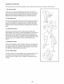
The correct form for several basic stretches is shown below. Move slowly as you stretch--never
1. Toe Touch Stretch
Stand with your knees bent slightly and slowly bend forward from
your hips. Allow your back and shoulders to relax as you reach down
toward your toes as far as possible. Hold for 15 counts, then relax.
Repeat 3 times. Stretches: Hamstrings, back of knees and back.
2. Hamstring
Stretch
Sit with one leg extended. Bring the sole of the opposite foot toward
you and rest it against the inner thigh of your extended leg. Reach
toward your toes as far as possible. Hold for 15 counts, then relax.
Repeat 3 times for each leg. Stretches: Hamstrings, lower back and
groin.
3. Calf/Achilles
Stretch
With one leg in front of the other, reach forward and place your
hands against a wall. Keep your back leg straight and your back foot
flat on the floor. Bend your front leg, lean forward and move your
hips toward the wall. Hold for 15 counts, then relax. Repeat 3 times
for each leg. To cause further stretching of the achilles tendons, bend
your back leg as well. Stretches: Calves, achilles tendons and
ankles.
4. Quadriceps Stretch
With one hand against a wall for balance, reach back and grasp one
foot with your other hand. Bring your heel as close to your buttocks
as possible. Hold for 15 counts, then relax. Repeat 3 times for each
leg. Stretches: Quadriceps and hip muscles.
5. Inner Thigh Stretch
Sit with the soles of your feet together and your knees outward. Pull
your feet toward your groin area as far as possible. Hold for 15
counts, then relax. Repeat 3 times. Stretches: Quadriceps and hip
muscles.
13
bounce.
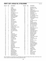
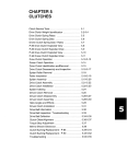
PART LIST--Model
Key No.
Qty.
1
2
3
4
5
6
7
8
9
10
11
12
13
14
15
16
17
18
19
20
21
22
23
24
25
26
27
28
29
30
31
32
33
34
35
36
37
38
39
40
41
42
43
44
45
46
47
48
49
50
51
52
1
1
1
1
1
2
1
1
2
1
1
1
1
2
4
1
3
2
1
2
2
4
6
1
1
15
1
1
1
2
6
4
2
2
4
1
1
2
1
2
1
1
6
3
2
2
1
1
1
1
1
1
No. NTEL05900
Description
Rl101A
Key No.
Qty.
53
54
55
56
57
58
59
60
61
62
63
64
65
66
67
68
69
70
71
72
73
74
75
76
77
78
79
80
81
82
83
84
85
86
87
88
89
90
91
92
93
94
95
96
97
98
#
#
#
#
#
1
1
1
4
1
2
1
2
2
2
4
2
1
1
2
1
1
1
1
10
6
2
1
4
2
4
2
3
4
4
2
2
1
2
1
4
2
1
1
2
1
1
1
1
1
4
1
1
1
2
1
Frame
Upright
Left Pedal Arm
Right Pedal Arm
Incline Frame
Crank Arm
Left Upper Body Arm
Large Pulley
Frame Bearing
Plastic Crank Spacer
Flat Delrin Washer
Idler Bracket
Pulley
Idler Bearing
Push Nut
Idler Arm Screw
M10 Flat Washer
Foam Grip
Arm Axle
Plastic Arm Sleeve
Chrome Tube
Extension Tube Bushing
Arm Bushing
Incline Bracket
M10 x 85mm Bolt
M10 Nylon Locknut
Hook
Belt
Incline Axle
Incline Axle Screw
Incline Bushing
Incline Frame Cap
M8 Washer
Pivot Axle Cap
Console Screw
Spring
Flywheel
Flywheel Bearing
Flywheel Axle
Pedal Disk
Left Pedal
Right Pedal
Pedal Screw
Resistance Control Screw
Wheel
Wheel Bolt
Left Side Shield
Right Side Shield
Console Base
Reed Switch/Wire
Extension Wire
Reed Switch Bracket
Description
Resistance Knob
Reed Switch Clamp
Magnet
Clamp Washer
Resistance Control/Cable
M8 Split Washer
Clamp Bolt
Rear Stabilizer Bolt
3/4" Axle Cap
Front Stabilizer Endcap
Pedal Arm Cap
Rear Stabilizer Endcap
"J" Bolt Nut
"J" Bolt
M10 Nylon Jam Nut
Eyebolt
M6 Nylon Locknut
Adjustment Bracket
M4 x 63.5mm Screw
M4 x 16mm Screw
M5 x 16mm Screw
Axle Cover
Right Upper Body Arm
Pedal Bushing
Pedal Wheel
Pedal Wheel Bearing
Pedal Wheel Bolt
M8 Nylon Locknut
M8 Black Washer
Wheel Spacer
Flange Bolt
Chrome Tube Washer
Clamp Nut
Front Stabilizer Bolt
Console
M5 x 25mm Screw
Stop Nut
Front Stabilizer
Side Shield Support
Plastic Pedal Spacer
Extension Cable
Rear Stabilizer
Stop Nut
"C" Magnet
Battery Cover
Console Washer
Grease
Teflon ®Lubricant
Push Nut Tool
Allen Wrench
User's Manual
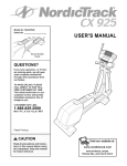
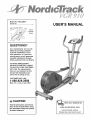
Note: # indicates a non-illustrated part. Specifications are subject to change without notice. See the back cover
of this manual for information about ordering replacement parts.
14
88
73
_T
87
4O
0
0
i
34
23.
72
0
,,--I,
72
44
76 61
o
78
37
70
63
84
\
25
51
9O
32
29
33
3O
4O
,9
46
64
61_
76
63
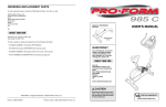
HOW TO ORDER REPLACEMENT
PARTS
To order replacement parts, simply call our Customer Service Department toll-free at 1-888-825-2588, Monday
through Friday, 6 a.m. until 6 p.m. Mountain Time (excluding holidays). To help us assist you, please be
prepared to give the following information when calling:
• The MODEL NUMBER of the product (NTEL05900)
• The NAME of the product (NordicTrack '_VGR910 elliptical crosstrainer)
• The SERIAL NUMBER of the product (see the front cover of this manual)
• The KEY NUMBER and DESCRIPTION
of the part(s) from page 14 of this manual.
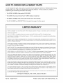
LI MITED WARRANTY
WHAT IS COVERED--The
material and workmanship.
WHO IS COVERED--The
entire NordicTractP
VGR910
elliptical
crosstrainer
("Product")
is warranted
to be free of all defects in
original purchaser or any person receiving the Product as a gift from the original purchaser.
HOW LONG IS IT COVERED--ICON
Labor is covered for one year.
Health & Fitness, Inc. ("ICON"), warrants the product for one year after the date of purchase.
WHAT WE DO TO CORRECT COVERED DEFECTS--We will ship to you, without charge, any replacement part or component, providing the repairs are authorized by ICON first and are performed by an ICON trained and authorized service provider, or, at our
option, we will replace the Product.
WHAT IS NOT COVERED--Any
failures or damage caused by unauthorized service, misuse, accident, negligence, improper assembly or installation, alterations, modifications without our written authorization or by failure on your part to use, operate, and maintain
as set out in your User's Manual ("Manual").
WHAT YOU MUST DO--Always
retain proof of purchase, such as your bill of sale; store, operate, and maintain the Product as specified in the Manual; notify our Customer Service Department of any defect within 10 days after discovery of the defect; as instructed, return any defected part for replacement or, if necessary, the entire product, for repair.
USER'S MANUAL--It
periodic maintenance
is VERY IMPORTANT THAT YOU READ THE MANUAL before operating the Product. Remember to do the
requirements specified in the Manual to assure proper operation and your continued satisfaction.
HOW TO GET PARTS AND SERVICE--Simply
call our Customer Service Department at 1-888-825-2588 and tell them your name
and address and the serial number of your Product. They will tell you how to get a part replaced, or if necessary, arrange for service
where your Product is located or advise you how to ship the Product for service. Before shipping, always obtain a Return
Authorization Number (RA No.) from our Customer Service Department; securely pack your Product (save the original shipping carton if possible); put the RA No. on the outside of the carton and insure the product. Include a letter explaining the product or problem and a copy of your proof of purchase if you believe the service is covered by warranty.
ICON is not responsible or liable for indirect, special or consequential damages arising out of or in connection with the use or performance of the product or damages with respect to any economic loss, loss of property, loss of revenues or profits, loss of enjoyment or use, costs of removal, installation or other consequential damages of whatsoever nature. Some states do not allow the exclusion or limitation of incidental or consequential damages. Accordingly, the above limitation may not apply to you.
The warranty extended hereunder is in lieu of any and all other warranties and any implied warranties of merchantability or fitness
for a particular purpose is limited in its scope and duration to the terms set forth herein. Some states do not allow limitations on how
long an implied warranty lasts. Accordingly, the above limitation may not apply to you.
No one is authorized to change, modify or extend the terms of this limited warranty. This warranty gives you specific legal rights and
you may have other rights which vary from state to state.
ICON HEALTH & FITNESS, INC., 1500 S. 1000 W., LOGAN, UT 84321-9813
Part No. 172092 R1101A
Printed in China © 2001 iCON Health & Fitness, inc.