1
Technical Documentation
Multi-Function Technology (MFT)
for Damper and Control Valve Applications
Effective May 2010
Multi-Function Technology®
Your swiss army knife for HVAC.
We set standards.
www.belimo.com
Features and benefits only
Belimo's MFT can provide.
Multi-Function Technology, only from
solutions for individual applications, using
the same programmable actuator.
Whether you need a particular control or
feedback signal, or need to change
running speeds, MFT is the answer. It
comes standard as a 2 to 10 VDC
Feature
Benefit
proportional control but can be
Configurable control and
feedback signal type
Reduced number of actuators
required in stock
Variable runtime
Flexibility to tune to each application
Flexible angle of rotation setting
Customized to fit application - to drive
actuator less than 100% open/closed
Scalable operating range
Optimized control resolution
for every operating range
Min, Mid, Max override function
Additional system control beyond
modulation
status and diagnostics. Think of it as your
Stored alarm information
Ease troubleshooting
all-in-one, swiss army knife for HVAC.
Data logging capability
Gather system data for optimization
or diagnostics
reprogrammed on-site. You can modify
voltage control, time proportional control,
floating point, on/off and feedback
signals too. In addition, MFT makes it
easy to set parameters for running time,
mechanical working range, address,
L30014 - 04/10 - Subject to change. © Belimo Aircontrols (USA), Inc.
Belimo, allows you to create custom
MULTI-FUNCTION TECHNOLOGY
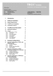
Table of Contents
Belimo damper actuators and control valves with Multi-Function
MULTI-FUNCTION TECHNOLOGY
Nomenclature . . . . . . . . . . . . . . . . . . . . . . . . . . . . . . . 2
MFT Overview. . . . . . . . . . . . . . . . . . . . . . . . . . . . . . . 3
Spring Return Actuator Product Range
Multi-Function Technology . . . . . . . . . . . . . . . . . . . . . 4
Non-Spring Return Actuator Product Range
Multi-Function Technology . . . . . . . . . . . . . . . . . . . . . 5
Pre-Set MFT Configurations . . . . . . . . . . . . . . . . . . . . 6
Pulse Width Modulation Control. . . . . . . . . . . . . . . . . 7
Flow Point Control . . . . . . . . . . . . . . . . . . . . . . . . . . . 8
On/Off Control . . . . . . . . . . . . . . . . . . . . . . . . . . . . . . 9
MFT Operation . . . . . . . . . . . . . . . . . . . . . . . . . . . . . 10
MFT Specifications/Descriptions . . . . . . . . . . . . . . . 14
Wiring. . . . . . . . . . . . . . . . . . . . . . . . . . . . . . . . . . . . 16
Programming Codes . . . . . . . . . . . . . . . . . . . . . . . . 20
Technology (MFT) are an excellent way to standardize your product
line while reducing the number of different actuators needed. MultiFunction Technology offers a wide variety
of programmable control inputs and
feedback signals. Parameters can be set
for voltage control (VDC), time proportional control (PWM), floating
point, on-off, feedback signal, or torque output. Parameters can be
changed on-site to optimize/enable application. You can also set, modify
or read position, running time, mechanical working range, address,
status, and diagnostics.
MFT offers tailor made solutions allowing you to adapt the actuator
PC-TOOL ACCESSORIES
Software
MFT-P US . . . . . . . . . . . . . . . . . . . . . . . . . . . . . . . . . 35
Interfaces
ZIP-USB-MP US . . . . . . . . . . . . . . . . . . . . . . . . . . . . 36
ZIP-RS232 US . . . . . . . . . . . . . . . . . . . . . . . . . . . . . 37
MFT Cables. . . . . . . . . . . . . . . . . . . . . . . . . . . . . . . . 38
of valve to your system for replacement and to improve system
functionality.
M40035 - 05/10 - Subject to change. © Belimo Aircontrols (USA), Inc.
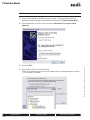
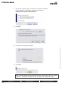
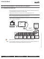
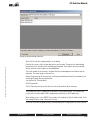
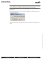
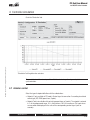
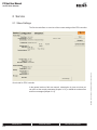
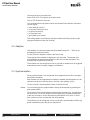
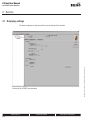
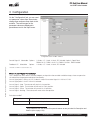
BELIMO PC-TOOL
Laptop access anywhere.
Universal Access to all MFT actuators.
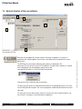
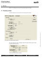
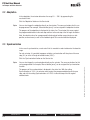
The PC-Tool is a universal software application for setting,
commissioning, monitoring and evaluating communications with
Belimo actuators. Actuators are normally delivered with the basic
settings. They can be individually programmed using the PC-Tool
and precisely adjusted to the requirements of the system. Service related
diagnostics for the actuators are extremely easy with the PC-Tool.
Setpoints can be specified and actual values monitored The trend
recording function can output the information in a graphical format for
system documentation.
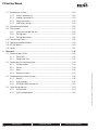
USER MANUALS
PC-Tool User Manual . . . . . . . . . . . . . . . . . . . . . . . 1-A
Introduction . . . . . . . . . . . . . . . . . . . . . . . . . . . . . . 1-1
Configuration . . . . . . . . . . . . . . . . . . . . . . . . . . . . 1-29
PC-Tool Options . . . . . . . . . . . . . . . . . . . . . . . . . . 1-40
Damper and Valve Actuators User Manual . . . . . . . . 2-A
Introduction . . . . . . . . . . . . . . . . . . . . . . . . . . . . . . 2-1
Service . . . . . . . . . . . . . . . . . . . . . . . . . . . . . . . . . . 2-2
Configuration . . . . . . . . . . . . . . . . . . . . . . . . . . . . . 2-7
Controller Simulation . . . . . . . . . . . . . . . . . . . . . . 2-14
PC-Tool Options . . . . . . . . . . . . . . . . . . . . . . . . . . 2-18
NV/NVF Series Actuators User Manual . . . . . . . . . . . 3-A
Introduction . . . . . . . . . . . . . . . . . . . . . . . . . . . . . . 3-3
Service . . . . . . . . . . . . . . . . . . . . . . . . . . . . . . . . . . 3-4
Configuration . . . . . . . . . . . . . . . . . . . . . . . . . . . . . 3-7
Controller Simulation . . . . . . . . . . . . . . . . . . . . . . 3-11
PC-Tool Options . . . . . . . . . . . . . . . . . . . . . . . . . . 3-15
ePIV Series User Manual . . . . . . . . . . . . . . . . . . . . 4-A
Introduction . . . . . . . . . . . . . . . . . . . . . . . . . . . . . . 4-3
Service . . . . . . . . . . . . . . . . . . . . . . . . . . . . . . . . . . 4-4
Configuration . . . . . . . . . . . . . . . . . . . . . . . . . . . . . 4-9
Controller Simulation . . . . . . . . . . . . . . . . . . . . . . 4-12
PC-Tool Options . . . . . . . . . . . . . . . . . . . . . . . . . . 4-16
SY Series User Manual . . . . . . . . . . . . . . . . . . . . . 5-A
Introduction . . . . . . . . . . . . . . . . . . . . . . . . . . . . . . 5-3
Service . . . . . . . . . . . . . . . . . . . . . . . . . . . . . . . . . . 5-4
Configuration . . . . . . . . . . . . . . . . . . . . . . . . . . . . . 5-7
Controller Simulation . . . . . . . . . . . . . . . . . . . . . . 5-11
PC-Tool Options . . . . . . . . . . . . . . . . . . . . . . . . . . 5-15
800-543-9038 USA
866-805-7089 CANADA
203-791-8396 LATIN AMERICA
1
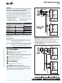
Multi-Function Technology®
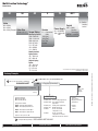
Nomeclature
50
AR
X
24
-MFT
-S = Built-in
Auxiliary
Switch
Valve
B2 = 2-Way
B3 = 3-Way
B6 = 2-Way Flanged
Control
Power Supply -MFT = Multi-
Valve Size
07-80 = 1/2”- 3”
Torque Rating
Version
X* = Customized
Non-Spring Return
Cable
GM = 360 in-lb
10 ft (3m)
AM = 180 in-lb
16 ft (5m)
NM = 90 in-lb
Run Time
LM = 45 in-lb
Variable
LU = 27 in-lb
AH = 220 lbf
LH = 100 lbf
New Generation
Spring Return
AF = 180 in-lb
NF = 90 in-lb
Original Spring
Return
AF = 133 in-lb
NF = 60 in-lb
LF = 35 in-lb
TF = 18 in-lb
24 = 24 VAC/DC
120 = 120 to 230
VAC
Function
Technology
-MFT95** = 0-135 Ω
* Only available on New Generation Spring Return and Non-Spring
** Not Available on NF, LF and TF
Ordering Example
3
1
For MFT orders only - select programming code
Choose the valve actuator combination.
B250+ARX24-MFT
+NO
+Tagging (if needed)
4
2
Specify preference or configuration.
Does order
require
tagging?
Set-Up
P-10001 (A01)
Non-Spring Models
NO = Normally Open
NC = Normally Closed
Spring Return Models
NO/FO = Normally Open/Fail Open
NO/FC = Normally Open/Fail Closed
NC/FO = Normally Closed/Fail Open
NC/FC = Normally Closed/Fail Closed
Refers to valve ports A to AB.
5
Complete Ordering Example:
800-543-9038 USA
2
P-100xx (Axx) Control voltage applications
P-200xx (Wxx) Pulse width modulation
applications
P-300xx (Fxx) Floating Point applications
P-400xx (Jxx) On/Off applications
X-XXXXX
Create custom MFT
configuration code
X-XXXXX
Create custom MFT
configuration in the field
with MFT-actuator PC software
Tagging:
Valves may be
tagged per customer
specification.
Example:
AHU-1
FCU-2
B250+ARX24-MFT+NO+A01
866-805-7089 CANADA
203-791-8396 LATIN AMERICA
M40035 - 05/10 - Subject to change. © Belimo Aircontrols (USA), Inc.
B2
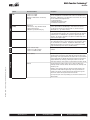
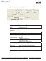
Multi-Function Technology®
Control
Parameter Variables
Description
VDC
• Start: 0.5 to 30 VDC
• Stop: 2.5 to 32 VDC
(Minimum 2 VDC between start and stop
required)
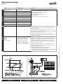
P-100…(A…) configuration types are used for VDC control applications.
Pre-set configurations are listed which offer solutions for standard control
applications. Additional pre-set configurations are list which offer solutions
for non-standard control application for:
• Sequencing Actuators
• Adjustable Start and Stop Points
• Combination for Master Slave
Pulse Width Modulation
(PWM)
PWM Range
• 0.02 to 50 sec. range minimum interval
• 20 [ms] between pulses
• Minimum cycle duration 520 [ms]
P-200… (W…) configuration types are used for pulse width modulation
control outputs with four standard ranges. There must be at least one
second between the min pulses allowed (0.02 sec.) and the max pulse
allowed (50 sec.). (eg: 0.02 to 1.02 sec.)
Floating Point
P-300… (F...) configuration types are used for floating point control outputs.
In this application MFT actuators offer constant running time and standard
feedback options. A 1N4004 diode is required for original spring return
actuators. The actuator is designed to recognize the rectified voltage as an
opposite control signal request.
On/Off
P-400… (J…) configuration types are used for on/off control outputs.
The configuration allows for service replacement of on/off actuators when a
true on/off actuator is not available. In addition the MFT actuator offers
additional functionality in the on/off mode, such as configuration P-40003
(J03) with minimum position and 2 to 10 VDC feedback.
Position Feedback
Position Feedback Range
• Start: 0.5 to 8 VDC Selectable
• Stop: 2 to 10 VDC Selectable
The default-operating mode of the U5 output is 2 to 10 VDC for position
feedback.
Control Sensitivity
Normal (Default)
MFT actuators are designed with a unique non-symmetrical dead band. The
actuator follows an increasing control signal with a 80 mV resolution. If the
signal changes in the opposite direction, the actuator will no respond until the
control signal changes by 200 mV. This allows the actuator to track even the
slightest deviation very accuratly, yet allowing the actuator to "wait" for a
much larger change in control signal. For quick actuators the values are half.
Reduced
Upon detecting an un-stable control loop, the "reduced" setting can be
manually selected via the PC software. This will reduce the sensitivity of the
actuator by 50%.
Sensitivity
M40035 - 05/10 - Subject to change. © Belimo Aircontrols (USA), Inc.
Feedback
Input
Overview
Meaning, control accuracy will now be 160 mV for signal changes in the
same direction. And a 400 mV signal change in the opposite direction is
needed for the actuator to change direction. Once driving in the opposite
direction the actuator will respond in 160 mV increments.
Upon improving the control loop stability you can return the actuator to the
"Normal" mode.
800-543-9038 USA
866-805-7089 CANADA
203-791-8396 LATIN AMERICA
3
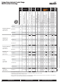
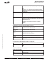
Spring Return Actuator Product Range
Multi-Function Technology
VDC Variable, Start 0 to 8,
Span 2 to 10 VDC
●
●
●
●
AFX24-MFT-S†
●
70…220 (150) <20♦
●
10 7.5 (3.0)
●
●
●
●
●
●
●
AFX24-MFT95†
70…220 (150) <20♦
●
10 7.5 (3.0)
●
●
●
AF24-MFT US†
75…300 (150)
<20
●
10 6.0 (2.5)
●
●
●
●
●
●
●
AF24-MFT-S US†
75…300 (150)
<20
●
10 6.0 (2.5)
●
●
●
●
●
●
●
AF24-MFT95 US†
75…300 (150)
<20
●
10 6.0 (2.5)
●
●
●
Spring Return
2 SPDT, 7 A (2.5 A inductive) @ 250V
2-10 VDC (Default)
●
2 SPDT, 3 A (0.5 A inductive) @ 250V
PWM adj., 0.02 to 50.0 Seconds
●
1 SPDT, 3 A (0.5 A inductive) @ 250V
Start and Span adj., Start 0.5 to
30 VDC, Span 2.5 to 32 VDC
●
Honeywell Series 90, 0-135 Ω
10 7.5 (3.0)
6 - 9 VDC, 20 VDC Output Voltage
●
2-10 VDC (Default)
4-20 mA* (w/500 Ω Resistor)
70…220 (150) <20♦
Wattage Running (Holding)
●
Motor Drive, (Default) (Fully
programmable by Belimo or in field)
AFX24-MFT†
10 ft (3m) cable / 16 ft (5m) cable
Floating Point
Auxiliary
Switches
NEMA
4
Enclosure (Part Number + N4)
Control Input
Control
Input
On/Off
Power
Power
Supply Consumption
VA Rating, Transformer Sizing
Running Rime
24 VAC +/- 20%, VDC +/- 10%, 50/60 HZ
Cable
Options
●
New Generation AFX Series
180 in-lb [20 Nm]
Approx. 45 sq. ft.*
●
●
●
●
Original AF Series
New Generation NFX Series
90 in-lb [10 Nm]
Approx. 22 sq. ft.*
●
NFX24-MFT
●
40…220 (150) <20♦
●
9
6.5 (3.0)
●
●
●
●
●
●
●
NFX24-MFT-S
●
40…220 (150) <20♦
●
9
6.5 (3.0)
●
●
●
●
●
●
●
NF24-MFT US
75…300 (150) <60♦
●
6 3.0 (1.8)
●
●
●
●
●
●
●
LF24-MFT US
75…300 (150) <25♦
●
5
2.5 (1.0)
●
●
●
●
●
●
●
LF24-MFT-S US
75…300 (150) <25♦
●
5
2.5 (1.0)
●
●
●
●
●
●
●
●
●
●
●
Original NF Series
60 in-lb [7 Nm]
Approx. 15 sq. ft.*
LF Series
35 in-lb [4 Nm]
Approx. 8 sq. ft.
LF24-MFT-20 US
150
<25♦
●
6
3.5 (1.5)
●
●
●
●
●
●
●
LF24-MFT-S-20 US
150
<25♦
●
6
3.5 (1.5)
●
●
●
●
●
●
●
75…300 (150) <25♦
●
4
2.0 (1.0)
●
●
●
●
●
●
●
●
TF Series
18 in-lb [2 Nm]
Approx. 4.5 sq. ft.*
TF24-MFT US
●
♦ <60 seconds @ -22°F [-30°C].
† Dual mounting on a single shaft-MFT wired master slave. Please refer to page XX or call Belimo customer service for details.
* Parallel blade without edge seals and 1000 FPM face velocity.
NOTE: Some spring and non-spring damper actuators are also used for water applications. A linkage connects the actuators to the valve. Some of the valves, such as the PICCV use
a running time of 100 seconds. Some actuators end with an X1 such as AMX24-MFTX1.
800-543-9038 USA
4
866-805-7089 CANADA
203-791-8396 LATIN AMERICA
M40035 - 05/10 - Subject to change. © Belimo Aircontrols (USA), Inc.
133 in-lb [15 Nm]
Approx. 33 sq. ft.*
Control Input
Floating Point
Start and Span adj., Start 0.5 to
30 VDC, Span 2.5 to 32 VDC
PWM adj., 0.02 to 50.0 Seconds
2-10 VDC (Default)
VDC Variable, Start 0 to 8,
Span 2 to 10 VDC
Add-on
●
●
●
●
●
4.0 (1.5)
●
GMX24-MFT95†
●
100-300 (150) ●
7
4.0 (1.5)
AMX24-MFT
●
90-300 (150) ●
6
3.5 (1.3)
●
●
●
●
AMCX24-MFT
●
35-120 (35)
●
6
3.5 (1.3)
●
●
●
●
AMX24-MFT95
●
90-150 (150) ●
6
3.5 (1.3)
AMQX24-MFT
●
●
18
12 (1.5)
●
●
●
●
NMX24-MFT
●
45-150 (150) ●
6
3.5 (1.3)
●
●
●
●
NMX24-MFT95
●
45-150 (150) ●
6
3.5 (1.3)
NMCX24-MFT
●
20-75 (20)
●
5
3.0 (0.6)
●
NMQX24-MFT
●
4-20 (4)
●
18
12 (1.5)
●
●
●
●
LMX24-MFT
●
35-200 (150) ●
5
2.5 (1.2)
●
●
●
●
LMX24-MFT95
●
35-150 (150) ●
5
2.5 (1.2)
LMQ Series 35 in-lb [4Nm]
LMQX24-MFT
●
2.5-10 (2.5)
●
18
12 (1.5)
●
●
●
●
AHX Series 101 lbf [450 N Force]
4” or 8” stroke
AHX24-MFT*
●
150*
●
6
3.5 (1.3)
●
●
●
●
AHQ Series 44 lbf [200 N Force]
AHQX24-MFT-100
●
7-30 (7)*
●
18
12 (1.5)
●
●
●
LHX Series 34 lbf [150 N Force]
4” or 8” stroke
LHX24-MFT*
●
75-150 (150)* ●
5
2.5 (1.2)
●
●
LHQ Series 22 lbf [100 N Force]
LHQX24-MFT-100
●
3.5-15 (3.5)* ●
18
12 (1.5)
●
LUX Series 27 in-lb [3 Nm]
LUX24-MFT
●
75-150 (150) ●
5
2.5 (1.2)
●
AMQ Series 140 in-lb [16Nm]
NMX Series 70 in-lb [8 Nm]
Approx. 22 sq. ft.**
NMQ Series 70 in-lb [8Nm]
LMX Series 35 in-lb [4 Nm]
Approx. 11 sq. ft.**
7-15 (7)
100 to 240 VAC
7
Terminal strip
NEMA 1/IP20 / 2/IP54
75-300 (150) ●
●
●
●
●
●
●
●
●
●
●
●
●
●
●
●
●
●
●
●
●
●
●
●
●
●
●
●
●
●
●
●
●
●
●
●
●
●
●
●
●
●
●
●
●
●
●
●
●
●
●
●
●
●
●
●
●
●
●
●
●
●
●
●
●
●
●
●
●
Enclosure (Part No. +N4 or +N4H)
On/Off
●
●
AMX Series 180 in-lb [20 Nm]
Approx. 45 sq. ft.**
Position Auxiliary NEMA
Feedback Switches 4X
●
2-10 VDC (Default)
4-20 mA (w/500 Ω Resistor)
Honeywell Series 90, 0-135 Ω
Control
Input
Wattage Running
(Holding)
Power
Consumption
VA Rating
Power
Supply
GMX24-MFT†
GMX Series 360 in-lb [40 Nm]
Approx. 90 sq. ft.**
M40035 - 05/10 - Subject to change. © Belimo Aircontrols (USA), Inc.
Running
Time
Motor Drive Range, (Default)
…-MFT Fully Programmable
10 ft (3m) cable / 16 ft (5m) cable
Custom
Options
24 VAC +/- 20%, VDC +/- 10%
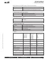
Non-Spring Return Actuator Product Range
Multi-Function Technology
●
●
* The LH and AH linear series actuators come in three different stroke lengths [4, 8 or 12 in]. The part number is followed by -100, -200, -300 respectively. The default
running time is 150 seconds per 4 inches [100 mm]. Running time is adjustable depending on model:
LH Series: 70-270, 140-540, 200-810, on the -100, -200, -300 models respectively.
AH Series: 150-600, 300-1200, 450-1800, on the -100, -200, -300 models respectively.
LHQ and AHQ available in 4 inch version only.
† Dual mounting on a single shaft is possible for higher torque (-3 and -SR wired in parallel), (-MFT wired Master-Slave). Please call Belimo customer service for details.
** Parallel blade without edge seals and 1000 FPM face velocity.
800-543-9038 USA
866-805-7089 CANADA
203-791-8396 LATIN AMERICA
5
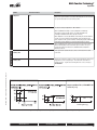
Pre-Set MFT Configurations
DC Voltage Control
Spring Return Actuators
Application
AFX24-MFT(-S)
180 in-lb
AF24-MFT(-S) US
133 in-lb
NFX24-MFT(-S)
90 in-lb
NF24-MFT US
60 in-lb
LF24-MFT(-S) US
35 in-lb
LF24-MFT(-S)-20 US
35 in-lb
TF24-MFT US
18 in-lb
How the MFT actuator performs is determined by the configuration (P-10001,
A01). The old generation actuators used a P-code (P-10001). The new
generation actuators use a shorter 3 digit code. This shorter code is displayed
on the reorder number.
P-1000... configuration types are used for control voltage applications.
Additional pre-set configurations are listed which offer solutions for nonstandard control application for:
• Adjustable Start and Stop points
• Sequencing actuators
• Combination for master slave (see page 19.)
GMX24-MFT
360 in-lb
AMX24-MFT
180 in-lb
NMX24-MFT
90 in-lb
LMX24-MFT
45 in-lb
AMQX24-MFT
140 in-lb
NMQX24-MFT
70 in-lb
LMQX24-MFT
35 in-lb
AHX24-MFT
101 lbf
AHQX24-MFT-100
44 lbf
LHX24-MFT
34 lbf
LHQX24-MFT-100
22 lbf
LUX24-MFT
27 in-lb
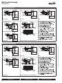
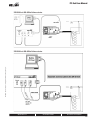
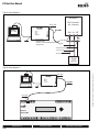
Wiring Diagram
W040
Non-Spring Return Actuators
24 VAC/DC Transformer
Line
Volts
(1)
Common
(2)
+ Hot
(3)
Y Input
(5)
U Output
(–)
Control Signal (+)
(–)
Position Feedback
(+)
CCW CW
…MFT
VDC
Configuration
Code
Input Range
Position Feedback
Running Time
Torque %
Adaptation
P-10001*
A01
2.0 to 10.0 VDC
2.0 to 10.0 VDC
150
100
MANUAL
P-10002
A02
0.5 to 10.0 VDC
0.5 to 10.0 VDC
150
100
MANUAL
P-10003
A03
2.0 to 10.0 VDC
0.5 to 5.0 VDC
150
100
MANUAL
P-10004
A04
4.0 to 7.0 VDC
2.0 to 10.0 VDC
150
100
MANUAL
P-10005
A05
6.0 to 9.0 VDC
2.0 to 10.0 VDC
150
100
MANUAL
P-10006
A06
10.5 to 13.5 VDC
2.0 to 10.0 VDC
150
100
MANUAL
P-10007
A07
0.5 to 5.0 VDC
2.0 to 10.0 VDC
150
100
MANUAL
P-10008
A08
0.5 to 5.0 VDC
0.5 to 10.0 VDC
150
100
MANUAL
P-10009
A09
5.0 to 10.0 VDC
2.0 to 10.0 VDC
150
100
MANUAL
P-10010
A10
5.0 to 10.0 VDC
0.5 to 10.0 VDC
150
100
MANUAL
P-10013
A13
0.5 to 10.0 VDC
2.0 to 10.0 VDC
150
100
MANUAL
P-10015
A15
2.0 to 5.0 VDC
2.0 to 10.0 VDC
150
100
MANUAL
P-10016
A16
2.0 to 6.0 VDC
2.0 to 10.0 VDC
150
100
MANUAL
P-10017
A17
6.0 to 10.0 VDC
2.0 to 10.0 VDC
150
100
MANUAL
P-10018
A18
14.0 to 17.0 VDC
2.0 to 10.0 VDC
150
100
MANUAL
P-10020
A20
9.0 to 12.0 VDC
2.0 to 10.0 VDC
150
100
MANUAL
P-10031
A31
0.5 to 4.0 VDC
2.0 to 10.0 VDC
150
100
MANUAL
P-10063
A63
0.5 to 4.5 VDC
0.5 to 4.5 VDC
150
100
MANUAL
P-10064
A64
5.5 to 10.0 VDC
5.5 to 10.0 VDC
150
100
MANUAL
P-10091
A91
2.0 to 10.0 VDC
2.0 to 10.0 VDC
95
100**
MANUAL
* P-10001 (A01) is the default configuration code.
** Reduced torque in Spring Return (see page 19)
800-543-9038 USA
6
866-805-7089 CANADA
203-791-8396 LATIN AMERICA
M40035 - 05/10 - Subject to change. © Belimo Aircontrols (USA), Inc.
Voltage
Select Configuration
Pre-Set MFT Configurations
Pulse Width Modulation Control
Spring Return Actuators
Application
AFX24-MFT(-S)
180 in-lb
AF24-MFT(-S) US
133 in-lb
NFX24-MFT(-S)
90 in-lb
NF24-MFT US
60 in-lb
LF24-MFT(-S) US
35 in-lb
LF24-MFT(-S)-20 US
35 in-lb
TF24-MFT US
18 in-lb
How the MFT actuator performs is determined by the configuration (P-10001,
A01). The old generation actuators used a P-code (P-10001). The new
generation actuators use a shorter 3 digit code. This shorter code is displayed
on the reorder number.
P-2000… configuration types are used for Pulse Width Modulation control
outputs. Most D.D.C. controllers have digital outputs which incorporate a default
PWM range.
This enables a D.O. to be used as a proportional output when needed. Simply
select the appropriate configuration code according to your application.
Non-Spring Return Actuators
360 in-lb
AMX24-MFT
180 in-lb
NMX24-MFT
90 in-lb
LMX24-MFT
45 in-lb
AH24-MFT
101 lbf
LH24-MFT
44 lbf
LUX24-MFT
27 in-lb
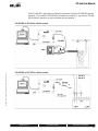
Wiring Diagram
W041MFT
GMX24-MFT
Select Configuration
Pulse Width Modulation
M40035 - 05/10 - Subject to change. © Belimo Aircontrols (USA), Inc.
PWM, Triac Source and Sink
Configuration
Code
Input Range
Position Feedback
Running Time
Torque %
Adaptation
P-20001
W01
0.59 to 2.93 sec
2.0 to 10.0 VDC
150
100
MANUAL
P-20002
W02
0.02 to 5.00 sec
2.0 to 10.0 VDC
150
100
MANUAL
P-20003
W03
0.10 to 25.50 sec
2.0 to 10.0 VDC
150
100
MANUAL
P-20004
W04
0.10 to 25.60 sec
2.0 to 10.0 VDC
150
100
MANUAL
P-20005
W05
0.10 to 5.20 sec
0.5 to 5.0 VDC
150
100
MANUAL
P-20012
W12
0.50 to 25.50 sec
0.5 to 10.0 VDC
150
100
MANUAL
P-20013
W13
0.50 to 2.93 sec
0.5 to 5.0 VDC
150
100
MANUAL
P-20014
W14
0.10 to 10.00 sec
2.0 to 10.0 VDC
150
100
MANUAL
800-543-9038 USA
866-805-7089 CANADA
203-791-8396 LATIN AMERICA
7
Pre-Set MFT Configurations
Floating Point Control
Spring Return Actuators
Application
AFX24-MFT(-S)
180 in-lb
AF24-MFT(-S) US
133 in-lb
NFX24-MFT(-S)
90 in-lb
NF24-MFT US
60 in-lb
35 in-lb
LF24-MFT(-S)-20 US
35 in-lb
TF24-MFT US
18 in-lb
P-3000… configuration types are used for floating point control outputs. In this
application MFT actuators offer constant running time and standard feedback
options. A IN4004 or IN4007 diode is required for original spring return
actuators only.
Wiring Diagram
W042_08
LF24-MFT(-S) US
How the MFT actuator performs is determined by the configuration (P-10001,
A01). The old generation actuators used a P-code (P-10001). The new
generation actuators use a shorter 3 digit code. This shorter code is displayed
on the reorder number.
Non-Spring Return Actuators
GMX24-MFT
360 in-lb
AMX24-MFT
180 in-lb
NMX24-MFT
90 in-lb
LMX24-MFT
45 in-lb
AHX24-MFT
101 lbf
LHX24-MFT
34 lbf
LUX24-MFT
27 in-lb
24 VAC Transformer (AC only)
Diode may be placed at
the control panel.
Reduces field wiring
Line
Volts
Hot
COM
Triac Sink
Wiring 6
(1)
Common
4
(2)
+ Hot
5
(3)
Y Input
(5)
U Output
CCW CW
A
…MFT
1
2
Controller
Position
Feedback
B
3
Floating Point
NOTE: Diode is internal on new generation spring return and non-spring return type actuators,
connect to controller using wires 3 & 4.
NOTE: Diode is internal on new generation spring and non-spring return type actuators, connect to
controller using wires 3 & 4.
Floating Point Control
Select Configuration
Configuration
Code
Input Range
Position Feedback
Running Time
Torque %
Adaptation
P-30001
F01
Floating Point
2.0 to 10.0 VDC
150
100
MANUAL
P-30002
F02
Floating Point
0.5 to 10.0 VDC
150
100
MANUAL
P-30003
F03
Floating Point
2.0 to 10.0 VDC
100
100
MANUAL
P-30004
F04
Floating Point
0.5 to 5.0 VDC
100
100
MANUAL
P-30005
F05
Floating Point
0.5 to 10.0 VDC
100
100
MANUAL
P-30006
F06
Floating Point
0.5 to 5.0 VDC
150
100
MANUAL
P-30007
F07
Floating Point
2.0 to 10.0 VDC
300
100
MANUAL
P-30008
F08
Floating Point
2.0 to 10.0 VDC
75
100*
MANUAL
P-30009
F09
Floating Point
2.0 to 10.0 VDC
85
100*
MANUAL
P-30010
F10
Floating Point
0.5 to 2.5 VDC
150
100
MANUAL
* Reduced torque in Spring Return (see page 19)
800-543-9038 USA
8
866-805-7089 CANADA
203-791-8396 LATIN AMERICA
M40035 - 05/10 - Subject to change. © Belimo Aircontrols (USA), Inc.
W042A
Wiring Diagram
Pre-Set MFT Configurations
On/Off Control, P-4000… (J…)
Spring Return Actuators
Application
180 in-lb
AF24-MFT(-S) US
133 in-lb
NFX24-MFT(-S)
90 in-lb
NF24-MFT US
60 in-lb
LF24-MFT(-S) US
35 in-lb
TF24-MFT US
18 in-lb
In addition the MFT actuator offers additional functionality in the on/off mode,
such as configuration P-40003 with minimum position and 2 to 10 VDC
feedback.
Wiring Diagram
Non-Spring Return Actuators
M40035 - 05/10 - Subject to change. © Belimo Aircontrols (USA), Inc.
P-4000… configuration types are used for on/off control outputs. The
configuration allows for service replacement of on/off actuators when a true on/
off actuator is not available.
p
GMX24-MFT
360 in-lb
AMX24-MFT
180 in-lb
NMX24-MFT
90 in-lb
LMX24-MFT
45 in-lb
AMQX24-MFT
140 in-lb
NMQX24-MFT
70 in-lb
LMQX24-MFT
35 in-lb
AHX24-MFT
101 lbf
AHQX24-MFT-100
44 lbf
LHX24-MFT
34 lbf
LHQX24-MFT-100
22 lbf
LUX24-MFT
27 in-lb
j y
W043
AFX24-MFT(-S)
How the MFT actuator performs is determined by the configuration (P-10001,
A01). The old generation actuators used a P-code (P-10001). The new
generation actuators use a shorter 3 digit code. This shorter code is displayed
on the reorder number.
24 VAC/DC Transformer
Line
Volts
Position
(1)
Common
(2)
Hot
(3)
Y Input
(5)
U Output
a
(–)
Feedback VDC (+)
CCW CW
…MFT
On/Off
On/Off Control
Select Configuration
Configuration
Code
Input Range
Position Feedback
Running Time
Torque %
Adaptation
P-40001
J01
On/Off
2.0 to 10.0 VDC
75
100*
MANUAL
P-40002
J02
On/Off
2.0 to 10.0 VDC
150
100
MANUAL
P-40003
J03
On/Off
2.0 to 10.0 VDC
75
100*
MANUAL
P-40004
J04
On/Off
0.5 to 5.0 VDC
100
100
MANUAL
P-40005
J05
On/Off
0.5 to 10.0 VDC
100
100
MANUAL
* Reduced torque in Spring Return (see page 19)
800-543-9038 USA
866-805-7089 CANADA
203-791-8396 LATIN AMERICA
9
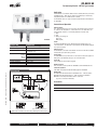
Multi-Function Technology®
Operation
All MFT actuators have built-in
brushless DC motors which provide better
accuracy and longer service life.
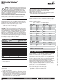
Control Accuracy and Stability
(AF / NF / LF / TF)
Control Accuracy and Stability
(GM / AM / NM / LM / AH / LH / LU / GR / AR / LR)
The …MFT US actuators are designed with a unique non-symmetrical
deadband. The actuator follows an increasing or decreasing control
signal with a 80 mV resolution. If the signal changes in the opposite
direction, the actuator will not respond until the control signal changes by
200 mV. This allows these actuators to track even the slightest deviation
very accurately, yet allowing the actuator to “wait” for a much larger
change in control signal due to control signal instability.
Belimo non-spring return actuators are designed with a unique nonsymmetrical deadband. The actuator follows an increasing or decreasing
control signal with a 75 mV resolution. If the signal changes in the
opposite direction, the actuator will not respond until the control signal
changes by 175 mV. This allows these actuators to track even the
slightest deviation very accurately, yet allowing the actuator to “wait” for a
much larger change in control signal due to control signal instability.
Actuator responds to a 75 mV signal when
not changing direction from stop position.
Satisfied
Control Position
Minimum
Control Resolution
Actuator responds to a 175 mV signal when
reversing direction from stop position.
Minimum Reversed
Control Deadband
Prior to Normal Control
175 mV
Satisfied
Control Position
800-543-9038 USA
10
866-805-7089 CANADA
203-791-8396 LATIN AMERICA
M40035 - 05/10 - Subject to change. © Belimo Aircontrols (USA), Inc.
75 mV
Multi-Function Technology®
Operation
All Belimo actuators have built-in
brushless DC motors which provide better
accuracy and longer service life.
Control Accuracy and Stability
(AMQ / NMQ / LMQ / AHQ / LHQ)
Belimo Quick Running non-spring return actuators are designed with a
unique non-symmetrical deadband. The actuator follows an increasing or
decreasing control signal with a 40 mV resolution. If the signal changes
in the opposite direction, the actuator will not respond until the control
signal changes by 100 mV. This allows these actuators to track even the
slightest deviation very accurately, yet allowing the actuator to “wait” for a
much larger change in control signal due to control signal instability.
Actuator responds to a 40 mV signal when
not changing direction from stop position.
Satisfied
Control Position
M40035 - 05/10 - Subject to change. © Belimo Aircontrols (USA), Inc.
40 mV
Minimum
Control Resolution
Actuator responds to a 100 mV signal when
reversing direction from stop position.
Minimum Reversed
Control Deadband
Prior to Normal Control
100 mV
Satisfied
Control Position
800-543-9038 USA
866-805-7089 CANADA
203-791-8396 LATIN AMERICA
11
Multi-Function Technology®
Operation
Running Time
Motion
Parameter Variables
Description
New Generation AF
70 to 220 seconds
New Generation NF
40 to 220 seconds
AF / NF / LF / TF
75 to 300 seconds
GM
75 to 300 seconds
Running time is selectable allowing for customizing the actuator for the
application at hand. Adjustable running time allows for:
• Matching HVAC system sequence of operation.
• Improving control loop stability.
• Reducing actuating noise (slower running).
• Retrofit applications
AM*
90 to 350 seconds
The running time is constant and independent of load.
NM*
45 to 150 seconds
AH*
75 to 150 seconds
LM*
35 to 150 seconds
LH*
75 to 150 seconds
LU
75 to 150 seconds
Direction of Rotation
Default or Reversed
The direction of rotation can be "Direct" or "Reverse" acting of the control
signal. The direction of rotation is selected from a CW and CCW switch
located on the actuator.
An alternative method of changing the direction of rotation is to use the
PC-Tool software. This option allows you to make remote set-up corrections
without having the need to be at the actuator.
Intermediate
Position
Control
(Override Control)
• Minimum Position (Default 0%)
• Intermediate Position (Default 50%)
• Maximum Position (Default 100%)
Intermediate Positions are achieved
through ‘forced override’ positions.
SEE FIGURE A – FORCED OVERRIDES.
All intermediate settings are adjustable from 0 to 100%. Programmed as
default, these control positions are possible by using the wiring diagram in
FIGURE A. The override functions can be used as a means to test the
actuator’s functionality during equipment servicing or troubleshooting.
Intermediate positions can also be integrated into the control circuit as a
part of the sequence of operation.
The Min, Mid, and Max positions can be used in any MFT control mode.
• VDC: For stand-alone controllers where a minimum position is needed.
• PWM: Eliminate add-on accessories.
• Floating Point: New functionality to a common application.
• On/Off: New functionality to a common application.
– Satisfy combustion air requirements or boiler sequencing with O/A damper.
– Eliminates secondary minimum position dampers.
* Quicker running actuators are available. Contact Belimo Customer Service for details.
FIGURE A – Forced Overrides
800-543-9038 USA
12
866-805-7089 CANADA
203-791-8396 LATIN AMERICA
M40035 - 05/10 - Subject to change. © Belimo Aircontrols (USA), Inc.
Rotation
Selection of the direction of rotation is only possible via the PC-Tool
software or manually with the switch on the actuator. Selection via a preset
configuration is not an option.
Multi-Function Technology®
Operation
Motion
Parameter Variables
Description
Adaptation
OFF
When the manual override button is depressed, and released, the actuator
will perform synchronization. The actuator will simply drive to the mechanical
zero position and return to its last control position.
ON – Manual
The default setting for adaptation is “ON – Manual”.
When the ON-Manual setting is selected, adaptation is initiated by:
•Pressing the manual override button once (GM / AM / NM / LM).
• Clicking the CW/CCW switch twice (AF, NF, LF and TF).
M40035 - 05/10 - Subject to change. © Belimo Aircontrols (USA), Inc.
Mechanical Relationship
When adaptation is selected, (On-Manual or Automatic) the actuator will drive
one full cycle to its mechanical end stops OR the valves mechanical seats.
Upon completion of this cycle the actuators working range (input, feedback and
running time) will be adapted to the actual mechanical angle of rotation.
ON – Automatic
When the ON-Automatic setting is selected at every power-up the actuator
will automatically adapt to the mechanical angle of rotation. Also upon
pressing the manual override button or CW/CCW switch, adaptation is
initiated (See above).
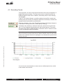
Sound and
Running Time
All Actuators
As the speed of the actuator increases, there is an increase in the sound
power level.
Torque and
Running Time
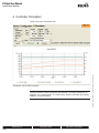
Original Spring Return (AF / NF / LF)
Though the running time remains constant, at approximately the 100-second
range there is a loss in output torque. This is due to the association of
runtime to torque. To gain a faster running time there is a loss in torque.
SEE FIGURE B.
FIGURE B – Torque and Run Time
Torque and Run Time, LF24-MFT US
TORQUE [in-lb]
35
100 % torque
r curve
26
75
100
150
Running time [s]
NOTE: All new generation spring return and non-spring return actuators are torque independent of speed.
800-543-9038 USA
866-805-7089 CANADA
203-791-8396 LATIN AMERICA
13
Multi-Function Technology®
Specifications/Descriptions
Specifications
Parameter Variables
Description
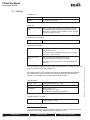
Alarms - Fault
A fixed voltage of 8.5 VDC is present when
Alarm ‘sounds’.
Hunting
Alarm criteria: Actuator is hunting due to unstable control loop.
This fault occurs when the ratio of Active time to Operating time exceeds
20%.
Operating time: Total number of hours connected to power supply Active
time: Total number of hours the actuator is in mechanical motion.
Alarm - Maintenance
A fixed voltage of 5.5 VDC is present when
Alarm ‘sounds’.
Mechanical Overload
Alarm criteria: Actuator is in a position and not responding to the control
input. An alarm will ‘sound’ when an object or circumstance is preventing
the motion of the actuator, damper or valve. The actuator has initiated its
own overload protection after a period of 13 seconds.
Mechanical Travel
Alarm criteria: Actuator is adapted to the working angle of a damper or
to the stroke of a valve and is less than 95-degree actuator rotation (eg.
75° adapted angle). An alarm will ‘sound’ when the actuator detects a
mechanical travel difference of 10% above the adapted angle (eg. 82.6°).
Mechanical load limit
(Non-Sprlng Return Only)
Alarm criteria: The torque load of the application has exceeded the
actuator’s torque.
A typical scenario – the torque requirements has increased due to:
• Lack of lubrication
• Increased flow
• Improper installation
• Damage
• Dirt and debris build-up
M40035 - 05/10 - Subject to change. © Belimo Aircontrols (USA), Inc.
The alarm ‘sounds’ when the specified torque rating of the actuator has
been exceeded for a period of 5 seconds.
800-543-9038 USA
14
866-805-7089 CANADA
203-791-8396 LATIN AMERICA
Multi-Function Technology®
Specifications/Definitions
Parameter Variables
Identification
Serial Number
Displays the actuators internal serial number.
Actuator Type / Software Version
Displays the actuator nomenclature (AFX24-MFT US) and MFT software version.
Assembly Location
Displays the where the actuator was assembled.
Setpoint
Displays the actual control input position as a percentage. As signal input
changes you will see the setpoint percentage change accordingly.
Actual Values
Actual Position
Displays the actual position as a percentage. As the setpoint changes the
actual position percentage will increase or decrease accordingly. If the
actuator is capable of rotating the damper or valve, this can be of benefit
when troubleshooting an application.
Function
Control Type & Setting
Displays the actual control type and operating range.
Displays
Service
Data Log
Feedback Type & Setting
Displays the actual feedback signal type and operating range.
Torque % Setting
Displays the actual torque setting, as a percentage of minimum torque.
Running Time
Displays the actual running time as programmed in seconds.
Direction of Rotation
Displays the status of the direction of rotation option (Normal or Reversed).
Min, Mid, Max Position
Displays the actual position setting of the Intermediate position control.
Adaptation
Displays the actual setting of the adaptation function (OFF, ON-Manual, ONAutomatic).
Sensitivity / Hysteresis
Displays the actual setting of the sensitivity (Normal or Reduced).
Synchronization
Displays the actual setting of the synchronization function (Normal, Sync at
0%, Sync at 100%).
Total Time / Operating Time
Total number of hours the actuator is connected to a power supply.
Active Time
Total number of hours the actuator is in motion.
Stop / Go Ratio (Hunting %)
Displays a percentage the total number of hours the actuator has spent in
mechanical motion, comparing the total time to the active time.
Normal, Reduced
Displays the setting of the sensitivity function.
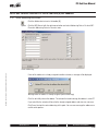
Messages
Displays all messages present. Messages can be deleted as well.
Function Test
This function enables you to check for complete opening and closing of the
actuator.
The test report contains:
• Information on the Project
• Identification on the Actuator
• A list of fault messages pending before the start of the test
• The test steps and results
• The current actuator settings
Functions
M40035 - 05/10 - Subject to change. © Belimo Aircontrols (USA), Inc.
Sensitivity
Description
This is of benefit when troubleshooting an application, as the actuator
will drive the damper or valve. This gives an opportunity to observe the
installation to identify any possible problems.
Adaptation
See Adaptation on page 13.
Initiates the adaptation feature of the MFT actuator. The actuators working
range (input, feedback, and running time) will be adapted to the actual angle
of rotation.
This is of benefit when troubleshooting an application, as the actuator will
drive the damper or valve. This gives you an opportunity to observe the
installation to identify any possible problems.
Synchronization
800-543-9038 USA
Normal
At initial commissioning, when the manual override button is pressed, the
actuator runs to a default position defined by the position of the CW/CCW
direction of rotation switch.
Sync at 0%
At each power-up (includes power failures), the actuator runs to a default
position defined by the position of the CW/CCW direction of rotation switch.
Sync at 100%
At each power-up (includes power failures), the actuator runs to a default
position of the CW/CCW direction of rotation switch.
866-805-7089 CANADA
203-791-8396 LATIN AMERICA
15
Multi-Function Technology®
Wiring
WARNING The wiring technician must be trained and experienced
with electronic circuits. Disconnect power supply before attempting
any wiring connections or changes. Make all connections in
accordance with wiring diagrams and follow all applicable local and national
codes. Provide disconnect and overload protection as required. Use copper,
twisted pair, conductors only. If using electrical conduit, the attachment to the
actuator must be made with flexible conduit.
Always read the controller manufacturer's installation literature carefully
before making any connections. Follow all instructions in this literature. If you
have any questions, contact the controller manufacturer and/or Belimo.
Multiple actuators positioned by the same control signal may be powered from
multiple transformers provided the following rules are followed:
1. The transformers are properly sized.
2. All No. 1 wires from all actuators are tied together and tied to the negative leg
of the control signal. See wiring diagram on page 11.
Wire Lengths for Actuators
Keep power wire runs below the lengths listed in the Figure H. If more than one
actuator is powered from the same wire run, divide the allowable wire length by
the number of actuators to determine the maximum run to any single actuator.
Non-spring return actuators require a 24 VAC class 2 transformer and draws a
maximum of 5 VA per actuator. The actuator enclosure cannot be opened in the
field, there are no parts or components to be replaced or repaired.
– EMC directive: 89/336/EEC
– Software class A: Mode of operation type 1
– Low voltage directive: 73/23/EEC
CAUTION: It is good practice to power electronic or digital controllers from a
separate power transformer than that used for actuators or other end devices.
The power supply design in our actuators and other end devices use half wave
rectification. Some controllers use full wave rectification. When these two
different types of power supplies are connected to the same power transformer
and the DC commons are connected together, a short circuit is created across
one of the diodes in the full wave power supply, damaging the controller. Only
use a single power transformer to power the controller and actuator if you know
the controller power supply uses half wave rectification.
Typical Transformer Sizing
Actuator Series
Voltage
New Generation AF 24
Original AF
24
New Generation NF 24
Original NF
24
LF
24
TF
24
GMB/GRB
24
AMB/ARB
24
NMB
24
LMB/LRB
24
AHB
24
LHB
24
LUB
24
AMQB
24
NMQB
24
LMQB
24
AHQB
24
LHQB
24
* @ 70 second run time
** @ 40 second run time
Required VA Per Actuator
10*
10
9**
6
6
4
7
6
6
5
6
5
5
18
18
18
18
18
Multiple Actuators, One Transformer
Multiple actuators may be powered from one transformer provided the following
rules are followed:
1. The TOTAL current draw of the actuators (VA rating) is less than or equal to
the rating of the transformer.
2. Polarity on the secondary of the transformer is strictly followed. This means
that all No. 1 wires from all actuators are connected to the common leg on
the transformer and all No. 2 wires from all actuators are connected to the
hotleg. Switching wire No. 1 & 2 on one leg of the transformer will result in
erratic operation or failure of the actuator and/or controls.
800-543-9038 USA
Example: 3 actuators, 16 Ga wire
350 Ft ÷ 3 Actuators = 117 Ft. Maximum wire run
LH-24…/LU-24…
LM-24.../CM24
Wire Size
16 Ga
18 Ga
20 Ga
22 Ga
Wire Size
16 Ga
18 Ga
20 Ga
22 Ga
Max. Feet.
1175 Ft.
1075 Ft.
575 Ft.
300 Ft.
Max. Feet
1125 Ft.
750 Ft.
400 Ft.
200 Ft.
NM-24…/AH-24…/LMX120…
AM-24...
Wire Size
12 Ga
14 Ga
16 Ga
18 Ga
20 Ga
22 Ga
Wire Size
12 Ga
12 Ga
16 Ga
18 Ga
20 Ga
22 Ga
Max. Feet
1150 Ft.
925 Ft.
550 Ft.
375 Ft.
200 Ft.
100 Ft.
Wire Size
18 Ga
20 Ga
22 Ga
Max. Feet
325 Ft.
175 Ft.
90 Ft.
Max. Feet.
1250 Ft.
1130 Ft.
900 Ft.
575 Ft.
300 Ft.
150 Ft.
GM…/NMX120…/AMX120…
Wire Size
12 Ga
14 Ga
16 Ga
Max. Feet.
1125 Ft.
800 Ft.
500 Ft.
FIGURE H – Maximum Wire Lengths
Wire Type and Wire Installation Tips
For most installations, 18 or 16 Ga. cable works well with the non-spring return
actuators. Use code-approved wire nuts, terminal strips or solderless
connectors where wires are joined. It is good practice to run control wires
unspliced from the actuator to the controller. If splices are unavoidable, make
sure the splice can be reached for possible maintenance. Tape and/or wire-tie
the splice to reduce the possibility of the splice being inadvertently pulled apart.
The non-spring return proportional actuators have a digital circuit that is
designed to ignore most unwanted input signals (pickup). In some situations the
pickup may be severe enough to cause erratic running of the actuator. For
example, a large inductive load (high voltage AC wires, motors, etc.) running
near the power or control wiring may cause excessive pickup. To solve this
problem, make one or more of the following changes:
1. Run the wire in metallic conduit.
2. Re-route the wiring away from the source of pickup.
3. Use shielded wire (Belden 8760 or equal). Ground the shield to an earth
ground. Do not connect it to the actuator common.
866-805-7089 CANADA
203-791-8396 LATIN AMERICA
M40035 - 05/10 - Subject to change. © Belimo Aircontrols (USA), Inc.
Transformer(s)
16
Multiple Actuators, Multiple Transformers
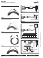
Multi-Function Technology®
Wiring
W048_08
ATTENTION
Master-Slave is the correct method for wiring multiple Belimo MFT actuators to
a single load. For example, you can have up to three AFX24-MFT on a single
damper jackshaft or two GMX24-MFT on a large butterfly valve.
The current Belimo solution is to mount multiple actuators onto the damper or
valve. In the past this required the installer to wire the actuators in a “masterslave” arrangement. This was typical for the AF24-SR US actuator.
By adding more actuators you can effectively increase the torque proportional to
the minimum specified torque times the number of actuators. This is normal as
seen on the following installations.
• Large dampers or valves
• Large multiple section dampers
• Rack and Pinion style globe valves
• Ball or Butterfly valves
Multiple actuators mounted to one control shaft
Model
AFX24-MFT(-S)
NFX24-MFT(-S)
LF24-MFT(-S) US
GMX24-MFT
AMX24-MFT
NMX24-MFT
LMX24-MFT
GKX24-MFT
Max. Qty Per Shaft
3
1
1
2
1
1
1
2
Torque Generated
432 in-lb
90 in-lb
35 in-lb
640 in-lb
180 in-lb
90 in-lb
45 in-lb
720 in-lb
#
The wiring method for multiple actuators mounted to shafts which are not
mechanically connecting other actuators is to wire the control signal in parallel
with each actuator.
Wiring multiple …MFT actuators to one shaft.
All MFT actuators are wired in master-slave configuration.
EXCEPTION No mechanical dual mounting of AFX24-MFT US is possible.
Electrical parallel wiring of AFX24-MFT95 is possible only for
mechanically separate applications.
M40035 - 05/10 - Subject to change. © Belimo Aircontrols (USA), Inc.
SOLUTION
For increased torque requirement use AFX24-MFT95 as a master
and the slave must be an AFX24-MFT. The masters feedback must
match the slaves input signal. (Both are default 2-10 VDC.)
Wiring of multiple …MFT actuators on valves must be master-slave (wires 3-5).
MFT actuator configurations should also co-ordinate with each other.
Meaning the master input = controllers output. Master output = slave input.
Slave output = controller input.
W214_08
Multiple XM24-MFT95…
Wiring Diagrams
1
2
Provide overload protection and disconnect as required.
CAUTION Equipment damage!
Actuators may be connected in parallel if not mechanically mounted to the
same shaft. Power consumption and input impedance must be observed.
3
Actuators may also be powered by 24 VDC.
5
Control signal may be pulsed from either the Hot (source)
or the Common (sink) 24 VAC line.
The ZG-R01 500 Ω resistor may be used.
WARNING Live Electrical Components!
During installation, testing, servicing and troubleshooting of this product, it may
be necessary to work with live electrical components. Have a qualified licensed electrician
or other individual who has been properly trained in handling live electrical components
perform these tasks. Failure to follow all electrical safety precautions when exposed to live
electrical components could result in death or serious injury.
Controller Output
0.1 to 25.5 sec
800-543-9038 USA
866-805-7089 CANADA
Master Feedback
2 to 10 VDC
Slave Input
2 to 10 VDC
Slave Feedback
0 to 5 VDC
203-791-8396 LATIN AMERICA
17
Multi-Function Technology®
Wiring Diagrams
Spring Return Actuator with MFT
VDC / 4 to 20mA
Two Position
PWM
Original AF, NF, LF, TF
New Generation AF, NF
Floating Point
Override control to min, mid, max positions
W425_08
VDC / 4 to 20mA
Two Position
Floating Point
Override control to min, mid, max positions
800-543-9038 USA
18
M40035 - 05/10 - Subject to change. © Belimo Aircontrols (USA), Inc.
Non-Spring Return Actuator with MFT
PWM
866-805-7089 CANADA
W426_08
203-791-8396 LATIN AMERICA
Multi-Function Technology®
Wiring Diagrams
0 to 135 Ω Control (MFT95)
Wiring multiple actuators to a Series 90
controller
M40035 - 05/10 - Subject to change. © Belimo Aircontrols (USA), Inc.
Override
Low Limit Control
Wiring multiple actuators to a Series
90 controller using a minimum position
potentiometer
High Limit Control
Typical wiring diagrams for multiple
actuators used with the W973, W7100 and
T775 controllers.
AF24-MFT95 US Wire Colors
1=Black
3=White
5=White
2=Red
4=White
6=White
AFX24-MFT95 and Non-Spring Return Wire Colors
1=Black
3=White
5=Gray
2=Red
4=Pink
6=Orange
800-543-9038 USA
866-805-7089 CANADA
203-791-8396 LATIN AMERICA
19
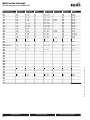
Multi-Function Technology®
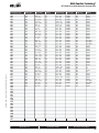
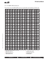
MFT VDC Proportional Control Program Codes
Programmable Code
A01
A02
A03
A04
A05
A06
A07
A08
A09
A10
A11
A12
A13
A14
A15
A16
A17
A18
A19
A20
A21
A22
A23
A24
A25
A26
A27
A28 PICCV ONLY
A29
A30
A31
A32
A33
A34
A35
A37
A38
A39
A40
A41
A42
A43
A44
A45
A46
A47
A48
A49
A51
A52
A53
A54
A55
A56
A57
A58
A59
A60
A61
A62
A63
A64
A65
Running Time
150s
150s
150s
150s
150s
150s
150s
150s
150s
150s
150s
150s
150s
100s
150s
150s
150s
150s
100s
150s
150s
150s
150s
150s
76s
150s
150s
100s
150s
150s
150s
150s
150s
120s
78s
120s
150s
150s
150s
150s
75s
150s
150s
150s
150s
150s
150s
150s
Control Range
2...10V
0.5...10V
2...10V
4...7V
6...9V
10.5...13.5V
0.5...5V
0.5...5V
5...10V
5...10V
0.5...5V
0.5...5V
0.5...10V
0.5…10V
2…5V
2…6V
6…10V
14…17V
2...10V
9...12V
2…10V
0.5…4.9V
5.1…10V
0.5…24V
2...10V
2…9V
5…9V
0.5...10V
1…3V
3…9V
0.5…4V
6…14V
4…14V
2...10V
2...10V
0.5...10V
6...13V
10...14V
1...16V
3...6V
0.5…10V
0.5…2.5V
7…10V
13...17V
2...10V
0.5…20V
1…5V
1…5V
Feedback
U5
U5
U5
U5
U5
U5
U5
U5
U5
U5
U5
U5
U5
U5
U5
U5
U5
U5
U5
U5
U5
U5
U5
U5
U5
U5
U5
U5
U5
U5
U5
U5
U5
U5
U5
U5
U5
U5
U5
U5
U5
U5
U5
U5
U5
U5
U5
U5
Feedback Range
U5 2...10V
U5 0.5…10V
U5 0.5…5V
U5 2…10V
U5 2…10V
U5 2…10V
U5 2…10V
U5 0.5…10V
U5 2…10V
U5 0.5…10V
U5 0.5…5V
U5 0.5…2.5V
U5 2…10V
U5 0.5…2.5V
U5 2…10V
U5 2…10V
U5 2…10V
U5 2…10V
U5 2...10V
U5 2...10V
U5 0.5…5V
0.5…4.9V
5.1…10V
U5 2...10V
U5 2...10V
U5 2...10V
U5 2...10V
U5 0.5…10V
U5 2...10V
U5 2...10V
U5 2...10V
U5 2...10V
U5 2...10V
U5 2...10V
U5 2...10V
U5 0.5…10V
U5 2...10V
U5 2...10V
U5 2...10V
U5 2...10V
U5 2...10V
U5 2...10V
U5 2...10V
U5 2...10V
U5 2...10V
U5 2...10V
U5 1…5V
U5 1…5V
150s
120s
150s
75s
75s
150s
150s
150s
300s
150s
90s
150s
150s
150s
2...10V
0.5…10V
0.5…2.5V
2…5V
6…9V
2…5.5V
6.5…10V
0.5…6V
2…10V
10…20V
2…10V
0.5…4.5V
5.5…10V
1…5V
U5
U5
U5
U5
U5
U5
U5
U5
U5
U5
U5
U5
U5
U5
U5 0.5…5V
U5 2...10V
U5 0.5…2.5V
U5 2...10V
U5 2...10V
U5 2...10V
U5 2...10V
U5 2...10V
U5 2...10V
U5 2...10V
U5 2...10V
U5 0.5…4.5V
U5 5.5…10V
U5 1…5V
800-543-9038 USA
20
866-805-7089 CANADA
Obsolete Code
P-10001
P-10002
P-10003
P-10004
P-10005
P-10006
P-10007
P-10008
P-10009
P-10010
P-10011
P-10012
P-10013
P-10014
P-10015
P-10016
P-10017
P-10018
P-10019
P-10020
P-10021
P-10022
P-10023
P-10024
P-10025
P-10026
P-10027
P-10028
P-10029
P-10030
P-10031
P-10032
P-10033
P-10034
P-10035
P-10037
P-10038
P-10039
P-10040
P-10041
P-10042
P-10043
P-10044
P-10045
P-10046
P-10047
P-10048
P-10049
P-10051
P-10052
P-10053
P-10054
P-10055
P-10056
P-10057
P-10058
P-10059
P-10060
P-10061
P-10062
P-10063
P-10064
P-10065
MP Bus Logo
NO
NO
NO
NO
NO
NO
NO
NO
NO
NO
NO
NO
NO
NO
NO
NO
NO
NO
NO
NO
NO
NO
NO
NO
NO
NO
NO
NO
NO
NO
NO
NO
NO
NO
NO
NO
NO
NO
NO
NO
NO
NO
NO
NO
NO
NO
NO
NO
Adaption
manual
manual
manual
manual
manual
manual
manual
manual
manual
manual
manual
manual
manual
manual
manual
manual
manual
manual
manual
manual
manual
manual
manual
manual
manual
manual
manual
manual
manual
manual
manual
manual
manual
manual
manual
manual
manual
manual
manual
manual
manual
manual
manual
manual
manual
manual
auto-adapt.
auto-adapt.
NO
NO
NO
NO
NO
NO
NO
NO
NO
NO
NO
NO
NO
NO
manual
manual
manual
manual
manual
manual
manual
manual
manual
manual
manual
manual
manual
manual
203-791-8396 LATIN AMERICA
M40035 - 05/10 - Subject to change. © Belimo Aircontrols (USA), Inc.
*Note: Not every code works with every acuator
Multi-Function Technology®
M40035 - 05/10 - Subject to change. © Belimo Aircontrols (USA), Inc.
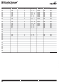
MFT VDC Proportional Control Program Codes
Programmable Code
A66
A67
A68
A69
A70
A71
A72
A73
A74
A76
A77
A78
A79
A80
A81
A82
A83
A84
A85
A86
A88
A89
A90
A91
A92
A93
A94
A95
A96
A97
A98
A99
AA0
AA1
AA2
AA4
AA5
AA6
AA7
AA8
AA9
AAA
AAB
AAC
AAD
AAE
AAF
AAG
AAH
AAJ
AAK
AAL
AAM
AAN
AAP
AAR
AAS
AAT
AAU
AAV
AAW
AAX
AC0
Running Time
150s
150s
150s
150s
150s
150s
95s
150s
150s
150s
76s
150s
150s
150s
150s
150s
150s
150s
150s
150s
150s
150s
150s
95s
150s
150s
85s
150s
150s
150s
150s
150s
150s
150s
150s
150s
150s
150s
150s
150s
Control Range
2…10V
2…8V
2…13V
1..4V
3.5…10V
2…15V
2…10V
6…18V
2…10V
0.5…3V
0.5…10V
2…10V
0.5…10V
0.5…3.5
4.5…10
3…10V
5…15V
13…20V
2…10V
5…10.5
2…10V
12.5…22V
2…5V
2…10V
0.5…15V
2…10V
2…10V
0.5…5V
0.5…10V
5.25…7.25
2…10V
2…10V
0.5…12.85
3…15V
0.5…14V
0.5…22V
0.5…4V
6…10V
2…7V
4…10V
Feedback
U5
U5
U5
U5
U5
U5
U5
U5
U5
U5
U5
U5
U5
U5
U5
U5
U5
U5
U5
U5
U5
U5
U5
U5
U5
U5
U5
U5
U5
U5
U5
U5
U5
U5
U5
U5
U5
U5
U5
Feedback Range
U5 1…5V
U5 2…10V
U5 2…10V
U5 2…10V
U5 2…10V
U5 2…10V
U5 2…10V
U5 2…10V
U5 2…10V
U5 0.5…10V
U5 0.5…10V
U5 0.5…10V
U5 0.5…5V
U5 2…10V
U5 2…10V
U5 2…10V
U5 2…10V
U5 2…10V
U5 2…10V
U5 2…10V
U5 2…10V
U5 2…10V
U5 2…5V
U5 2…10V
U5 0.5…10V
U5 2…10V
U5 2…10V
U5 0.5…5V
U5 2…10V
U5 2…10V
U5 2…10V
U5 2…10V
U5 2…10V
U5 2…10V
U5 2…10V
U5 2…10V
U5 0.5…5V
U5 0.5…5V
U5 2…10V
U5 2…10V
150s
150s
150s
100s
100s
150s
75s
150s
100s
100s
150s
120s
100s
150s
150s
150s
20s
100s
150s
2…22V
0.5…20V
0.5….29V
0.5…4.5V
5.5…10V
0.5…28V
0.5…10V
0.5…10V
2…6V
6…10V
8…20V
0.5…10V
0.5…10V
2…10V
2…10V
2…10V
2…10V
6…9V
1.2…6V
U5
U5
U5
U5
U5
U5
U5
U5
U5
U5
U5
U5
U5
U5
U5
U5
U5
U5
U5
35s
45s
2…10V
2…10V
U5
U5
800-543-9038 USA
MP Bus Logo
NO
NO
NO
NO
NO
NO
NO
NO
NO
NO
NO
NO
NO
NO
NO
NO
NO
NO
NO
NO
NO
NO
NO
NO
NO
NO
NO
NO
NO
NO
NO
NO
NO
NO
NO
NO
NO
NO
NO
NO
Adaption
manual
manual
manual
manual
manual
manual
manual
manual
manual
manual
manual
manual
manual
manual
manual
manual
manual
manual
manual
manual
manual
manual
manual
manual
manual
manual
manual
manual
manual
manual
auto-synch.
manual
manual
manual
manual
manual
manual
manual
manual
manual
U5 2…10V
U5 0.5…10V
U5 2…10V
U5 0.5…4.5V
U5 5.5…10V
U5 2…10V
U5 2…10V
U5 4…5V
U5 2…10V
U5 2…10V
U5 2…10V
U5 2…10V
U5 2…10V
U5 2…10V
U5 2…10V
U5 2…10V
U5 2…10V
U5 2…10V
U5 2…10V
Obsolete Code
P-10066
P-10067
P-10068
P-10069
P-10070
P-10071
P-10072
P-10073
P-10074
P-10076
P-10077
P-10078
P-10079
P-10080
P-10081
P-10082
P-10083
P-10084
P-10085
P-10086
P-10088
P-10089
P-10090
P-10091
P-10092
P-10093
P-10094
P-10095
P-10096
P-10097
P-10098
P-10099
P-10100
P-10101
P-10102
P-10104
P-10105
P-10106
P-10107
P-10108
P-10109
P-10110
P-10111
P-10112
P-10113
P-10114
P-10115
P-10116
P-10117
P-10118
P-10119
P-10120
P-10121
P-10122
P-10123
P-10124
P-10125
-------
NO
NO
NO
NO
NO
NO
NO
NO
NO
NO
NO
NO
NO
NO
NO
NO
NO
NO
NO
manual
manual
manual
manual
manual
manual
auto-adapt.
auto-adapt.
auto-adapt.
manual
manual
auto-synch.
manual
manual
auto-adapt.
manual
manual
manual
manual
U5 2...10V
U5 2...10V
P-10130
P-10131
NO
NO
manual
manual
866-805-7089 CANADA
203-791-8396 LATIN AMERICA
21
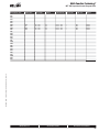
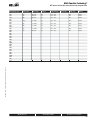
Multi-Function Technology®
Programmable Code
AC1
AC2
000
AC4
AC5
AC6
AC7
AC8
AC9
ACA
ACX
AD0
AD1
AD2
AD3
AD4
AD5
AD6
AD7
AD8
AD9
ADA PICCV ONLY
ADC
ADD
ADE
ADF
ADG
ADH
ADJ
ADK
ADL
ADM
ADN
ADP
ADR
ADS
ADT
ADU
ADV
ADW
ADX
AE0
AE1
AE2
AE3
Running Time
90s
150s
150s
150s
75s
450s
150s
35s
45s
90s
150s
100s
100s
90s
35s
150s
100s
Control Range
2…10V
0.5…10V
2…10V
0.5…10V
2…10V
2…10V
…
0.5…10V
0.5…10V
0.5…10V
2...10V
0.5...5V
5…10V
2…10V
2…10V
2…10V
2...5V
Feedback
U5
U5
U5
U5
U5
U5
U5
U5
U5
U5
U5
U5
U5
U5
U5
U5
U5
Feedback Range
U5 2...10V
U5 0.5…10V
U5 2...10V
U5 0.5…10V
U5 2…10V
U5 2…10V
U5 2...10V
U5 0.5...10V
U5 0.5...10V
U5 0.5...10V
U5 0.5...10V
U5 2...10V
U5 2...10V
U5 2...10V
U5 2...10V
U5 2...10V
U5 2...10V
Obsolete Code
P-10132
------P-10133
P-10134
---------
100s
0.5...5V
U5
100s
0.5...10V
150s
70s
40s
800-543-9038 USA
22
P-10135
P-10136
------P-10137
MP Bus Logo
NO
NO
YES
YES
NO
NO
NO
NO
NO
NO
NO
NO
NO
NO
NO
NO
NO
Adaption
manual
manual
manual
manual
manual
manual
manual
manual
manual
manual
manual
manual
manual
auto-adapt.
auto-adapt.
manual
manual
U5 2...10V
P-10140
NO
manual
U5
U5 0.5…10V
---
NO
manual
9…13V
U5
U5 2...10V
---
NO
manual
2...10V
2...10V
US
US
US 2...10V
US 2...10V
-----
NO
NO
manual
manual
866-805-7089 CANADA
203-791-8396 LATIN AMERICA
M40035 - 05/10 - Subject to change. © Belimo Aircontrols (USA), Inc.
MFT VDC Proportional Control Program Codes
Multi-Function Technology®
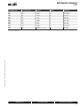
MFT VDC Proportional Control Program Codes
Running Time
Control Range
Feedback
Feedback Range
Obsolete Code
MP Bus Logo
Adaption
120s
75s
300s
450s
0.5…10V
0.5…10V
0.5…10V
0.5…10V
U5
U5
U5
U5
U5 0.5…10V
U5 0.5…10V
U5 0.5…10V
U5 0.5…10V
---------
NO
NO
NO
NO
manual
manual
manual
manual
M40035 - 05/10 - Subject to change. © Belimo Aircontrols (USA), Inc.
Programmable Code
AE4
AE5
AE6
AE7
AE8
AE9
AEA
AEC
AED
AEE
AEF
AEG
AEH
AEJ
AEK
AEL
AEM
AEN
AEP
AER
AES
AET
AEU
AEV
AEW
AEX
AF0
800-543-9038 USA
866-805-7089 CANADA
203-791-8396 LATIN AMERICA
23
Multi-Function Technology®
MFT 95 (Honeywell Series 90, 0-135Ω) Program Codes
Running Time
150s
150s
150s
75s
100s
Control Range
0…135 Ohm
0…135 Ohm
0…135 Ohm
0…135 Ohm
0…135 Ohm
Feedback
U5
U5
U5
U5
U5
Feedback Range
U5 2…10V
U5 0.5…10V
U5 0.5…5V
U5 2…10V
U5 0.5…10V
35s
45s
90s
37s
0…135 Ohm
0…135 Ohm
0…135 Ohm
0…135 Ohm
U5
U5
U5
U5
U5 2…10V
U5 2…10V
U5 2…10V
U5 2…10V
Obsolete Code
P-16001
P-16002
P-16003
P-16004
P-16028
P-16029
MP Bus Logo
NO
NO
NO
NO
NO
Adaption
manual
manual
manual
manual
manual
NO
NO
NO
NO
manual
manual
manual
manual
M40035 - 05/10 - Subject to change. © Belimo Aircontrols (USA), Inc.
Programmable Code
R01
R02
R03
R04
R05
R06
R07
R08
R09
R0A
R0C
R0D
R0E
R0F
R0G
R0H
R0J
R0K
R0L
R0M
R0N
R0P
R0R
R0S
R0T
R0U
R0V
R0W
R0X
R10
R11
800-543-9038 USA
24
866-805-7089 CANADA
203-791-8396 LATIN AMERICA
Multi-Function Technology®
M40035 - 05/10 - Subject to change. © Belimo Aircontrols (USA), Inc.
MFT PWM (Pulse Width Modulation) Program Codes
Programmable Code
W01
W02
W03
W04
W05
W06
W07
W08
W09
W10
W11
W12
W13
W14
W15
W16
W17
W18
W19
W20
W21
W22
W23
W24
W25
W26
W27
W28
W29
W30
W31
W32
W33
W34
W35
W36
W37
W38
W39
W3A
W3C
W3D
W3E
W3F
W3G
W3H
W3J
W3K
W3L
W3M
W3N
W3P
W3R
W3S
W3T
W3U
W3V
W3W
W3X
W40
W41
Running Time
150s
150s
150s
150s
150s
150s
150s
150s
150s
150s
150s
150s
150s
150s
150s
150s
150s
150s
150s
150s
150s
150s
150s
150s
150s
150s
150s
150s
150s
150s
100s
100s
150s
100s
150s
150s
150s
150s
150s
150s
150s
150s
800-543-9038 USA
Control Range
0.59…2.93s
0.02…5s
0.1…25.5s
0.1…25.6s
0.1…5.2s
0.59…2.93s
0.02…5s
0.1…10s
1…11s
0.02…5s
0.02…5.6s
0.5…25.5s
0.5…2.93s
0.1…10s
1…11s
0.02…5s
0.02…5.6s
0.1…25.5s
0.02…2.5s
2.7…5s
0.1…5.2s
0.1…12.85s
5.1…10.1s
0.59…1.76s
1.76…2.93s
0.02…12s
0.02…14s
12.5…22s
0.5…12.85s
0.1…24s
0.02…5s
0.1…25.5
0.2…25.5
0.59…2.93s
5.5…9.5s
0.5…4.5s
0.1…5.2s
0.02…6s
0.59…2.93s
0.5…5.0s
0.1...25.5s
0.2...5.2s
Feedback
U5
U5
U5
U5
U5
U5
U5
U5
U5
U5
U5
U5
U5
U5
U5
U5
U5
U5
U5
U5
U5
U5
U5
U5
U5
U5
U5
U5
U5
U5
U5
U5
U5
U5
U5
U5
U5
U5
U5
U5
U5
U5
Feedback Range
U5 2…10V
U5 2…10V
U5 2…10V
U5 2…10V
U5 0.5…5V
U5 0.5…10V
U5 0.5…5V
U5 2…10V
U5 2…10V
U5 2…10V
U5 2…10V
U5 2…10V
U5 2…10V
U5 2…10V
U5 2…10V
U5 2…10V
U5 2…10V
U5 2…10V
U5 2…10V
U5 2…10V
U5 2…10V
U5 2…10V
U5 2…10V
U5 2…10V
U5 2…10V
U5 2…10V
U5 2…10V
U5 2…10V
U5 2…10V
U5 2…10V
U5 Ω2…10V
U5 2…10V
U5 2…10V
U5 2…10V
U5 2…10V
U5 2…10V
U5 0.5…10V
U5 2…10V
U5 2…10V
U5 2…10V
U5 2...10V
U5 2...10V
866-805-7089 CANADA
Obsolete Code
P-20001
P-20002
P-20003
P-20004
P-20005
P-20006
P-20007
P-20008
P-20009
P-20010
P-20011
P-20012
P-20013
P-20014
P-20015
P-20016
P-20017
P-20018
P-20019
P-20020
P-20021
P-20022
P-20023
P-20024
P-20025
P-20026
P-20027
P-20028
P-20029
P-20030
P-20031
P-20032
P-20033
P-20034
P-20035
P-20036
P-20037
P-20038
P-20039
P-20040
--P-20041
MP Bus Logo
NO
NO
NO
NO
NO
NO
NO
NO
NO
NO
NO
NO
NO
NO
NO
NO
NO
NO
NO
NO
NO
NO
NO
NO
NO
NO
NO
NO
NO
NO
NO
NO
NO
NO
NO
NO
NO
NO
NO
NO
NO
NO
Adaption
manual
manual
manual
manual
manual
manual
manual
manual
manual
manual
manual
manual
manual
manual
manual
auto-adapt.
auto-adapt.
auto-adapt.
manual
manual
manual
manual
manual
manual
manual
manual
manual
manual
manual
manual
off
off
manual
off
manual
manual
manual
manual
auto-adapt.
auto-adapt.
manual
manual
203-791-8396 LATIN AMERICA
25
Multi-Function Technology®
MFT Floating Point Program Codes
Running Time
150s
150s
100s
100s
100s
150s
300s
75s
85s
150s
75s
120s
90s
150s
150s
90s
60s
45s
35s
Control Range
---------------------------------------
Feedback
U5
U5
U5
U5
U5
U5
U5
U5
U5
U5
U5
U5
U5
U5
U5
U5
U5
U5
U5
Feedback Range
U5 2…10V
U5 0.5…10V
U5 2…10V
U5 0.5…5V
U5 0.5…10V
U5 0.5…5V
U5 2…10V
U5 2…10V
U5 2…10V
U5 0.5…6V
U5 0.5…5V
U5 0.5…10V
U5 2…10V
U5 0.5…4.5V
U5 1…5V
U5 1…10V
U5 2…10V
U5 2…10V
U5 2…10V
Obsolete Code
P-30001
P-30002
P-30003
P-30004
P-30005
P-30006
P-30007
P-30008
P-30009
P-30010
P-30011
P-30013
P-30014
P-30015
P-30016
P-30017
-------
MP Bus Logo
NO
NO
NO
NO
NO
NO
NO
NO
NO
NO
NO
NO
NO
NO
NO
NO
NO
NO
NO
Adaption
manual
manual
manual
manual
manual
manual
manual
manual
manual
manual
manual
manual
manual
manual
manual
manual
manual
manual
manual
120s
450s
-----
U5
U5
U5 2...10V
U5 2…10V
-----
NO
NO
manual
manual
800-543-9038 USA
26
M40035 - 05/10 - Subject to change. © Belimo Aircontrols (USA), Inc.
Programmable Code
F01
F02
F03
F04
F05
F06
F07
F08
F09
F10
F11
F13
F14
F15
F16
F17
F18
F19
F1A
F1C
F1D
F1E
F1F
F1G
F1H
F1J
F1K
F1L
F1M
F1N
F1P
F1R
F1S
F1T
F1U
F1V
F1W
F1X
F20
F21
866-805-7089 CANADA
203-791-8396 LATIN AMERICA
Multi-Function Technology®
M40035 - 05/10 - Subject to change. © Belimo Aircontrols (USA), Inc.
MFT On/Off Program Codes
Programmable Code
J01
J02
J03
J04
J05
J06
J07
J08
J09
J10
J11
J13
J14
J15
J16
J17
J18
J19
J1A
J1C
J1D
J1E
J1F
J1G
J1H
J1J
J1K
J1L
J1M
J1N
J1P
J1R
J1S
J1T
J1U
J1V
J1W
J1X
J20
J21
Running Time
75s
150s
75s
100s
100s
120s
45s
200s
120s
300s
150s
100s
800-543-9038 USA
Control Range
-------------------------
Feedback
U5
U5
U5
U5
U5
U5
U5
U5
U5
U5
U5
U5
Feedback Range
U5 2…10V
U5 2…10V
U5 2…10V
U5 0.5…5V
U5 0.5…10V
U5 2…10V
U5 2…10V
U5 2…10V
U5 0.5…10V
U5 2…10V
U5 0.5…10V
U5 0.5…5V
866-805-7089 CANADA
Obsolete Code
P-40001
P-40002
P-40003
P-40004
P-40005
P-40006
P-40007
P-40008
P-40009
P-40010
P-40011
P-40012
MP Bus Logo
NO
NO
NO
NO
NO
NO
NO
NO
NO
NO
NO
NO
Adaption
manual
manual
manual
manual
manual
manual
manual
manual
manual
manual
manual
manual (off)
203-791-8396 LATIN AMERICA
27
Multi-Function Technology®
MFT Quick Actuators Proportional Control Program Codes
Running Time
2.5s
4s
7s
10s
15s
20s
2.5s
4s
7s
10s
15s
20s
Control Range
2…10V
2…10V
2…10V
2…10V
2…10V
2…10V
0.5…10V
0.5…10V
0.5…10V
0.5…10V
0.5…10V
0.5…10V
Feedback
U5
U5
U5
U5
U5
U5
U5
U5
U5
U5
U5
U5
Feedback Range
U5 2...10V
U5 2...10V
U5 2...10V
U5 2...10V
U5 2...10V
U5 2...10V
U5 0.5...10V
U5 0.5...10V
U5 0.5...10V
U5 0.5...10V
U5 0.5...10V
U5 0.5...10V
Obsolete Code
-------------------------
MP Bus Logo
NO
NO
NO
NO
NO
NO
NO
NO
NO
NO
NO
NO
Adaption
manual
manual
manual
manual
manual
manual
manual
manual
manual
manual
manual
manual
M40035 - 05/10 - Subject to change. © Belimo Aircontrols (USA), Inc.
Programmable Code
T01
T02
T03
T04
T05
T06
T07
T08
T09
T0A
T0C
T0D
T0E
T0F
T0G
T0H
T0J
T0K
T0L
T0M
T0N
T0P
T0R
T0S
T0T
T0U
T0V
T0W
T0X
T10
T11
800-543-9038 USA
28
866-805-7089 CANADA
203-791-8396 LATIN AMERICA
Multi-Function Technology®
MFT Special Control (Non-Spring Return Only) Program Codes
Running Time
150s
35s
45s
90s
Control Range
Phasecut
Phasecut
Phasecut
Phasecut
Feedback
U5
U5
U5
U5
Feedback Range
U5 2…10V
U5 2…10V
U5 2…10V
U5 2…10V
150s
4…20mA
U5
45s
90s
4…20mA
4…20mA
75s
75s
4…20mA
Phasecut
Obsolete Code
MP Bus Logo
NO
NO
NO
NO
Adaption
manual
manual
manual
manual
U5 2…10V
NO
manual
U5
U5
U5 2…10V
U5 2…10V
NO
NO
manual
manual
U5
U5
U5 2…10V
U5 2…10V
NO
NO
manual
manual
M40035 - 05/10 - Subject to change. © Belimo Aircontrols (USA), Inc.
Programmable Code
S01
S02
S03
S04
S05
S06
S07
S08
S09
S0A
S0C
S0D
S0E
S0F
S0G
S0H
S0J
S0K
S0L
S0M
S0N
S0P
S0R
S0S
S0T
S0U
S0V
S0W
S0X
S10
S11
800-543-9038 USA
866-805-7089 CANADA
203-791-8396 LATIN AMERICA
29
Multi-Function Technology®
Programmable Code
N01
N02
N03
N04
N05
N06
N07
N08
N09
N10
N11
N12
N13
N14
N15
N16
N17
N18
N19
N1A
N1C
N1D
N1E
N1F
N1G
N1H
N1J
N1K
N1L
N1M
N1N
N1P
N1R
N1S
N1T
N1U
N1V
N1W
N1X
N20
N21
N22
N23
N24
N25
N26
N27
N28
N29
N30
N3A
Running Time
150s
150s
150s
150s
150s
150s
150s
150s
150s
150s
150s
150s
150s
150s
150s
150s
150s
150s
100s
150s
75s
150s
100s
150s
150s
150s
150s
150s
150s
150s
76s
75s
75s
150s
150s
150s
150s
150s
150s
150s
150s
150s
150s
150s
150s
150s
75s
75s
150s
100s
100s
800-543-9038 USA
30
Control Range
2…10V
0.5…10V
2…10V
4…7V
6…9V
10.5…13.5V
0.5…5V
0.5…5V
5…10V
5…10V
0.5…5V
0.5…5V
0.5…10V
0.5…10V
2…5V
2…6V
6…10V
14…17V
2…10V
5.1…10V
2…10V
5…9V
0.5…10V
3…6V
0.5…2.5V
7…10V
0.5…20V
0.5…4.5V
5.5…10V
2…15V
0.5…10V
2…6V
6…10V
3…7V
0.59…2.93s
0.02…5s
0.1…25.5s
0.1…25.6s
0.1…5.2s
0.59…2.93s
0.02…5s
0.1…5.2s
0.5…4.5s
-----------------
Feedback
U5
U5
U5
U5
U5
U5
U5
U5
U5
U5
U5
U5
U5
U5
U5
U5
U5
U5
U5
U5
U5
U5
U5
U5
U5
U5
U5
U5
U5
U5
U5
U5
U5
U5
U5
U5
U5
U5
U5
U5
U5
U5
U5
U5
U5
U5
U5
U5
U5
U5
U5
Feedback Range
U5 2...10V
U5 0.5…10V
U5 0.5…5V
U5 2...10V
U5 2...10V
U5 2...10V
U5 2...10V
U5 0.5…10V
U5 2...10V
U5 0.5…10V
U5 0.5…5V
U5 0.5…2.5V
U5 2...10V
U5 0.5…2.5V
U5 2...10V
U5 2...10V
U5 2...10V
U5 2...10V
U5 2...10V
U5 5.1...10V
U5 2...10V
U5 2...10V
U5 0.5…10V
U5 2...10V
U5 2...10V
U5 2...10V
U5 2...10V
U5 0.5…4.5V
U5 5.5…10V
U5 2...10V
U5 0.5…10V
U5 2...10V
U5 2...10V
U5 2...10V
U5 2...10V
U5 2...10V
U5 2...10V
U5 2...10V
U5 0.5…5V
U5 0.5…5V
U5 2...10V
U5 2...10V
U5 2...10V
U5 2...10V
U5 0.5…10V
U5 0.5…5V
U5 2...10V
U5 2...10V
U5 2...10V
U5 0.5…5V
U5 0.5…10V
866-805-7089 CANADA
Obsolete Code
V-10001
V-10002
V-10003
V-10004
V-10005
V-10006
V-10007
V-10008
V-10009
V-10010
V-10011
V-10012
V-10013
V-10014
V-10015
V-10016
V-10017
V-10018
V-10019
V-10023
V-10025
V-10027
V-10028
V-10041
V-10043
V-10044
V-10047
V-10063
V-10064
V-10071
V-10077
V-10078
V-10079
V-10082
V-20001
V-20002
V-20003
V-20004
V-20005
V-20006
V-20007
V-20021
V-20040
V-30001
V-30002
V-30006
V-30008
V-40001
V-40002
V-40004
V-40005
MP Bus Logo
NO
NO
NO
NO
NO
NO
NO
NO
NO
NO
NO
NO
NO
NO
NO
NO
NO
NO
NO
NO
NO
NO
NO
NO
NO
NO
NO
NO
NO
NO
NO
NO
NO
NO
NO
NO
NO
NO
NO
NO
NO
NO
NO
NO
NO
NO
NO
NO
NO
NO
Adaption
manual
manual
manual
manual
manual
manual
manual
manual
manual
manual
manual
manual
manual
manual
manual
manual
manual
manual
manual
manual
manual
manual
manual
manual
manual
manual
manual
manual
manual
manual
manual
manual
manual
manual
manual
manual
manual
manual
manual
manual
manual
manual
manual
manual
manual
manual
manual
manual
manual
manual
manual
203-791-8396 LATIN AMERICA
M40035 - 05/10 - Subject to change. © Belimo Aircontrols (USA), Inc.
MFT NV/NVF Proportional Control Program Codes
Multi-Function Technology®
SY-MFT
Programmable Code
ACE
ACF
ACG
ACH
ACJ
ACK
ACL
ACM
ACN
ACP
ACR
ACS
W3E**
Loss of Control Signal
stop
stop
stop
stop
open
open
open
open
close
close
close
close
stop
Input Signal
2…10V
0.5…10V
4…20mA
4…20mA
2…10V
0.5…10V
4…20mA
4…20mA
2…10V
0.5…10V
4…20mA
4…20mA
0.02-5.00 seconds PWM
Feedback
U5
U5
U5
U5
U5
U5
U5
U5
U5
U5
U5
U5
U5
Output Signal
U5 2...10V
U5 0.5...10V
U5 4…20mA
U5 2...10V
U5 2...10V
U5 0.5...10V
U5 4…20mA
U5 2...10V
U5 2...10V
U5 0.5...10V
U5 4…20mA
U5 2...10V
U5 2...10V
M40035 - 05/10 - Subject to change. © Belimo Aircontrols (USA), Inc.
Note: Runtime is fixed based on actuator model.
**Available only on -24MFT models.
800-543-9038 USA
866-805-7089 CANADA
203-791-8396 LATIN AMERICA
31
M40035 - 05/10 - Subject to change. © Belimo Aircontrols (USA), Inc.
Multi-Function Technology®
This page intentionally left blank.
32
M40035 - 05/10 - Subject to change. © Belimo Aircontrols (USA), Inc.
PC-Tool Accessories
PC-Tool Accessories
800-543-9038 USA
866-805-7089 CANADA
203-791-8396 LATIN AMERICA
33
M40035 - 05/10 - Subject to change. © Belimo Aircontrols (USA), Inc.
PC-Tool Accessories
This page intentionally left blank.
34
MFT-P US
Belimo PC-Tool
Application
The Belimo PC-Tool software is a graphical user interface which allows the user
to set, modify and read actuator characteristics.
The Belimo PC-Tool is an MFT support tool which is a practical solution for
Controls distributors and Installation contractors.
The Controls Distributor can:
• Reduce inventory levels
• Optimize the flexible MFT product inventory
• Quickly program an MFT actuator
• Provide MFT custom retrofit solutions – same day
• Re-label the actuator with correct parameters
The Installation contractor or field technician can:
• Work with PCs having a dedicated hand held tool
• Connect and program actuators quickly on an as needed basis
• Get systems up and running faster for service replacement applications
• Optimize flexibility of MFT product inventory for replacement applications
• Program actuators to your company standard configuration
Required Accessory
ZIP-RS232 US
(required)
OR
ZIP-USB-MP
(required)
AND
M40035 - 05/10 - Subject to change. © Belimo Aircontrols (USA), Inc.
ZK Cable
Technical Data
MFT-P US
Software version
Compatible Operating System
System requirements
Modules
Language
CD contents
3.X
For Windows 2000/XP/Vista
10 MB free hard disk space
MFT-PC
English / German
Set-up.exe (Installation tool)
Software documentation
(requires Adobe Acrobat Reader)
Adobe Acrobat Reader
Not required
License
800-543-9038 USA
866-805-7089 CANADA
depending upon application (required)
203-791-8396 LATIN AMERICA
35
ZIP-USB-MP US
For interfacing PC with…MFT US type actuators
Application
The ZIP-USB-MP is used with the Belimo PC-Tool software (MFT-P US) to
interface all Multifunctional (…MFT US) type actuators via a USB port.
Monitoring and parameterization of one MFT actuator is enabled.
The ZIP-USB-MP can also be used to interface the MFT actuators functionality
via the UK24LON.
Connection and Operation
Power Supply
Power for the ZIP-USB-MP is supplied via the connected MFT actuator. The
Actuator needs to be powered up in order for the unit to work.
Connection and Indication
A PC is connected through its USB port and the associated ZK cable.
ZIP-RS232
Indication (See Accessories)
LED’s show the status of the interface and the flow of data between the
ZIP-USB MP and the MFT actuator/VAV controller.
ZIP-USB-MP US
LED Initialized
Data is transmitted from ZIP-USB-MP to actuator.
Power Supply
Nominal voltage range
Driver
AC 24 V 50/60 Hz, DC 24V
AC 19.2…28.8 V, DC 21.6…28.8 V
For Windows 2000, XP or Vista
(download at www.belimo.com, call for link)
Connections
USB USB 2.0, 1 m cable
MP device RJ11-socket
Electrical Safety
III safety extra-low voltage
Degree of protection
IP 20
Ambient temperature
0 to 122 °F
Storage temperature
-40 to 176 °F
Weight
<1.0 lb
LED Data
• Data transmitted from actuator to ZIP-USB-MP.
• LED flashes synchronously when initlaized if an actuator does not respond.
LED Enable
Steady light when the interface is active.
Accessories
W538
Wiring Diagram
Cable 16 ft, RJ11-plug
ZK2-GEN
Cable 16 ft, RJ11-plug, open wires
ZK3-GEN
Cable 16 ft, diagnostic socket, plug
ZK6-GEN
Use with SY actuator
ZKS-MP
Use with UK24LON US gateway
ZK1-VAV
Use with VAV actuators
BUS
Enable
Data
USB
Initialized
ZK Cable
MP
MD
MA
Belimo
PC-Tool
ZK1-GEN
ZIP-USB MP
800-543-9038 USA
36
866-805-7089 CANADA
203-791-8396 LATIN AMERICA
M40035 - 05/10 - Subject to change. © Belimo Aircontrols (USA), Inc.
Technical Data
NOTE: A special driver found on the Belimo website is needed for the ZIP-USBMP US to operate. Contact factory for details.
ZIP-RS232 US
For Interfacing PC with…MFT US Type Actuators
Application
The ZIP-RS232 is used with the Belimo PC-Tool software (MFT-P US) to interface
all Multifunctional (…MFT US) type actuators via an RS232 port. Monitoring
and parameterization of one MFT actuator is enabled.
The ZIP-RS232 can also be used to interface the MFT actuators functionality via
the UK24LON.
Connection and Operation
ZIP-RS232
Technical data
ZIP-RS232 US
Supply voltage
Power consumption
Electrical protection
24 VAC; Class II power supply
1 W / 1.5 VA (without actuator)
MFT-XFMR is internally protected and
automatically resets
Stereo connector
Manual push button terminals
Orange male connector, ZKS-MP (Optional)
PC cable, sub-D, 9 pin, female/female, included
0° to 122°F
-40°F to 176°F
Class III
<1.0 lb. (without actuator)
Connections
Power supply
Actuator
MP-Bus
RS232
Ambient temperature
Storage temperature
Electrical safety
Weight
Switch
The Actuator On/Off switch on the ZIP-RS232 applies 24 VAC power to the
connected actuator. The ZIP-RS232 is powered when the MFT-XFMR is plugged
into a power receptacle.
RS232 Connector
The ZIP-RS232 is connected via this RS232 connector to the PC with a standard
female-female 9-pin sub-D cable, provided.
Power Supply
The MFT-XFMR accessory transformer is connected to the unit, and supplies 24
VAC power to the ZIP-RS232 and up to one connected actuator.
Power LED
A Green LED is lit when 24 VAC is supplied.
MP-Bus Connector
This connection is used only with the UK24LON or another MP-Master device.
Terminal Designations
U/PP: Data communications lead EN: Enabling signal for UK24LON
M40035 - 05/10 - Subject to change. © Belimo Aircontrols (USA), Inc.
ZIP-RS232WirDiagRev_08
Wiring Diagram
Standard Jumper Setting
Wiring Terminals
The …MFT US actuator wires are connected to the terminals and correspond to
the conductor wire designations. Some actuators are color coded and do not
have numbered conductors. The following indications should be used:
1 = Black
2 = Red
5 = Orange (non-spring, TF)
Green (LF)
White (AF, NF)
MP-Bus LED’s
Tx: LED flashes when data flows from ZIP-RS232 to the …MFT US actuator.
Rx: LED flashes when data flows from …MFT US actuator to ZIP-RS232
EN: LED is lit constantly when RS232 device is connected.
(E.g. PC is connected to ZIP-RS232)
Accessories
MFT-XFMR
Power transformer
ZKS-MP
MP-bus cable for use with UK24LON
Jumper Setting for Null-Modem Cable
Null modem serial cables can be used by switching the internal jumpers.
800-543-9038 USA
866-805-7089 CANADA
203-791-8396 LATIN AMERICA
37
MFT Cables
For Interfacing PC with…MFT US Type Actuators
Belimo
PC-Tool
D-Sub
ZK1-GEN
Rx/Tx
Enable
Power
Cable for use with ZIP USB-MP or ZIP-RS232 to connect new generation nonspring return actuators via diagnostic/programming socket
RS232
ZK1-GEN
D-Sub
ZK1-GEN Wiring
D-Sub
Rx/Tx
Enable
Power
Belimo
PC-Tool
RS232
24V
D-Sub
Com
Wht (1) Common
ZK2-GEN
Blu (2) Hot
ZK2-GEN
Grn (5) Output/PP
Cable to connect ZIP-RS232 with spring and non-spring return actuators not
equipped with diagnostic/programming socket
Note: Actuator must be powered by
24V source to enable communication.
ZK2-GEN Wiring
D-Sub
Rx/Tx
Enable
Power
Belimo
PC-Tool
RS232
White - Ground
Blue - 24V
Green - MP
D-Sub
UK...Gateway
GND 24V MP
ZK2-GEN
Cable to connect ZIP-RS232 or UK24LON US to new generation non-spring
return actuator via diagnostic/programming socket
...MFT
...MFT
...MFT
...MFT
...MFT
...MFT
...MFT
...MFT
Belimo
PC-Tool
AC 120V
AC 230 V
ZN230-24
AC 230/24 V
D-Sub
RS232 lead 9-pin female/female
1:1 thru connection
(included with ZIP-RS232)
ZK6-GEN
Cable to connect to ZIP USB-MP
RS232
ZK2-GEN Wiring to UK24LON US
1
2
+
U
PP
RS 232
~
5
Supply
_
~+
D-Sub
MP-Bus
U5
EN
PP
T
OFF
_
T
Actuator
ON
RS232
ZIP-RS232
ZK3 -GEN
T
ZIP-RS232 to Actuator using ZK3-GEN
800-543-9038 USA
38
866-805-7089 CANADA
203-791-8396 LATIN AMERICA
M40035 - 05/10 - Subject to change. © Belimo Aircontrols (USA), Inc.
ZK3-GEN
PC-Tool User Manual
M40035 - 05/10 - Subject to change. © Belimo Aircontrols (USA), Inc.
PC-Tool
User Manual
800-543-9038 USA
866-805-7089 CANADA
203-791-8396 LATIN AMERICA
1-A
M40035 - 05/10 - Subject to change. © Belimo Aircontrols (USA), Inc.
PC-Tools User Manual
This page intentionally left blank.
1-B
PC-Tool User Manual
Table of Contents
1
2
Basics .......................................................................................................... 1-1
1.1
Introduction ...........................................................................................................................1-1
1.2
General structure of the user software ...................................................................................1-2
Getting started with PC-Tool ............................................................................... 1-4
2.1
M40035 - 05/10 - Subject to change. © Belimo Aircontrols (USA), Inc.
3
Connecting the computer with the actuators .........................................................................1-4
2.1.1
Driver Installation ....................................................................................................1-9
2.1.2
Checking ...............................................................................................................1-13
2.2
Starting the program ...........................................................................................................1-15
2.3
Adapting PC-Tool options ....................................................................................................1-15
2.4
Creating a new project .........................................................................................................1-16
2.5
Setting up the program ........................................................................................................1-16
2.6
Displaying actuator parameters ...........................................................................................1-17
2.7
Further actions.....................................................................................................................1-17
Basic functions ............................................................................................. 1-18
3.1
Program start ......................................................................................................................1-18
3.2
Projects ...............................................................................................................................1-19
3.3
3.4
3.2.1
Project data ...........................................................................................................1-19
3.2.2
Creating a new project ...........................................................................................1-19
3.2.3
Opening a project ..................................................................................................1-19
3.2.4
Changing project data ...........................................................................................1-19
3.2.5
Exporting a project ................................................................................................1-20
3.2.6
Copying a project ..................................................................................................1-20
3.2.7
Deleting a project ..................................................................................................1-20
MP-Channel .........................................................................................................................1-20
3.3.1
Serial interface ......................................................................................................1-20
3.3.2
Bus scan ...............................................................................................................1-21
Setting the bus address .......................................................................................................1-22
3.4.1
Series addressing of actuators ..............................................................................1-23
3.4.2
Addressing with known serial numbers .................................................................1-24
3.4.3
Resetting actuator addresses ................................................................................1-24
3.4.4
Addressing a single actuator .................................................................................1-25
3.5
Selecting a module ..............................................................................................................1-26
3.6
Actuator parameters ............................................................................................................1-27
3.6.1
Displaying actuator parameters .............................................................................1-27
3.6.2
Printing out actuator parameters ...........................................................................1-27
3.6.3
Deleting maintenance/error messages ..................................................................1-27
800-543-9038 USA
866-805-7089 CANADA
203-791-8396 LATIN AMERICA
1-C
PC-Tool User Manual
3.7
Configuring an actuator....................................................................................................... 1-29
3.7.1
Saving a parameter file ......................................................................................... 1-30
3.7.2
Loading a parameter file ....................................................................................... 1-30
3.7.3
Copying parameters.............................................................................................. 1-30
3.7.4
Load factory settings ............................................................................................ 1-30
3.8
Parameterizing limited lots .................................................................................................. 1-32
3.9
Printing labels ..................................................................................................................... 1-35
3.9.1
Setting up a configuration file ............................................................................... 1-35
3.9.2
Printing labels ....................................................................................................... 1-35
3.9.3
Printing labels offline ............................................................................................ 1-36
3.10 Transformation tables ......................................................................................................... 1-36
3.11 Displaying recorded trend data ........................................................................................... 1-39
3.12 PC-Tool options .................................................................................................................. 1-40
3.13 Log file ................................................................................................................................ 1-41
Attachment .................................................................................................. 1-43
4.1
4.2
4.3
4.4
Storage locations of files ..................................................................................................... 1-43
4.1.1
Project data .......................................................................................................... 1-43
4.1.2
Configuration files................................................................................................. 1-43
Configuration files for printing labels .................................................................................. 1-44
4.2.1
Storage location.................................................................................................... 1-44
4.2.2
Format .................................................................................................................. 1-44
4.2.3
Boxes .................................................................................................................... 1-45
4.2.4
Example of a label ................................................................................................. 1-47
Troubleshooting and error messages .................................................................................. 1-48
4.3.1
General ................................................................................................................. 1-48
4.3.2
Error messages .................................................................................................... 1-48
4.3.3
ISO 8859-1/ANSI character set ............................................................................. 1-53
Typical wiring diagrams ...................................................................................................... 1-54
4.4.1
Overview table ...................................................................................................... 1-54
4.4.2
Typical wiring diagrams ........................................................................................ 1-55
800-543-9038 USA
1-D
866-805-7089 CANADA
203-791-8396 LATIN AMERICA
M40035 - 05/10 - Subject to change. © Belimo Aircontrols (USA), Inc.
4
PC-Tool User Manual
1 Basics
1.1 Introduction
The user manual describes the functions of the Belimo PC-Tool. The Belimo PC-Tool is a PCbased tool for parameterizing Belimo MFT via bus.
M40035 - 05/10 - Subject to change. © Belimo Aircontrols (USA), Inc.
This document is designed to present basic information. This booklet is based on PC-Tool 3.4.
Later versions may contain more features.
800-543-9038 USA
866-805-7089 CANADA
203-791-8396 LATIN AMERICA
1-1
PC-Tool User Manual
1.2 General structure of the user software
A
B
D
C
E
Menu bar [A] and toolbar [B] provide functions that affect the program as a whole. An
explanatory text (tooltip) appears for each icon in the toolbar when you position the mouse
pointer on it.
The MP-Channels and actuators belonging to the project are displayed in the
outline bar [C] in the form of a tree (as in the Explorer). The object to be worked on is marked
here. Depending on the selected object, pop-up menus offer
corresponding functions at a click of the right mouse button.
Pop-up menu after clicking the right mouse button
The detail area [D] contains all the detailed information on the highlighted actuator. The values
that are displayed and changed in this area are grouped as needed and distributed over several
index tabs.
The status bar [E] at the lower margin shows the current status of the connected device (e.g.:
the actuator is carrying out a synchronization or adaptation.)
800-543-9038 USA
1-2
866-805-7089 CANADA
203-791-8396 LATIN AMERICA
M40035 - 05/10 - Subject to change. © Belimo Aircontrols (USA), Inc.
User interface PC-Tool
PC-Tool User Manual
Missing or invalid entries are indicated by a flashing exclamation mark. If you move the mouse
pointer to the exclamation mark, an explanatory text (tooltip) appears.
Inactive commands are displayed in gray letters (or as gray icons) according to the Windows
standard.
M40035 - 05/10 - Subject to change. © Belimo Aircontrols (USA), Inc.
Texts in boxes with a black font on a gray background cannot be changed. You can mark the
contents with the mouse, however, and copy them into the clipboard with CTRL+C, for example.
800-543-9038 USA
866-805-7089 CANADA
203-791-8396 LATIN AMERICA
1-3
PC-Tool User Manual
2 Getting started with PC-Tool
2.1 Connecting the computer with the actuators
There are two ways to connect the computer (PC-Tool) to the actuators, via the ZIP-RS232 or
by the ZIP-USB-MP US. If the ZIP-RS232 is going to be used, follow the wiring diagram that
works best for your situation.
M40035 - 05/10 - Subject to change. © Belimo Aircontrols (USA), Inc.
ZIP-RS232 via direct connection to MFT actuator.
800-543-9038 USA
1-4
866-805-7089 CANADA
203-791-8396 LATIN AMERICA
PC-Tool User Manual
ZIP-RS232 via ZK3-GEN to Belimo actuator.
M40035 - 05/10 - Subject to change. © Belimo Aircontrols (USA), Inc.
ZIP-RS232 via ZK5-GEN to Belimo actuator.
800-543-9038 USA
866-805-7089 CANADA
203-791-8396 LATIN AMERICA
1-5
PC-Tool User Manual
ZIP-RS232 via direct connection to LON actuator.
M40035 - 05/10 - Subject to change. © Belimo Aircontrols (USA), Inc.
AC 120V
800-543-9038 USA
1-6
866-805-7089 CANADA
203-791-8396 LATIN AMERICA
PC-Tool User Manual
If the ZIP-USB-MP is going to be used, follow the directions to load the ZIP-USB-MP software
and driver. Please note the ZIP-USB-MP is paired with the computer, if you move the ZIP-USBMP the software and driver must be installed on the new computer.
ZIP-USB-MP via ZK1-GEN to a Belimo actuator.
M40035 - 05/10 - Subject to change. © Belimo Aircontrols (USA), Inc.
ZIP-USB-MP via ZK1-GEN to a Belimo actuator.
800-543-9038 USA
866-805-7089 CANADA
203-791-8396 LATIN AMERICA
1-7
PC-Tool User Manual
M40035 - 05/10 - Subject to change. © Belimo Aircontrols (USA), Inc.
ZIP-USB-MP via ZK1-GEN to a Belimo actuator.
800-543-9038 USA
1-8
866-805-7089 CANADA
203-791-8396 LATIN AMERICA
PC-Tool User Manual
2.1.1 Driver Installation
A driver must be installed on the PC in order to use the ZIP-USB-MP. This driver can be
downloaded from the Belimo website (Download section). Once the driver has been installed,
the ZIP-USBMP is logged in on the PC as a virtual COM port.
Supported operating systems
M40035 - 05/10 - Subject to change. © Belimo Aircontrols (USA), Inc.
Windows Vista
WindowsXP
Windows 2000
Windows ME
Windows 98
Windows 98 SE
Preparation
Download the zipped “Driver_ZIP-USP-MP.zip” file from the Belimo website (Download section) to a
folder on the hard disk of your computer. Then extract the ZIP file. The ZIP file contains the following
files:
•
•
•
•
•
•
800-543-9038 USA
98_ME_zipUSBMP_Driver
XP- 2000- ZIPUsbMP- Driver
ZIPUSBMP_drivinst_d.pdf
ZIPUSBMP_ drivinst_e.pdf
ZIPUSBMP_dok_d.pdf
ZIPUSBMP_doc_e.pdf
866-805-7089 CANADA
203-791-8396 LATIN AMERICA
1-9
PC-Tool User Manual
Installing
A) Connect the ZIP-USB-MP to the USB port on your computer. The computer reports that it has
detected new hardware and opens the following screen automatically: Hardware Update Wizard.
B) Click the radio button as shown in the next screenshot: Install from a list or specific location
(Advanced).
D) Check the box as shown in the next screenshot:
Include this location in the search, then select the folder to which you extracted the driver (see step
1; in this example ZIP-USB-MP).
800-543-9038 USA
1-10
866-805-7089 CANADA
203-791-8396 LATIN AMERICA
M40035 - 05/10 - Subject to change. © Belimo Aircontrols (USA), Inc.
C) Then click “Next”.
PC-Tool User Manual
E) Select the XP_2000_ZipUsbMP_Driver folder and then click “OK”.
F)
Click “Next”.
M40035 - 05/10 - Subject to change. © Belimo Aircontrols (USA), Inc.
G) The driver is now installed.
H) Click “Finish”.
800-543-9038 USA
866-805-7089 CANADA
203-791-8396 LATIN AMERICA
1-11
PC-Tool User Manual
I)
After the driver has been installed, the USP port must be paired to a COM port.
Click the radio button in the Wizard as shown in the next screenshot:
Install from a list or specific location (Advanced).
J)
Click “Next”.
M40035 - 05/10 - Subject to change. © Belimo Aircontrols (USA), Inc.
K) The USB port is now paired to a COM port.
L) Click “Finish”.
NOTE: If a warning appears during the installation procedure, please ignore it and click “continue
installation”. The driver is the loaded correctly. Your system is not damaged in any way.
800-543-9038 USA
1-12
866-805-7089 CANADA
203-791-8396 LATIN AMERICA
PC-Tool User Manual
2.1.2 Checking
Check the USB/COM connection on your computer.
You must define a COM port number under “Options” in order to work with Belimo PC-Tool
MFT-P v3. To find out which COM port number is the correct one, you need to check which
COM port the USB port was automatically connected to by the system.
A) Select “Settings/Control Panel/System” in the Windows “Start” menu. On the “Hardware”
tab, click “Device Manager”.
M40035 - 05/10 - Subject to change. © Belimo Aircontrols (USA), Inc.
B) You can see here that the USB port on the ZIP-USB-MP has been connected to COM 8, for
example (a different COM number may apply on your PC).
800-543-9038 USA
866-805-7089 CANADA
203-791-8396 LATIN AMERICA
1-13
PC-Tool User Manual
Selecting the same COM port in PC-Tool Version 3.4
M40035 - 05/10 - Subject to change. © Belimo Aircontrols (USA), Inc.
After selecting the COM port, for example “COM=8” (a different COM number may apply on your
PC), you can set to work with the Tool.
800-543-9038 USA
1-14
866-805-7089 CANADA
203-791-8396 LATIN AMERICA
PC-Tool User Manual
2.2 Starting the program
Click the program icon on your desktop. A start screen appears. Click the Start button (bottom
right).
2.3 Adapting PC-Tool options
M40035 - 05/10 - Subject to change. © Belimo Aircontrols (USA), Inc.
When you start the program for the first time, a dialog is displayed for adapting the userspecific settings.
PC-Tool options
Select the desired language in the combobox here. If you change the language, exit the program
and restart it.
800-543-9038 USA
866-805-7089 CANADA
203-791-8396 LATIN AMERICA
1-15
PC-Tool User Manual
2.4 Creating a new project
To work with the program, you have to create a "project". The dialog for entering the project data
is displayed. Click the radio button "New project".
The project name, company and user ID must be filled in; all other information is optional.
2.5 Setting up the program
The project and the MP-Channel can be seen in the outline bar [C]. The bus is scanned every 10
seconds by default.
Outline bar [C]
If no actuators are shown after 10 seconds, you should check whether the level converter ZIPUSB-MP is connected to the right COM interface. Adjust the settings for the serial interface if
necessary [Ö 3.3.1].
800-543-9038 USA
1-16
866-805-7089 CANADA
203-791-8396 LATIN AMERICA
M40035 - 05/10 - Subject to change. © Belimo Aircontrols (USA), Inc.
Creating a new project
PC-Tool User Manual
2.6 Displaying actuator parameters
Select the desired actuator in the outline bar [C] by clicking it with the mouse.
The current settings for the actuator are displayed in the detail area [D].
M40035 - 05/10 - Subject to change. © Belimo Aircontrols (USA), Inc.
Example of detail area [D] (damper actuator)
2.7 Further actions
Read the descriptions for the following topics in Section 3 Basic functions
Bus scan
Setting the bus address
Parameterization of actuators
Read the details for the application areas of the actuators in the descriptions of the following
modules
Damper actuators (Air module)
800-543-9038 USA
866-805-7089 CANADA
203-791-8396 LATIN AMERICA
1-17
PC-Tool User Manual
3 Basic functions
3.1 Program start
After the program is started, a start screen is displayed. Click Start.
Determine the project with which you would like to work. You can either
open one of the last projects listed,
open an existing project from a file, or
create a new project.
The defined MP-Channel is displayed and opened. A bus scan is started for each MP-Channel.
If only one actuator is connected, it is automatically selected and displayed.
Option
If you cancel the project selection, the program will be started without a project. In this case,
only the functions Help, File` New project and File ` Open existing project will be available.
You can also start the program by means of opening a project file: In the Explorer, double-click
a file with the extension .bptpj or on a corresponding file link.
In a network environment, the program should be installed on your workstation and started
locally. Special authorizations are required to start the program on network drives.
800-543-9038 USA
1-18
866-805-7089 CANADA
203-791-8396 LATIN AMERICA
M40035 - 05/10 - Subject to change. © Belimo Aircontrols (USA), Inc.
If you create a link to a project file on the desktop, make sure that you do not inadvertently move
or copy the file instead. You can tell when a link has been created correctly by the small arrow in
the bottom left-hand corner of the file icon. (If the project file itself, rather than a link to it, is on
the desktop then all other files will be saved there as well.)
PC-Tool User Manual
3.2 Projects
3.2.1 Project data
All user-specific data of the program are administered in the framework of projects. Each project
has a project directory in the file system. The project files are stored in sub-directories of the
project directory.
The storage place of the project files is described in the Appendix.
3.2.2 Creating a new project
Select File `, New Project in the main menu. Enter the new project data in the dialog. The project
name, company and user ID must be filled in; all other information is optional. Click OK.
Since only one project can be active at a time, the currently displayed project will be closed and
the new project opened.
Option
You can also create a new project by clicking the New Project icon on the toolbar [B] or clicking
the program icon in the outline bar [C] with the right mouse button and then selecting New
Project.
3.2.3 Opening a project
M40035 - 05/10 - Subject to change. © Belimo Aircontrols (USA), Inc.
Select File ` Open Existing Project in the main menu. A list of all project files in the storage
location is displayed.
Mark a project from the list in the dialog or open any given project file (*.bptpj) with Find....
Click OK.
Since only one project can be active at a time, the currently displayed project will be closed and
the selected project opened instead.
Option
You can also create a project by clicking on the New Project icon on the toolbar [B] or clicking
the program icon in the outline bar [C] with the right mouse button and then selecting Open
Project.
3.2.4 Changing project data
Click the project in the outline bar [C] to display the project data. The Edit button (far right)
displays a dialog in which you can change the data.
Option
Click the project in the outline bar [C] with the right mouse button and select Properties.
Project name and path cannot be changed within the program. However, you can rename the
project file (extension .bptpj) using the Windows Explorer or move the entire project folder
to another location. Afterwards, open the project again.
The project folder and project file can have different names – for example for backing up data.
The name of the project file determines the project name.
800-543-9038 USA
866-805-7089 CANADA
203-791-8396 LATIN AMERICA
1-19
PC-Tool User Manual
3.2.5 Exporting a project
Copy the entire project folder in the Explorer, for example onto a CD or thumbdrive.
3.2.6 Copying a project
Copy the entire project folder to another location in the Explorer. Give the project folder a new
name. Give the project file (<project>.bptpj) the same name within the new project folder.
3.2.7 Deleting a project
Delete the entire project folder in the Explorer. The project to be deleted must not be currently
open in the program.
3.3 MP-Channel
3.3.1 Serial interface
The ZIP converter is connected to a serial interface (COM) for connecting the MP/MFT actuator
or the MP-Bus to the PC-Tool. To select the number of the serial interface used on your
computer, click the MP-Channel icon in the outline bar [C] and select MP-Channel settings.
For typical wiring diagrams, see Ö 4.4 Typical wiring diagrams
Now set the serial connection:
Option: If you activate the "Other" box, you can enter a connection ID in the text box. Valid
values are:
"COMx" or "COM:x" or "COM=x" (x is is the port number between 1 and 255).
"Baudrate=x" (x is the baud rate 75...115200).
"Bytesize=x" (x is the number of data bits 5...8).
"Stopbits=x" (x is the number of stopbits 1, 1.5 or 2).
"Parity=x" (x is the the parity no, odd, even, mark or space).
It is only mandatory for the COM port to be specified. Separate the values with a semicolon
(;).
Example:
"COM1;Baudrate=9600;Stopbits=1".
800-543-9038 USA
1-20
866-805-7089 CANADA
203-791-8396 LATIN AMERICA
M40035 - 05/10 - Subject to change. © Belimo Aircontrols (USA), Inc.
If you activate the "Serial connection" box (as shown in the screenshot), you can select a
serial connection. This list shows all ports on your computer (between COM=1 … COM=255).
PC-Tool User Manual
MP-Channel settings
3.3.2 Bus scan
In the bus scan section of the "MP-Channel settings" dialog, you can enter the time interval for
the periodic bus scan in seconds. Permitted values are whole numbers between 1 and 9999.
The program can address actuators in two basic ways:
In multi-point mode (MP), up to 8 actuators of the types MP / MFT can be individually digitally
addressed.
M40035 - 05/10 - Subject to change. © Belimo Aircontrols (USA), Inc.
In point-to-point mode (PP) only a single actuator can be activated. In this case, the "classic"
operating modes are available with response voltage at connection D5.
Select the type of bus scan in the bus scan section of the
"MP-Channel settings" dialog:
PP Only
Connection of a single actuator in PP mode
MP / PP
First scan address 1 to 8 in MP mode.
If there is no response in MP mode, switch to PP mode.
Periodic bus scan
The periodic bus scan is active by default. To switch this off, click the MP-Channel with the right
mouse button and select Interrupt scanning. Afterwards, you can switch the periodic scan back
on again the same way with the menu item Scan Every xx Seconds.
Manual bus scan
Manually activate an immediate bus scan with the function button F5 ("Update") as needed. This
is possible at any time, even when the periodic bus scan is active.
800-543-9038 USA
866-805-7089 CANADA
203-791-8396 LATIN AMERICA
1-21
PC-Tool User Manual
Option
You can also select MP-Channel ` Trigger Scan in the main menu or activate the Trigger scan
function by clicking the MP-Channel with the right mouse button.
If more than one actuator responds at the same MP address during a bus scan or if more than
one actuator is connected in PP mode, a bus jam will occur. This situation is indicated by the
program with a corresponding message.
Saving a bus scan overview in a file
Saving the bus scan overview
Click the right mouse button to open the context menu and choose "Save to file" for saving the
information in a text file.
3.4 Setting the bus address
Each actuator with an MP-Bus interface (valid for all devices with an MP-Bus interface, e.g. I/O
modules, etc.) can be assigned an address which it will use to communicate on the MP-Bus.
The setting of the bus address can be disabled on certain actuators, e.g. for the actuator types
...LON and ...ALON (for LONWORKS®).
800-543-9038 USA
1-22
866-805-7089 CANADA
203-791-8396 LATIN AMERICA
M40035 - 05/10 - Subject to change. © Belimo Aircontrols (USA), Inc.
The result of a bus scan can be saved in a file for recording. Select "Channel" in the outline bar
to show an enumeration of all found MP nodes with the corresponding data (address, position,
type, description and serial number).
PC-Tool User Manual
NOTE: USE THIS SECTION ONLY IF THE ACTUATORS (S) MP ENABLED.
3.4.1 Series addressing of actuators
Click the Address device icon in the toolbar [B].
Option
Click the MP-Channel with the right mouse button and select Addressing Device. Or select MPChannel ` Addressing Device in the main menu.
M40035 - 05/10 - Subject to change. © Belimo Aircontrols (USA), Inc.
Series addressing
If one of the addresses is already assigned to another actuator, a message will be displayed:
Message when an address is already assigned (series addressing)
Click Yes to initially release the address. The actuator that used to occupy the address is set to PP.
If you select No, the actuator will be set to the already assigned address and a bus jam can occur.
Click Cancel to stop the series addressing at this point. You can now rearrange the addresses or
end the entire process.
800-543-9038 USA
866-805-7089 CANADA
203-791-8396 LATIN AMERICA
1-23
PC-Tool User Manual
3.4.2 Addressing with known serial numbers
Each MP/MFT actuator is delivered with a label containing its individual serial number. These
serial numbers can be used to assign a PP or an MP1 ... MP8 address to the actuator. An
additional, removable label with an identical serial number is supplied with the actuator. If the
actuator is installed at a particular position in the system, this additional label can be affixed at
the same position in the system diagram. This records where the actuator with the
corresponding serial number is located in the building. These serial numbers can be used to
assign the MP1 ... MP8 addresses to the actuators.
You can also fill in the input boxes manually before clicking Set Address, for example when the
buttons of the actuators are not accessible or you regularly take the serial numbers from your
documents.
3.4.3 Resetting actuator addresses
Selection of the addresses to be reset
Mark the addresses whose actuators are to be de-addressed.
When the bus scan is set to MP/PP, the de-addressed actuators are no longer visible in the
outline bar [C] as long as there are still actuators with addresses.
If you set several actuators to PP, a bus jam will occur with the bus setting "PP only".
800-543-9038 USA
1-24
866-805-7089 CANADA
203-791-8396 LATIN AMERICA
M40035 - 05/10 - Subject to change. © Belimo Aircontrols (USA), Inc.
If you want to reset actuators with MP addressing to PP, click to the right of the MP-Channel
and select "De-address Device" in the pop-up menu.
PC-Tool User Manual
3.4.4 Addressing a single actuator
Select the actuator in the outline bar [C] and click the "Change MP Address" icon in the toolbar
[B].
Setting a new address
Option
Click the actuator with the right mouse button and select "Change MP Address" ("MP-Adresse
ändern").
Select the new address in the combobox. If the address is already assigned to another actuator,
a message will be displayed:
M40035 - 05/10 - Subject to change. © Belimo Aircontrols (USA), Inc.
Message when an address is already assigned
Click Yes to initially release the address. The actuator that used to occupy the address is set to PP.
If you select No, the actuator will be set to the already assigned address and a bus jam can occur.
800-543-9038 USA
866-805-7089 CANADA
203-791-8396 LATIN AMERICA
1-25
PC-Tool User Manual
3.5 Selecting a module
All actuators that are active and connected to an MP-Channel are displayed in the outline bar
[C]. Select the desired actuator from this display.
The type of actuator is indicated by the icon:
Icon
Actuator type
Damper actuator
Valve actuator
Window ventilation actuator
Actuator for fire dampers
VAV (Variable Air Volume) controller actuator
THC24-MP
UST-3 I/O module
When an actuator is selected for the first time, the parameters are read out and displayed in the
detail area [D].
In addition, the address for communication on the MP-Channel (MP or PP mode) and the name
of the actuator type are displayed in the outline bar [C].
The complete information for identifying the selected actuator is found in the header of the detail
area [D].
Display of the actuator identification
Note the difference between the current communication mode on the MP-Channel and the
displayed address. An actuator with the address MP2 can be activated in PP mode during a bus
scan, for example.
800-543-9038 USA
1-26
866-805-7089 CANADA
203-791-8396 LATIN AMERICA
M40035 - 05/10 - Subject to change. © Belimo Aircontrols (USA), Inc.
Unknown actuator
PC-Tool User Manual
3.6 Actuator parameters
3.6.1 Displaying actuator parameters
The parameters of an actuator are displayed on the Service tab in the
detail area [D].
Example of the "Service" tab (damper actuator)
The Test, Adaptation and Synchronization functions are described for each respective module.
M40035 - 05/10 - Subject to change. © Belimo Aircontrols (USA), Inc.
3.6.2 Printing out actuator parameters
The displayed actuator parameters can be printed out. Click the printer icon in the toolbar [B] or
select Print Actuator Parameters in the pop-up menu after clicking the actuator in the outline bar
[C] with the right mouse button.
3.6.3 Deleting maintenance/error messages
When an actuator has created and saved maintenance or fault messages, these are displayed on
the Service tab.
Message display on the Service tab
Use "Reset messages", to delete the messages stored in the actuator.
800-543-9038 USA
866-805-7089 CANADA
203-791-8396 LATIN AMERICA
1-27
PC-Tool User Manual
Following messages may appear:
Message
Description
Mechanical travel increased
Expected end stop value for top or bottom has
been overrun.
Mechanical overload
Actuator did not reach set point because an
obstacle has reduced the operating range
Excessive utilisation
Actuator moves to often compared with the total
operating time
(typical relation of active time to operating time is
greater than 25%)
M40035 - 05/10 - Subject to change. © Belimo Aircontrols (USA), Inc.
Actuators for fire & smoke dampers have provide a larger scale of messages. The specific
messages are described in the Fire & Smoke module.
800-543-9038 USA
1-28
866-805-7089 CANADA
203-791-8396 LATIN AMERICA
PC-Tool User Manual
3.7 Configuring an actuator
To change the parameters of an actuator, go to the Configuration tab.
M40035 - 05/10 - Subject to change. © Belimo Aircontrols (USA), Inc.
Example of the "Configuration" tab (damper actuator)
The lower area with the basic settings can be displayed with the "More..." button and hidden
again with the "Less" button.
When you change a value in an input box, the box turns yellow:
The status image on the right additionally shows whether all the displayed values match those
stored in the actuator:
Display matches actuator
Values have been changed
Status image
800-543-9038 USA
866-805-7089 CANADA
203-791-8396 LATIN AMERICA
1-29
PC-Tool User Manual
Save the changed values in the actuator with the "Set" button underneath the status image.
You can read out the parameters currently saved in the actuator again with the "Read" button.
Entries for values that you have not previously saved in the actuator will be lost as a result.
3.7.1 Saving a parameter file
You can store the displayed parameters in a file (with the extension .bptpar) with "Store to
file…" on the "Configuration" tab. The suggested name for the file consists of the project, the
actuator type, the position, the serial number, the current date and the time of day.
Since the content of the file corresponds to the values displayed on the screen, you can change
individual values and save Options in files without loading them on the actuator.
The file can only be saved when all values on the screen are valid.
3.7.2 Loading a parameter file
The values of a saved parameter file can be read back into the input screen for the configuration
with "Load from file...".
3.7.3 Copying parameters
3.7.4 Load factory settings
When a project is created, two folders are created in the parameter directory. These folders
contain the factory settings for all supported actuator types.
800-543-9038 USA
1-30
866-805-7089 CANADA
203-791-8396 LATIN AMERICA
M40035 - 05/10 - Subject to change. © Belimo Aircontrols (USA), Inc.
Read out the parameters of an actuator that you want to copy and save them in a file. Change
the actuator, load the saved parameters from the file and program the actuator with the copied
values.
PC-Tool User Manual
Parameter files with factory settings
M40035 - 05/10 - Subject to change. © Belimo Aircontrols (USA), Inc.
Open the file which matches the actuator type. The settings are loaded into the input screen for
the configuration. Afterwards, store the parameters in the actuator with the "Set" button.
800-543-9038 USA
866-805-7089 CANADA
203-791-8396 LATIN AMERICA
1-31
PC-Tool User Manual
NOTE: USE THIS SECTION ONLY IF THE ACTUATORS (S) MP ENABLED.
3.8 Parameterizing limited lots
You can parameterize several identical actuators with the function "Parameterize Limited Lots".
The number depends on the power of the voltage supply.
To parameterize limited lots, save the parameter set to be programmed in a file.
With one parameter set, you can only program actuators from the same actuator family (e.g.
MFT), i.e. the parameter set used must match the actuator family.
Connect the devices according to the following wiring diagram (for further wiring diagrams, see
clause 4.4 Typical wiring diagrams):
USB
RJ11 (6/4)
Belimo
PC-Tool
Speisung
Power Supply
AC/DC 24V
USB
GND 24 V
ZK2-GEN
white/weiss = GND
blue/blau = 24V
green/grün = MP
GND
....A-MP
…D2-MP
...MFT(2)
....A-MP
…D2-MP
...MFT(2)
....A-MP
…D2-MP
...MFT(2)
....A-MP
…D2-MP
...MFT(2)
....A-MP
…D2-MP
...MFT(2)
....A-MP
…D2-MP
...MFT(2)
Select the desired MP-Channel and click the symbol "Parameterize Limited Lots".
Option
Click with the right mouse button on the MP-Channel and select Parameterize Limited Lots. Or
select the MP-Channel ` Parameterize Limited Lots in the main menu.
800-543-9038 USA
1-32
866-805-7089 CANADA
203-791-8396 LATIN AMERICA
M40035 - 05/10 - Subject to change. © Belimo Aircontrols (USA), Inc.
MP
PC-Tool User Manual
Dialog for parameterizing limited lots
M40035 - 05/10 - Subject to change. © Belimo Aircontrols (USA), Inc.
Select the file with the saved parameters in the dialog.
Position the cursor in the first input box for the serial number. Then press the acknowledge
button on the first actuator which should be parameterized. If the buttons are not accessible,
directly enter the serial numbers as described below.
The serial number of the actuator is read out after the acknowledgement and written into the
input box. The cursor jumps to the next line.
Repeat the process for all actuators that are to be parameterized and mark the checkbox if you
want to print labels after parameterization
(see Section 3.9 "Printing labels").
Click Parameterize.
The PC-Tool now asks for the file with the values to be written into the actuators.
The periodic bus scan is stopped for the duration of the parameterization. The actuators are
successively set to the address MP1, programmed and finally set to PP addressing.
When the bus scan is set to MP/PP, the actuators in the outline bar [C] will not be visible. If the
bus setting PP only is used, a bus jam will result.
If an error occurs during programming, a corresponding text is displayed in the "State" column.
800-543-9038 USA
866-805-7089 CANADA
203-791-8396 LATIN AMERICA
1-33
PC-Tool User Manual
If the address MP1 is already assigned to an actuator, a message will be displayed:
Message when the address MP1 is already assigned (limited lot)
Click OK to initially release the address MP1. The actuator that used to be assigned to this
address will be set to PP.
Click Cancel to stop the parameterization at this point.
Identification with known serial numbers
You can also fill in the input boxes manually before you click "Parameterize", for example when
the buttons of the actuator are not accessible or you regularly take the serial numbers from your
documents.
Programming further series
M40035 - 05/10 - Subject to change. © Belimo Aircontrols (USA), Inc.
The actuators that have been successfully programmed are deleted from the list. You can
register further serial numbers in the list and then click "Start parameterization" again.
800-543-9038 USA
1-34
866-805-7089 CANADA
203-791-8396 LATIN AMERICA
PC-Tool User Manual
3.9 Printing labels
To identify actuators, you can write self-adhesive labels with the PC-Tool program. A special
printer may be necessary, depending on the type of label.
3.9.1 Setting up a configuration file
Labels are defined per project. To print labels, set place holders (number in brackets) in the
configuration file for the information to be printed.
The structure and storage location of the configuration files are described in the Appendix.
3.9.2 Printing labels
Select an actuator and click the "Print Label" icon (with an orange background).
M40035 - 05/10 - Subject to change. © Belimo Aircontrols (USA), Inc.
Option
Click an actuator in the outline bar [C] with the right mouse button and select "Label Printing".
Label printing dialog
800-543-9038 USA
866-805-7089 CANADA
203-791-8396 LATIN AMERICA
1-35
PC-Tool User Manual
Select a printer and a configuration file.
Enter the number of identical labels that are to be printed for "Number of labels per actuator".
When parameterizing limited lots, the total number of printed labels is equal to this value times
the number of actuators.
Enter the desired texts {41} – {44} that are to be printed, if necessary. A maximum of 50
characters are available per text box. In text with consecutive numbering, a number is entered
instead of the place holder "#". This number is increased by one for each new actuator.
If labels have already been used from a label sheet, you can specify at what label position the
printing should start (for example 4 when 3 labels have been used from the first row).
Your entries and the selected printer are preserved from one label printing process to the next
(automatic saving). You can empty the input boxes with Reset Form.
The texts {41} – {44} must be present in the label configuration file in the form of place holders.
Otherwise, they will not be printed out.
3.9.3 Printing labels offline
Labels can still be printed even if no actuator is connected. In this case, only the information
from the project data, the texts entered in the dialog and the current date can be output. The
start number is always used instead of the place
holder #.
Option
Click the project in the outline bar [C] with the right mouse button and select "Label Printing". Or
select Project ` Print Label in the main menu.
For Number of labels per actuator, enter the number of identical labels to be printed. The
number with the placeholder "#" is NOT counted up. The further procedure is the same for
printing actuator labels.
NOTE: USE THIS SECTION ONLY IF THE ACTUATORS (S) MP ENABLED.
3.10 Transformation tables
Transformation tables are for converting the sensor value into another physical quantity, for
example from resistance (in ohms) to temperature (in °C) for NTC resistors. Several frequently
used transformation tables are supplied with the program.
Selecting a transformation table
Select a transformation table with the combobox. The corresponding converted value is
displayed underneath the sensor value.
The measured sensor variable in the table must match the selected sensor type: volts for active
sensors, ohms for sensor resistors, on/off for switches.
800-543-9038 USA
1-36
866-805-7089 CANADA
203-791-8396 LATIN AMERICA
M40035 - 05/10 - Subject to change. © Belimo Aircontrols (USA), Inc.
Click the "Print label" icon (with gray background).
PC-Tool User Manual
Adapting a transformation table
Click the transformation table icon.
M40035 - 05/10 - Subject to change. © Belimo Aircontrols (USA), Inc.
Option
Click the project in the outline bar [C] with the right mouse button and select Transformation
table. Or select Project `Transformation table in the main menu.
Dialog for editing transformation tables
Select an available transformation table using the combobox.
The sensor values and the converted values are displayed in the table on the left. On the right,
you see a corresponding diagram with the sensor values on the horizontal axis and the
converted values on the vertical axis. The table values are linearly interpolated; in other words,
the points are connected by straight lines to calculate intermediate values.
During conversion, the first and last connection lines are extended beyond the range of entered
points (extrapolated) so that even sensor values outside of this range are valid.
You can adapt each value in the table or add new value pairs in the last line, which is marked
with an asterisk (*). Newly added value pairs are automatically sorted into the right place.
The following holds true for switches: Off = 0, On = 1.
Save the changes to the transformation table by clicking on the floppy disk icon.
800-543-9038 USA
866-805-7089 CANADA
203-791-8396 LATIN AMERICA
1-37
PC-Tool User Manual
When you change a transformation table in one project, the changes do not affect
corresponding tables in other projects. However, you can return to the original project folder
from all projects through the entry <Other...> in the combobox and open the changed table.
Setting up a new transformation table
When the dialog for editing a transformation table is open, you can create a new table with the
"New" icon. Select the physical quantities for the sensor values and the converted values in the
comboboxes above the table. You can also write any other quantities into the text boxes of the
comboboxes.
For the sensor values, only volts, ohms and on/off are meaningful input quantities, because only
these sensor types are supported.
Enter a description in the text box and add new value pairs in the last line of each table, which is
marked with an asterisk (*). A transformation table must have at least two lines.
For switches, you can define an on/off inversion table with the assignments 0 Æ 1 and 1 Æ 0.
Save the new transformation table by clicking on the floppy disk icon. The name that you enter
in the "Save file as" dialog will be subsequently offered as a selection in the combobox.
The new transformation table is not directly available as a selection in the combobox in other
projects. However, you can return to the original project folder from all projects through the
entry <Other...> in the combobox and open the new table.
Deleting a transformation table
When the dialog for editing a transformation table is open, you can use the Delete icon to delete
a table that has been selected in the combobox.
If the name of the deleted table still appears on the "Simulation" tab in the combobox, open the
project again.
800-543-9038 USA
1-38
866-805-7089 CANADA
203-791-8396 LATIN AMERICA
M40035 - 05/10 - Subject to change. © Belimo Aircontrols (USA), Inc.
If the name of the new table does not appear in the combobox on the "Simulation" tab, open the
project again.
PC-Tool User Manual
3.11 Displaying recorded trend data
Click the symbol Trend display.
M40035 - 05/10 - Subject to change. © Belimo Aircontrols (USA), Inc.
Option
Click the project in the outline bar [C] with the right mouse button and select "Trend Recall". Or
select Project ` Trend Recall in the main menu.
Trend recall
Select a trend file with the combobox.
Keep the CTRL key pressed and pull the diagram to the left or right with the mouse in order to
display values for other times.
You can use the copy button to insert the diagram into other documents via the clipboard.
Use the save button to fix the window size of the trend display.
Printing a trend
Click the Print icon or press the key combination CTRL-P.
Option
In addition to the Print button, you can open a menu with the "down" key. In addition to printing,
this allows you to display a preview or select several files for printing with "Print multiple".
800-543-9038 USA
866-805-7089 CANADA
203-791-8396 LATIN AMERICA
1-39
PC-Tool User Manual
3.12 PC-Tool options
Select Tools`PC-Tool options... in the main menu.
Click the project in the outline bar [C] with the right mouse button and select PC-Tool options...
M40035 - 05/10 - Subject to change. © Belimo Aircontrols (USA), Inc.
Option
Dialog for basic settings (general)
"Project base path" sets the default directory in the file system, in which the new project folder
will be saved. You can override this information when creating new projects, however.
When you mark the "Use default", checkbox, new projects will be saved in your user profile
under "My Documents". With the operating system Microsoft Windows XP (English), this folder
is located under
800-543-9038 USA
1-40
866-805-7089 CANADA
203-791-8396 LATIN AMERICA
PC-Tool User Manual
C:\Documents and Settings\<Name>\My Documents.
You can open the folder "My Documents" with the "My Computer" icon.
The language that you select in the combobox will be used the next time that you start the
program.
Under "Log file", you can define whether a separate log file should be created each month or
each week.
Mark the "Activate MP-Monitor" checkbox to monitor the communication with the actuators with
the diagnostic tool.
In addition to "General", the names of the supported modules (actuator families) are displayed
on the left side. Further information on the module-specific settings is found in the
corresponding sections of this manual.
3.13 Log file
All activities with the PC-Tool software that influence the data stored in the actuator are
recorded in a separate log file for every project. The time of each action is logged.
Configuring the log file
M40035 - 05/10 - Subject to change. © Belimo Aircontrols (USA), Inc.
You can create a separate log file for each week or month of a project (default: File per month).
To change this setting, select Tools`PC-Tool options in the main menu. You can select either
‘File per week' or ‘File per month' under ‘General'.
Reading the log file
Click the "Read log file" icon in the toolbar.
Options
Click the project icon in the outline bar [C] with the right mouse button and select Read log file.
Or select Project `Read log file in the main menu.
Using the combo box ‘Log file', you determine the file to read. The contents of the log file are
displayed in a table in the top section (each action starts a new row).
By clicking a column title, you can sort the table according to the selected column. By clicking
again on the same column title, the sorting direction is reversed: increasing (A-Z) or decreasing
(Z-A).
Details
Click a table row to display details of this action in the bottom section.
You can print the text in the detail area ("Print…" button) or copy it to the clipboard ("Copy"
button) and then paste it into another document.
800-543-9038 USA
866-805-7089 CANADA
203-791-8396 LATIN AMERICA
1-41
M40035 - 05/10 - Subject to change. © Belimo Aircontrols (USA), Inc.
PC-Tool User Manual
800-543-9038 USA
1-42
866-805-7089 CANADA
203-791-8396 LATIN AMERICA
PC-Tool User Manual
4 Attachment
4.1 Storage locations of files
4.1.1 Project data
The default project is stored as a "Default project" sub-directory in the installation directory of
the program.
The projects are user-specific and are stored as a sub-directory in the user profile. For an
English-language version of Windows, this is
C:\Documents and Settings\<Name>\My Documents\Belimo\PCTool
This directory contains sub-directories with the project names.
4.1.2 Configuration files
The user-specific settings are stored in the user profile under "Application data". For an Englishlanguage version of Windows, this is
C:\Documents and Settings\<Name>\Application Data\Belimo\PCTool
M40035 - 05/10 - Subject to change. © Belimo Aircontrols (USA), Inc.
This directory can be "hidden" under Windows. If it is not present, the settings will be queried
upon starting.
800-543-9038 USA
866-805-7089 CANADA
203-791-8396 LATIN AMERICA
1-43
PC-Tool User Manual
4.2 Configuration files for printing labels
4.2.1 Storage location
The filenames have the extension *.bptlb. They are saved in the "label definition" directory for
each project. For an English-language version of Windows, this is
C:\Documents and Settings\<Name>\My Documents\Belimo\PCTool\ <Project>\label definition
4.2.2 Format
The configuration files for label printing are stored in XML format. You can edit these files with
an editor program, for example "Notepad".
Configuration files for common Avery and Zweckform labels are supplied with the program.
Example of a configuration file
<?xml version="1.0" encoding="utf-8"?>
<LabelDefinition xmlns:xsd="http://www.w3.org/2001/XMLSchema"
xmlns:xsi="http://www.w3.org/2001/XMLSchema-instance">
<PageSize Height="278" Width="214" />
<PageBorder Top="18" Left="5" />
<LabelSize Height="33" Width="100" />
<Lines>
<Line Text="" />
<Line Text="{0} / {1}" />
<Line Text="{20}" />
<Line Text="{21}" />
<Line Text="{23}" />
<Line Text="{41} / {42}" />
</Lines>
</LabelDefinition>
800-543-9038 USA
1-44
866-805-7089 CANADA
203-791-8396 LATIN AMERICA
M40035 - 05/10 - Subject to change. © Belimo Aircontrols (USA), Inc.
<LabelBorder Top="5" Left="5" />
PC-Tool User Manual
4.2.3 Boxes
You can adapt the values for the page layout (values in millimeters) for new label formats.
PageSize
Page size (height and width)
PageBorder
Border width (top and left) = distance from the top left corner of the first
label to the page border
LabelSize
Size of an individual label
LabelBorder
Label border width (top and left) = distance of the lettering from the label
border
M40035 - 05/10 - Subject to change. © Belimo Aircontrols (USA), Inc.
In every line element <Line>, you can insert place holders where certain project and actuator
characteristics will be added during printing.
800-543-9038 USA
866-805-7089 CANADA
203-791-8396 LATIN AMERICA
1-45
{0}
Company name (from project data)
{1}
Project name
{10}
Actuator type
{11}
OEM designation
{12}
Position
{13}
Serial number
{14}
MP address
{20}
Control type Y
{21}
Feedback signal U5
{22}
Range of rotation min – mid – max
{23}
Running time
{24}
Direction of rotation (cw /ccw)
{25}
Bus fail position
{26}
Sensitivity
{27}
Synchronization at
{28}
Torque
{29}
Nominal range
{30}
Conductance
{31}
Vnom
{32}
Vmax
{34}
Vmin
{36}
Control fct.
{37}
Mode
{40}
Printing date
{41}
Text with consecutive numbering
{42}
Freely definable text 1
{43}
Freely definable text 2
{44}
Freely definable text 3
{50}
Switching point S1 in degrees (°)
{51}
Switching point S2 in degrees (°)
{52}
Setting damper free running test
You can define up to 50 lines. The program does not check whether the lines fit on a label.
When you define a new configuration file in a project, this configuration will not be directly
available in other projects. However, you can return to the original project folder from all
projects by using the entry <Other...> in the combobox, and then use the file.
800-543-9038 USA
1-46
866-805-7089 CANADA
203-791-8396 LATIN AMERICA
M40035 - 05/10 - Subject to change. © Belimo Aircontrols (USA), Inc.
PC-Tool User Manual
PC-Tool User Manual
4.2.4 Example of a label
The following example results in a label having the dimensions width x height = 50 mm x 20
mm. The example is intended for an endless label printer that prints labels of the size 50 mm x
20 mm.
The company name, the project name, the actuator type, the type of control signal and the
running time are printed on the label.
This data yields the following configuration file and the subsequently displayed label:
<?xml version="1.0" encoding="utf-8"?>
<LabelDefinition xmlns:xsd="http://www.w3.org/2001/XMLSchema"
xmlns:xsi="http://www.w3.org/2001/XMLSchema-instance">
<PageSize Height="20" Width="50" />
<PageBorder Top="0" Left="0" />
<LabelSize Height="20" Width="50" />
<LabelBorder Top="5" Left="5" />
<Lines>
<Line Text="{0}" />
<Line Text="{1}" />
<Line Text="Type: {10}"/>
<Line Text="{20} Running time: {23}"/>
M40035 - 05/10 - Subject to change. © Belimo Aircontrols (USA), Inc.
</Lines>
</LabelDefinition>
Label:
{0}
Belimo Automation AG
Sample
Type: LM24A-MP
Y: Open/Close Running time: 40s
{20}
800-543-9038 USA
{1}
{10}
{23}
866-805-7089 CANADA
203-791-8396 LATIN AMERICA
1-47
PC-Tool User Manual
4.3 Troubleshooting and error messages
4.3.1 General
Problem
After the program starts, an MP-Channel is not opened but displayed with the MP-Channel icon.
Solution
The MP-Channel cannot be opened, for example because the selected serial interface is
assigned to another application. Check whether a modem or a communication program is using
this interface.
Error message
Description
Start adaptation failed.
Communication failure on the MP-Channel or faulty actuator.
Actuator locked for PC-Tool.
The drive has been configured so that it can be neither read out nor
programmed with the PC-Tool.
Summary: Actuator not reachable
Communication failure on the MP-Channel or faulty actuator.
Summary: Actuator run into timeout.
The drive did not respond within the specified time.
Answer has too much data.
Conflict between the actuator and program. The program library
(belipp.dll) may not be up-to-date.
Answer doesn't have enough data.
Conflict between actuator and program. The program library (belipp.dll)
may not be up-to-date.
Command has not enough parameters.
Conflict between actuator and program. The program library (belipp.dll)
may not be up-to-date.
Command parameters out of range.
Conflict between actuator and program. The program library (belipp.dll)
may not be up-to-date.
Belimo library error code = ….
Internal fault.
Description is missing
A transformation table must have a description.
Bus Jam
Two or more devices respond to the same address. Re-address the
actuators.
This field is required!
This field must have an entry. It is not allowed to remain empty.
There is already an instance running!
The program cannot be started on a computer where it is already
running.
Error while creating the project!
Check whether it is possible to write to the storage location of the
project.
Error while copying default project.
When a new project is created, configuration files and sub-directories
are normally copied from the default project in the installation directory
of PC-Tool. The default project has probably been accidentally deleted,
moved or renamed.
800-543-9038 USA
1-48
866-805-7089 CANADA
203-791-8396 LATIN AMERICA
M40035 - 05/10 - Subject to change. © Belimo Aircontrols (USA), Inc.
4.3.2 Error messages
M40035 - 05/10 - Subject to change. © Belimo Aircontrols (USA), Inc.
PC-Tool User Manual
Error message
Description
Default project directory '…' does not exist!
Please reinstall the application.
When a new project is created, configuration files and sub-directories
are normally copied from the default project in the installation directory
of PC-Tool. The default project has probably been accidentally deleted,
moved or renamed.
Command ... unknown by the device
Conflict between actuator and program. The program library (belipp.dll)
may not be up-to-date.
The value must be between … and ….
The entry is not in the permitted range of values.
Invalid data answer from the device.
Conflict between actuator and program. The program library (belipp.dll)
may not be up-to-date.
The difference is smaller than ….
A rule for the minimum difference between two values has been
violated.
The length of the string must not exceed …
characters.
Shorten your entry.
MP-command ... unknown by
PP_Function
Conflict between actuator and program. The program library (belipp.dll)
may not be up-to-date.
A transformation table must have at least 2
points.
A transformation table must have at least 2 lines to be able to calculate
intermediate values.
Not all parameters written to device
(Note the detailed instructions with the message regarding the reason
for the error.)
Label print failed.
(Note the detailed instructions with the message regarding the reason
for the error.)
Wrong device family … instead of …
When setting the parameters of small batches, an actuator from
another actuator family was connected and does not match the
parameter file.
Wrong transformation table for this sensor
type. It cannot transform from unit ….
The transformation table does not have the measuring quantity of the
sensor in the first column. Resistance sensors must convert 'ohm' into
the target parameter, for example.
Wrong device connected!
This fault occurs when actuators are changed during parameterization.
Read the parameters out again.
Wrong MP channel: '...'.
The MP-Channel has changed.
800-543-9038 USA
866-805-7089 CANADA
203-791-8396 LATIN AMERICA
1-49
Error message
Description
Error starting testscript
The test script is invalid.
Label printing error
(Note the detailed instructions with the message regarding the reason
for the error.)
Error loading transformation table
(Note the detailed instructions with the message regarding the reason
for the error.)
Error while loading project file: …
(Note the detailed instructions with the message regarding the reason
for the error.)
Error reading parameter file
(Note the detailed instructions with the message regarding the reason
for the error.)
Error opening Channel ….
(Note the detailed instructions with the message regarding the reason
for the error.)
Error opening file explorer
File Explorer could not be started when displaying MP-Monitor files.
Error opening MP-Monitor
(Note the detailed instructions with the message regarding the reason
for the error.)
Error while saving test report!
(Note the detailed instructions with the message regarding the reason
for the error.)
Error while processing line … of the trend file
…
The trend file could not be interpreted. It was probably written
manually.
Error: Invalid code for the module release.
Relates to the entry of the activation code. Please check your entry. All
boxes must be filled-out according to the requirements.
Error: There is another device on MP1
Address conflict.
Error: Unable to change address to MP1
Address conflict.
Error: no answer from actuator
Communication failure on the MP-Channel or faulty actuator.
Address ... already set to this device!
Re-addressing re-assigns an already existing address.
Module release code expired!
Please contact your representative for a replacement of the code.
Character '…' is not allowed (not ISO-8859-1)!
Only characters from the Western European character set are permitted
for Description and Position of an actuator (see table in Section 4.3.3).
No answer (possible bus jam).
Communication problem on the MP-Channel or faulty actuator.
No answer from device.
Communication failure on the MP-Channel or faulty actuator.
No label configuration file chosen.
Please choose a valid label configuration file and print a test label or
uncheck print label after write.
No or empty setup string.
"Other" was selected when setting the communication parameters, but
no connection was specified.
Could not deaddress other device
Address problem. (Note the detailed instructions with the message
regarding the reason for the error.)
Couldn't write to the device!
Communication failure on the MP-Channel or faulty actuator.
800-543-9038 USA
1-50
866-805-7089 CANADA
203-791-8396 LATIN AMERICA
M40035 - 05/10 - Subject to change. © Belimo Aircontrols (USA), Inc.
PC-Tool User Manual
PC-Tool User Manual
Error message
Description
Could not find the VRP-M Tool executable.
Would you search for it now?
Concerns VRP-M controller. The corresponding program could not be
found at the location specified in the PC-Tool options.
M40035 - 05/10 - Subject to change. © Belimo Aircontrols (USA), Inc.
Configure the path in the options (menu Tools/PC-Tool options in VRPM).
Could not find PC-Tool V2.1. Would you search
for it now?
Affects VAV actuators. The old version of the program could not be
found at the location specified in the PC-Tool options.
Error while loading project.
(Note the detailed instructions with the message regarding the reason
for the error.)
MP-Command ... failed.
Conflict between actuator and program. The program library (belipp.dll)
may not be up-to-date. MP command could be password-protected.
MP-Channel was closed
The MP-Channel was closed during an asynchronously running
function.
Not all data written to the device.
Communication problem during writing of the parameter data, possibly
due to bus jam. Check the connection and addressing of the actuators.
An MP command is password-protected or the actuator is not familiar
with the command.
Could not read all data from the device.
Communication problem while the parameter data was read, possibly
due to bus jam. Check the connection and addressing of the actuators.
Not all fields have valid values! Can't write data
One or more input values in the "Configuration" tab is not valid. Look
for a flashing exclamation mark. If you move the mouse pointer to the
exclamation mark, an explanatory text (tooltip) with the valid range of
values will usually appear.
OEM or BELIMO password necessary. Please
contact OEM-Manufacturer
Parameters on the actuator can be protected with a password against
changes. A password is necessary to overwrite them.
Parameter file contains no series number
When setting the parameters of small batches, the actuator family is
checked by means of the serial number. The parameter file is old or has
been changed manually.
Error opening configuration file
(Note the detailed instructions with the message regarding the reason
for the error.)
Error storing configuration file
(Note the detailed instructions with the message regarding the reason
for the error.)
Plausibility check: Failed. Please check the
configuration dialog for further information.
Testing is not started if there are errors in the configuration.
Problems opening the MP-Channel "...".
Error at the interface. Check the communication parameters and the
cabling.
Sending ... to ... returned error ...
Conflict between actuator and program. The program library (belipp.dll)
may not be up-to-date.
Wrong format of serial number
You have made a typing error while manually entering the serial
number. Check the notation of the serial number.
800-543-9038 USA
866-805-7089 CANADA
203-791-8396 LATIN AMERICA
1-51
Error message
Description
Series number has a wrong format!
You have made a typing error while manually entering the serial
number. Check the notation of the serial number.
Reset alarm messages failed
Communication failure on the MP-Channel or faulty actuator.
Synchronization failed
Communication failure on the MP-Channel or faulty actuator.
The test script cannot be started because some
conditions are not complied.
A certain minimum air flow or system pressure is necessary for the
test. Please check fan and VAV box.
Start test run failed
Communication failure on the MP-Channel or faulty actuator.
New address could not be verified
The serial number is read before and after an actuator is re-addressed.
These two numbers do not match. Another actuator probably answers
to the programmed address.
Unknown MP-Channel '...'.
The MP-Channel could not be identified.
Invalid or corrupted parameter file '...'
The contents of the file could not be correctly interpreted. The format
may no longer be valid. If possible, read out the parameters again and
save them in a new file.
Invalid Series Number
The entered serial number was not found in any connected actuator.
Invalid value entered
Refer to the notes about the valid range of values.
Invalid value!
Refer to the notes about the valid range of values.
Unspecific Belimo-Lib error
Internal fault.
Must be greater than zero.
Refer to the notes about the valid range of values.
Must be an integer.
Refer to the notes about the valid range of values.
Summary: Test cannot be executed due to
active forced control
Remove the Y connection with the control signal for the duration of the
test.
Two or more devices respond to the same
address.
Bus jam Re-address the actuators.
800-543-9038 USA
1-52
866-805-7089 CANADA
203-791-8396 LATIN AMERICA
M40035 - 05/10 - Subject to change. © Belimo Aircontrols (USA), Inc.
PC-Tool User Manual
PC-Tool User Manual
4.3.3 ISO 8859-1/ANSI character set
M40035 - 05/10 - Subject to change. © Belimo Aircontrols (USA), Inc.
Only characters from the ISO 8859-1/ANSI character set are permitted in the "Description" and "Position" box
Pos
32
33
34
35
36
37
38
39
40
41
42
43
44
45
46
47
48
49
50
51
52
53
54
55
56
57
58
59
60
61
62
63
Char
!
"
#
$
%
&
'
(
)
*
+
,
.
/
0
1
2
3
4
5
6
7
8
9
:
;
<
=
>
?
Pos
64
65
66
67
68
69
70
71
72
73
74
75
76
77
78
79
80
81
82
83
84
85
86
87
88
89
90
91
92
93
94
95
Char
@
A
B
C
D
E
F
G
H
I
J
K
L
M
N
O
P
Q
R
S
T
U
V
W
X
Y
Z
[
\
]
^
_
Pos
96
97
98
99
100
101
102
103
104
105
106
107
108
109
110
111
112
113
114
115
116
117
118
119
120
121
122
123
124
125
126
127
Char
`
a
b
c
d
e
f
g
h
i
j
k
l
m
n
o
p
q
r
s
t
u
v
w
x
y
z
{
|
}
~
The character positions marked with • are vacant.
1)
Single speech mark, low
2)
Double speech marks, low
3)
Single left speech mark
4)
Single right speech mark
800-543-9038 USA
Pos
128
129
130
131
132
133
134
135
136
137
138
139
140
141
142
143
144
145
146
147
148
149
150
151
152
153
154
155
156
157
158
159
Char
€
•
‚ 1)
ƒ
„ 2)
…
†
‡
ˆ
‰
Š
‹
Œ
•
Ž
•
•
‘ 3)
' 4)
" 5)
" 6)
•
–
—
˜
™
š
›
œ
•
ž
Ÿ
Pos
160
161
162
163
164
165
166
167
168
169
170
171
172
173
174
175
176
177
178
179
180
181
182
183
184
185
186
187
188
189
190
191
5)
6)
7)
8)
Char
7)
¡
¢
£
¤
¥
¦
§
¨
©
ª
«
¬
- 8)
®
¯
°
±
²
³
´
μ
¶
·
¸
¹
º
»
¼
½
¾
¿
Pos
192
193
194
195
196
197
198
199
200
201
202
203
204
205
206
207
208
209
210
211
212
213
214
215
216
217
218
219
220
221
222
223
Char
À
Á
Â
Ã
Ä
Å
Æ
Ç
È
É
Ê
Ë
Ì
Í
Î
Ï
Ð
Ñ
Ò
Ó
Ô
Õ
Ö
×
Ø
Ù
Ú
Û
Ü
Ý
Þ
ß
Pos
224
225
226
227
228
229
230
231
232
233
234
235
236
237
238
239
240
241
242
243
244
245
246
247
248
249
250
251
252
253
254
255
Char
à
á
â
ã
ä
å
æ
ç
è
é
ê
ë
ì
í
î
ï
ð
ñ
ò
ó
ô
õ
ö
÷
ø
ù
ú
û
ü
ý
þ
ÿ
Double left speech marks
Double right speech marks
Non-breaking space
Breaking hyphen
866-805-7089 CANADA
203-791-8396 LATIN AMERICA
1-53
PC-Tool User Manual
4.4 Typical wiring diagrams
4.4.1 Overview table
Cable
MP level converters and devices
Drawing
Page
Typical wiring diagram 1
1-55
Typical wiring diagram 2
1-55
Typical wiring diagram 3
1-56
ZIP-USB-MP
Typical wiring diagram 4
1-56
ZIP-USB-MP
Typical wiring diagram 5
1-57
Typical wiring diagram 6
1-57
Typical wiring diagram 7
1-58
Typical wiring diagram 8
1-58
ZK1-GEN
ZIP-USB-MP
ZK2-GEN
ZIP-USB-MP
ZK6-GEN
ZK1-VAV
ZIP-USB-MP
Direct connection
800-543-9038 USA
1-54
ZIP-RS232
866-805-7089 CANADA
203-791-8396 LATIN AMERICA
M40035 - 05/10 - Subject to change. © Belimo Aircontrols (USA), Inc.
ZKS-MP
PC-Tool User Manual
4.4.2 Typical wiring diagrams
Typical wiring diagram 1
USB
RJ11 (6/4)
Belimo
PC-Tool
24V
GND
ZK1-GEN
USB
2
1
Typical wiring diagram 2
~ T
_
RJ11 (6/4)
USB
+
AC 24 V
DC 24 V
ZK2-GEN
Belimo
PC-Tool
MP
GND
USB
white/weiss = GND
blue/blau = not connected/nicht angeschlossen
green/grün = MP
...MFT(2)
...A-MF
...A-MP
...D2-MP
800-543-9038 USA
866-805-7089 CANADA
...LON
...ALON
...D2LON
1 2
5
~ T
M40035 - 05/10 - Subject to change. © Belimo Aircontrols (USA), Inc.
...A-MF
...A-MP
...D2-MP
...ALON
...D2LON
U5/MP
_ +
203-791-8396 LATIN AMERICA
1-55
PC-Tool User Manual
Typical wiring diagram 3
MP-Master
DDC Controller
UK...Gateway
RJ11 (6/4)
USB
ZK2-GEN
Belimo
PC-Tool
GND 24 V MP
USB
GND
white/weiss = GND
blue/blau = not connected/nicht angeschlossen
green/grün = MP
MP
....A-MP
…D2-MP
...MFT(2)
USB
RJ11 (6/4)
Belimo
PC-Tool
ZK6-GEN
USB
RJ11 (6/4)
Optimizer
COU24-A-MP
800-543-9038 USA
1-56
30
866-805-7089 CANADA
203-791-8396 LATIN AMERICA
M40035 - 05/10 - Subject to change. © Belimo Aircontrols (USA), Inc.
Typical wiring diagram 4
PC-Tool User Manual
Typical wiring diagram 5
UK24LON/EIB
MFT-H
MP-Monitoring
Pos. „MO“
LonTalk
a b
Power
0V 24V n.c.
MP-Com.
0V 24V Y U/MP
USB
Belimo
PC-Tool
3 pol
~T
USB
ZKS-MP
AC 24 V
_
DC 24 V
+
....A-MP
…D2-MP
...MFT(2)
M40035 - 05/10 - Subject to change. © Belimo Aircontrols (USA), Inc.
Typical wiring diagram 6
USB
RJ11 (6/4)
Belimo
PC-Tool
NMV-D2M
USB
ZK1-VAV
°°°
800-543-9038 USA
866-805-7089 CANADA
203-791-8396 LATIN AMERICA
1-57
PC-Tool User Manual
Typical wiring diagram 7
USB
RJ11 (6/4)
Belimo
PC-Tool
CR24..
USB
°°°
°°°
ZK1-VAV
Belimo
PC-Tool
AC 230 V
D-Sub
1
2
T
~
_
+
3
T
OFF
~
Actuator
ON
U
PP
1
2
5
RS232
ZIP-RS232
D-Sub
5
.....MFT(2)
U5
MP .....A-MF
.....A-MP
800-543-9038 USA
1-58
866-805-7089 CANADA
203-791-8396 LATIN AMERICA
M40035 - 05/10 - Subject to change. © Belimo Aircontrols (USA), Inc.
ZN230-24
AC 230/ 24 V
RS232
Typical wiring diagram 8
PC-Tool User Manual
for Damper and Valve Actuators
M40035 - 05/10 - Subject to change. © Belimo Aircontrols (USA), Inc.
Damper and Valve Actuators
User Manual
800-543-9038 USA
866-805-7089 CANADA
203-791-8396 LATIN AMERICA
2-A
PC-Tools User Manual
M40035 - 05/10 - Subject to change. © Belimo Aircontrols (USA), Inc.
for Damper and Valve Actuators
This page intentionally left blank.
2-B
PC-Tool User Manual
for Damper and Valve Actuators
Table of Contents
1
Introduction ................................................................................................... 2-1
2
Service......................................................................................................... 2-2
2.1
Displaying settings ................................................................................................................2-2
2.2
Adaptation .............................................................................................................................2-4
2.3
Synchronization .....................................................................................................................2-4
2.4
Function test ..........................................................................................................................2-5
3
Configuration ................................................................................................. 2-7
4
Controller simulation ...................................................................................... 2-14
Actuator control ...................................................................................................................2-15
4.2
Reading out sensors and switches ......................................................................................2-15
4.3
Trend recording ...................................................................................................................2-16
PC-Tool options ............................................................................................ 2-18
M40035 - 05/10 - Subject to change. © Belimo Aircontrols (USA), Inc.
5
4.1
800-543-9038 USA
866-805-7089 CANADA
203-791-8396 LATIN AMERICA
2-C
PC-Tools User Manual
M40035 - 05/10 - Subject to change. © Belimo Aircontrols (USA), Inc.
for Damper Actuators
This page intentionally left blank.
2-D
PC-Tool User Manual
for Damper and Valve Actuators
1 Introduction
The "Air module" user manual describes the detail area [D] of the Air module. The
documentation is divided according to the three index tabs "Service", "Configuration" and
"Simulation".
Air and Water Actuators are basically the same. The water actuator has a linkage that connects
the actuator to the valve. The nomenclature of air and water is as follows:
Air
GMB
AMB(Q)
NMB(Q)
LMB(Q)
Water
GRB
ARB
NRB
LRB
The actuators operate in the same manner. Examples in this document show the damper
versions and all data applies to valve actuators as well.
M40035 - 05/10 - Subject to change. © Belimo Aircontrols (USA), Inc.
NOTE: NV/NVF actuators section starts on 3-A
800-543-9038 USA
866-805-7089 CANADA
203-791-8396 LATIN AMERICA
2-1
PC-Tool User Manual
for Damper and Valve Actuators
2 Service
NOTE: This will display after successfully communicating to the actuator.
2.1 Displaying settings
Service tab for full-rotation damper actuators
For linear actuators the stroke is displayed instead of the angle of rotation, and the torque
instead of the positioning force.
Service tab for linear actuators (excerpt)
800-543-9038 USA
2-2
866-805-7089 CANADA
203-791-8396 LATIN AMERICA
M40035 - 05/10 - Subject to change. © Belimo Aircontrols (USA), Inc.
The Service tab gives an overview of the current settings of the actuator.
PC-Tool User Manual
for Damper and Valve Actuators
M40035 - 05/10 - Subject to change. © Belimo Aircontrols (USA), Inc.
Meaning of the settings
Control signal Y
Type of control
Sensitivity
Response sensitivity and reversal hysteresis of the control function
Feedback U5
Type of feedback signal
Range
Position range within the mechanical limits
Running time
related to operating range or a fixed angle/stroke of 95°/100mm (with
annotation)
Angle of rotation
Programmed rotation range: Min / Mid / Max
(for full-rotation actuators)
Stroke
Programmed stroke range: Min / Mid / Max
(for linear actuators)
Direction of rotation
Clockwise/counterclockwise (for full-rotation actuators)
Direction of stroke
Up / down (for linear actuators)
Synchronization at
Stop position 0 % or 100 %
Torque
In percent of the maximum torque (for full-rotation actuators)
Actuating force
In percent of maximum positioning force (for linear actuators)
Behavior in the event of bus
failure
Behavior when communication fails
Power ON
Behavior when the system is switched on
Manual button [once]
Function when pressed once
Manual button [twice]
Function when pressed twice
(not present in "New Generation" actuators)
Function table
Assignment of override setting and override function
(only for certain actuators)
Firmware
Software version on the actuator
Config table ID
Identification of the configuration table
Operating time
Number of hours during which the actuator was connected to the
power supply
Active time
Number of hours during which the actuator was mechanically in
motion and connected to the power supply
Stop & Go ratio
Ratio of active time/operating time in percent. A high Stop & Go ratio
indicates an unstable control.
800-543-9038 USA
866-805-7089 CANADA
203-791-8396 LATIN AMERICA
2-3
PC-Tool User Manual
for Damper and Valve Actuators
2.2 Adaptation
In the adaptation, the actuator determines the range 0% ... 100% by approaching the
mechanical limits.
Click the "Adaptation" button on the Service tab.
Option
You can also trigger the adaptation directly on the actuator. The necessary buttons for this can
be programmed. For example, "Manual button [once]" can be assigned the adaptation function.
The progress of the adaptation is displayed in the status line. The actuator first moves against
the programmed direction to the zero stop and then to the end stop at the full angle of rotation.
Next, the absolute values for a programmed limited angle of rotation range (minimum, midposition, and maximum) as well as the feedback signal U5 are recalculated and displayed.
2.3 Synchronization
In the case of synchronization, a mechanical limit is moved to in order to determine the absolute
range.
For each actuator, it is possible to program whether synchronization will take place at the zero
stop (0%) or at the full angle of rotation/stroke (100%).
Option
You can also trigger the synchronization directly on the actuator. The necessary buttons for this
can be programmed. For example, "Manual button [once]" can be assigned the synchronization
function.
The progress of the synchronization is displayed in the status line. With the setting
Synchronization at: Y=0%, the actuator moves against the programmed direction to the zero
stop, and with the setting Synchronization at: Y=100% to the end stop at the full angle of
rotation/stroke.
800-543-9038 USA
2-4
866-805-7089 CANADA
203-791-8396 LATIN AMERICA
M40035 - 05/10 - Subject to change. © Belimo Aircontrols (USA), Inc.
Click the "Synchronization" button on the Service tab.
PC-Tool User Manual
for Damper and Valve Actuators
Function test
The function test checks for opening and closing.
First of all, the drive moves to the mechanical stop according to the synchronization position. If
the angle of rotation (or stroke) is set to "adapted", movement takes place to the other stop; with
"programmed", on the other hand, to the programmed range limit.
M40035 - 05/10 - Subject to change. © Belimo Aircontrols (USA), Inc.
Click the "Test" button on the Service tab. The standard display is covered by the test window.
Display of test progress and test report
Click the "Start Test" button.
The progress and the current position are continuously displayed.
The test report contains
information on the project,
the identification of the actuator,
a list of fault messages pending before the start of the test,
the test steps and the test results, and
the current actuator settings.
800-543-9038 USA
866-805-7089 CANADA
203-791-8396 LATIN AMERICA
2-5
PC-Tool User Manual
for Damper and Valve Actuators
If the test reports an invalid actuator configuration, go to the "Configuration" tab after ending the
test. The values that are not allowed are marked with a flashing exclamation point.
You can save the test report as a file by clicking the floppy disk icon, and you can print it with
the printer icon.
End the function test with the "Close Test" button. The program asks whether you want to save
an unsaved test report now.
M40035 - 05/10 - Subject to change. © Belimo Aircontrols (USA), Inc.
If you cancel the test early, the actuator will be reset to its original state. No test report will be
created.
800-543-9038 USA
2-6
866-805-7089 CANADA
203-791-8396 LATIN AMERICA
PC-Tool User Manual
for Damper and Valve Actuators
3 Configuration
M40035 - 05/10 - Subject to change. © Belimo Aircontrols (USA), Inc.
On the "Configuration" tab, you can read out parameter values from the actuator, change them
and save them back to the actuator. The valid ranges for the parameter values are displayed in
parentheses next to the input boxes.
"Configuration" tab for full-rotation damper actuators
800-543-9038 USA
866-805-7089 CANADA
203-791-8396 LATIN AMERICA
2-7
PC-Tool User Manual
for Damper and Valve Actuators
For linear actuators, the stroke is displayed instead of the angle of rotation and the stroke
direction instead of the direction of rotation.
"Configuration" tab for linear actuators (excerpt)
Actuator number
Description
16 characters of any text
Position
16 characters of any text
3-point
AC voltage, positions: Open / neutral / closed
Open / closed
DC or AC voltage, 2-point
DC 0–10 V
(DC voltage)
Fixed operating range DC 0–10 V
DC 2–10 V modulating
(DC voltage)
Fixed operating range DC 2–10 V
DC variable
Start (Y=0%) 0.5 ... 30 V
Stop (Y=100%) 2.5 ... 32 V
Range between start and stop at least 2 V
PWM 0.02–5 s
Duration of the control pulse (pulse width modulation),
fixed operating range
PWM 0.1–25.5 s
Duration of the control pulse, fixed operating range
PWM 0.59–2.93 s
Duration of the control pulse, fixed operating range
PWM variable
Start (Y=0%) minimum 0.02 seconds
Stop (Y=100%) maximum 50 seconds
800-543-9038 USA
2-8
866-805-7089 CANADA
203-791-8396 LATIN AMERICA
M40035 - 05/10 - Subject to change. © Belimo Aircontrols (USA), Inc.
Control signal Y
PC-Tool User Manual
for Damper and Valve Actuators
VAV 4 +/- 6 V
When this function is selected, the actuator is parameterized as a VAV
actuator and can therefore be controlled by the VAV controllers VR.. .
Note:
When VAV (6 ± 4 V) is selected, the values for minimum, maximum,
intermediate value, running time and angle of rotation/stroke are reset to
the default values.
4–20 mA
(Direct current)
Fixed operating range DC 4–20 mA
Note:
This selection is only available for certain drives (e.g. "SunYeh")
mA variable
(Direct current)
The values for start and stop are specified in the actuator and cannot be
changed with the PC-Tool.
Note:
This selection is only available for certain drives (e.g. "Butterfly
Actuators")
M40035 - 05/10 - Subject to change. © Belimo Aircontrols (USA), Inc.
Feedback U5 (only active when the actuator address is set to PP)
Damper position,
2–10 V
DC voltage measurement signal, fixed range
Damper position,
0.5–10 V
DC voltage measurement signal, fixed range
Damper position,
variable
DC voltage measurement signal
Start 0.5...8.0 V / Stop 2.5 ... 10.0 V
Range between start and stop at least 2 V
Damper position,
4–20 mA
Direct current measurement signal, fixed range
...
Certain actuators can define further feedbacks, which you cannot
change, however.
U5 scaling (only with "New Generation" actuator, MFT or MP types)
Start
Position in percent, corresponds to the start value of the feedback signal
Stop
Position in percent which corresponds to the stop value of the feedback
signal
Angle of rotation (for full-rotation actuators)
Stroke (for linear actuators)
Min
Programmed lower limit of the range
Mid
Mid-position of range
Max
Programmed lower limit of the range
800-543-9038 USA
866-805-7089 CANADA
203-791-8396 LATIN AMERICA
2-9
PC-Tool User Manual
for Damper and Valve Actuators
An existing value for Mid is automatically adapted when Min and Max are entered: If you enter
Min, Mid is always larger than or equal to this input value. If you enter Max on the other hand,
Mid is always less than or equal to this value.
Examples of settings for control signal Y / feedback U5
Control signal Y:
Feedback U5 :
3...8 V min: 30%, max : 70%
2...7 V start: 20%, stop: 90%
Position
Open 100%
Closed 0%
5
0
10
Y/U5
[V]
Running time
In seconds
Time needed to pass through the range limited by Min and Max (the valid
range of values for the running time depends on the actuator type and the
passed-through range).
Note: For actuators with the "constant speed" operating mode, the speed does not depend on
the range passed through. The running time refers to a fixed angle of 95° for rotary actuators or
a fixed stroke of 100 mm for linear actuators.
800-543-9038 USA
2-10
866-805-7089 CANADA
203-791-8396 LATIN AMERICA
M40035 - 05/10 - Subject to change. © Belimo Aircontrols (USA), Inc.
50%
PC-Tool User Manual
for Damper and Valve Actuators
Angle of rotation (for full-rotation actuators) / Stroke (for linear actuators)
Adapted
from the mechanical limits of certain angle of rotation range/stroke
Programmed
Angle of rotation range (full-rotation) or stroke (linear), the valid values
depend on the maximum nominal setting range of the actuator
Direction of rotation (for full-rotation actuators)
cw
Damper opening in the clockwise direction
ccw
Damper opening in counterclockwise direction
Stroke direction (for linear actuators)
open
Upward-opening damper (relative to the orientation of the lettering on
the actuator)
down
Downward-opening damper
Behavior in the event of bus failure
Last setpoint
Position according to control signal Y
Open
Move to full angle of rotation/stroke (100 %)
Close
Move to zero stop
Close quickly
Close with maximum speed
M40035 - 05/10 - Subject to change. © Belimo Aircontrols (USA), Inc.
Sensitivity
Actuators without
spring-return:
Actuators with
spring return:
Actuators of the new
generation and linear:
NM24-MFT(2)
AM24-MFT(2)
GM24-MFT(2)
TF24-MFT
LF24-MFT(2)
NF24-MFT
AF24-MFT(2)
..MF
..MP
..LON
– Response sensitivity:
1° angle of rotation
1° angle of rotation
1.0% @ operating
range
– Reversal hysteresis
2.5° angle of rotation 2.5° angle of
rotation
2.5% @ operating
range
– Response sensitivity:
2° angle of rotation
2° angle of rotation
2% @ operating range
– Reversal hysteresis
5° angle of rotation
5° angle of rotation
5% @ operating range
– Response sensitivity
--
--
adjustable 0% ... 20%
– Reversal hysteresis
--
--
adjustable 0% ... 20%
Sensitivity
Normal
Damped
Variable
(only available with release code)
800-543-9038 USA
866-805-7089 CANADA
203-791-8396 LATIN AMERICA
2-11
PC-Tool User Manual
for Damper and Valve Actuators
Synchronization at
Y = 0%
Moves to the mechanical limit at zero stop (depending on the direction of
rotation / stroke direction)
Y = 100%
Moves to the mechanical limit at full angle of rotation (depending on
direction of rotation / stroke direction)
Note: When the nominal setting range is set to "programmed", then the synchronization MUST
be carried out at Y=0%.
Torque (for full-rotation actuators) / Positioning force (for linear actuators)
25% ... 100%
Can be set in increments of 25%. 100% corresponds to the maximum
torque / the maximum positioning force for the actuator type (see
nameplate)
Power ON
Synchronization
Moves to a mechanical limit (according to the setting "Synchronization at")
Adaptation
Moves to both mechanical limits and recalculates angle-dependent
parameters
Nothing
(This option is not available for actuators of the "TOP" performance class.
When switched on, they must always be adapted or synchronized)
The mechanical limit that can still be attained within a rotation range limited at one
end will be used for synchronization.
If you set the minimum to a value greater than 0%, the zero stop will no longer be in the range.
In this case, synchronization will take place at the end stop of the full damper opening (Y =
100%). If, on the other hand, you set the maximum to a value smaller than 100%,
synchronization will take place at the zero stop (Y = 0%).
This is also valid for the case that the nominal setting range is set to "programmed" and the
minimum is equal to 0%: The setting "Power ON: Nothing" is allowed.
Synchronization when the angle of rotation/stroke is limited at both ends
If the minimum is greater than 0% AND the maximum is smaller than 100%, then you can
select where the synchronization will take place. In this case, it is necessary to perform
synchronization or adaptation when you switch the device on (the setting "Power ON: Nothing"
is considered an error).
If the nominal setting range is set to "programmed" and the minimum is greater than 0%, then
the same rule applies: At least one synchronization must be programmed.
800-543-9038 USA
2-12
866-805-7089 CANADA
203-791-8396 LATIN AMERICA
M40035 - 05/10 - Subject to change. © Belimo Aircontrols (USA), Inc.
You can programmatically limit the rotation and stroke range at one end by only changing the
minimum or the maximum. If the value of Power ON is set to "Nothing", then the following holds
true:
PC-Tool User Manual
for Damper and Valve Actuators
Manual button [once]/[twice]
Synchronization
Moves to a mechanical limit (according to the setting "Synchronization
at") when the manual button is pressed once or twice respectively
Adaptation
Moves to both mechanical limits and recalculates angle-dependent
parameters when the manual button is pressed once or twice respectively
For "New Generation" actuators (types MFT, MP), the function Manual button
[twice] is not available.
M40035 - 05/10 - Subject to change. © Belimo Aircontrols (USA), Inc.
Note:
800-543-9038 USA
866-805-7089 CANADA
203-791-8396 LATIN AMERICA
2-13
PC-Tool User Manual
for Damper and Valve Actuators
4 Controller simulation
Simulation tab for damper actuators
The controller simulation is not possible while the actuator is performing an adaptation or
synchronization.
800-543-9038 USA
2-14
866-805-7089 CANADA
203-791-8396 LATIN AMERICA
M40035 - 05/10 - Subject to change. © Belimo Aircontrols (USA), Inc.
Go to the "Simulation" tab.
PC-Tool User Manual
for Damper and Valve Actuators
4.1 Actuator control
Select the type of setpoint definition with the radio buttons.
Setpoint Y (only available in PP mode): Control signal at connection Y according to selected
control type (DC, PWM, open/close, 3-point).
Setpoint Tool (not available with control type open/close or 3-point): The setpoint is entered in
% of the programmed range. 0% is the minimum, 100% the maximum. The input values are
converted and displayed in the units of the corresponding control signal (volts, milliamps or
seconds).
The control is switched off when you click "Motor stop". This function is not available with the
control types open/close and 3-point.
Measurement values
During the simulation, the current angle of rotation or stroke is displayed in % of the absolute
(mechanically limited) range and – converted according to the scale setting – as a feedback
value in volts or milliamps.
4.2 Reading out sensors and switches
M40035 - 05/10 - Subject to change. © Belimo Aircontrols (USA), Inc.
The values of sensors and switches can be read out in MP mode. This function, however, must
be activated in advance in the PC-Tool options under "General". Select Tools ` Options in the
main menu.
Settings for reading out sensors
800-543-9038 USA
866-805-7089 CANADA
203-791-8396 LATIN AMERICA
2-15
PC-Tool User Manual
for Damper and Valve Actuators
On the Service tab, a section with the sensor values is displayed to the right of the actuator
control.
Sensor display in MP mode
Select the type of the connected sensor with the radio buttons. The value is either displayed in
volts (active), ohms (passive) or as on/off (switch).
The transformation table allows you to additionally convert the raw value of the sensor into the
corresponding measuring quantity (temperature etc.). (See the "Transformation table" section in
the General User Manual)
4.3 Trend recording
In the PC-Tool options "General", you determine whether the trend file is automatically saved
when the recording is finished (checkbox not selected) or whether the program should ask you.
The suggested file name can be modified before saving the file.
Click the "Trend Record" button during simulation. The display changes to a "flat" button. The
recording stops when you click again.
The Trend View radio buttons allow you to set whether the display is given in percent of the full
range (%) or in volts (V).
The position is queried every second by default. You can change the query interval in an input
box. The permitted values are 0 to 9999 seconds, whereby the value 0 means "no waiting time"
(query as quickly as possible).
800-543-9038 USA
2-16
866-805-7089 CANADA
203-791-8396 LATIN AMERICA
M40035 - 05/10 - Subject to change. © Belimo Aircontrols (USA), Inc.
During simulation, the time progress of the setpoints and actual values can be displayed in a
plot. The values are saved in a trend file and can be displayed again at a later time. Furthermore,
you can add any comment texts you would like.
PC-Tool User Manual
for Damper and Valve Actuators
Trend plot
M40035 - 05/10 - Subject to change. © Belimo Aircontrols (USA), Inc.
The Comment button allows you to enter a text at a defined time and the text is then saved in
the trend file.
If you want to record a trend for more than one hour (long-term trend), enter a value of at least
2 seconds for the interval. If the interval is shorter, too many data points will result and the time
for correcting the curve between the queries can become too short.
800-543-9038 USA
866-805-7089 CANADA
203-791-8396 LATIN AMERICA
2-17
PC-Tool User Manual
for Damper and Valve Actuators
5 PC-Tool options
Select Tools ` Options in the main menu.
Option
Click the right mouse button on the program icon in the outline bar and select "Options".
Select "Air module" on the left.
Using the combobox "Default tab", you can select the index tab you want to open by default
when starting the program PC-Tool.
If you would like to show the function table in the Configuration register, activate the “Show
function table“ checkbox.
800-543-9038 USA
2-18
866-805-7089 CANADA
203-791-8396 LATIN AMERICA
M40035 - 05/10 - Subject to change. © Belimo Aircontrols (USA), Inc.
Dialog for basic settings (Air module)
PC-Tool User Manual
for NV/NVF Series Actuators
M40035 - 05/10 - Subject to change. © Belimo Aircontrols (USA), Inc.
NV/NVF Series Actuators
User Manual
800-543-9038 USA
866-805-7089 CANADA
203-791-8396 LATIN AMERICA
3-A
M40035 - 05/10 - Subject to change. © Belimo Aircontrols (USA), Inc.
PC-Tool User Manual
This page intentionally left blank.
3-B
PC-Tool User Manual
for NV/NVF Series Actuators
Table of Contents
1
Introduction ................................................................................................... 3-3
2
Service......................................................................................................... 3-4
2.1
Displaying settings ................................................................................................................3-4
2.2
Adaptation .............................................................................................................................3-5
3
Configuration ................................................................................................. 3-7
4
Controller simulation ...................................................................................... 3-11
Actuator control ...................................................................................................................3-11
4.2
Reading out sensors and switches ......................................................................................3-12
4.3
Trend recording ...................................................................................................................3-13
PC-Tool options ............................................................................................ 3-15
M40035 - 05/10 - Subject to change. © Belimo Aircontrols (USA), Inc.
5
4.1
800-543-9038 USA
866-805-7089 CANADA
203-791-8396 LATIN AMERICA
3-1
PC-Tool User Manual
M40035 - 05/10 - Subject to change. © Belimo Aircontrols (USA), Inc.
for SY-MFT Series Actuators
This page intentionally left blank.
3-2
PC-Tool User Manual
for NV/NVF Series Actuators
1 Introduction
M40035 - 05/10 - Subject to change. © Belimo Aircontrols (USA), Inc.
The "Water module" user manual describes the detail area [D] of the Water module for globe
valve actuators. The documentation is divided according to the three tabs "Service",
"Configuration" and "Simulation".
800-543-9038 USA
866-805-7089 CANADA
203-791-8396 LATIN AMERICA
3-3
PC-Tool User Manual
for NV/NVF Series Actuators
2 Service
2.1 Displaying settings
M40035 - 05/10 - Subject to change. © Belimo Aircontrols (USA), Inc.
The Service tab gives an overview of the current settings of the actuator.
Service tab for NV/NVF valve actuators
800-543-9038 USA
3-4
866-805-7089 CANADA
203-791-8396 LATIN AMERICA
PC-Tool User Manual
for NV/NVF Series Actuators
M40035 - 05/10 - Subject to change. © Belimo Aircontrols (USA), Inc.
Meaning of the settings
Control signal Y
Type of control
Sensitivity
Response sensitivity and reversal hysteresis of the
control function
Feedback U5
Type of feedback signal
Range
Position range within the mechanical
limits
Running time
Time needed to pass through the position range
Stroke
Programmed stroke range: Max / Mid / Min
Direction of rotation
Clockwise/counterclockwise (for full-rotation actuators)
Direction of stroke
Plot of stroke direction to the positioning signal: Direct / inverted
(in acc. with switch S3.1)
Switching point
Top / bottom (in acc. with switch S3.2)
Actuating force
In percent of the maximum positioning force
Behavior in the event of bus
failure
Behavior when communication fails
Firmware
Software version on the actuator
Config table ID
Identification of the configuration table
Operating time
Number of hours during which the actuator was
connected to the power supply
Active time
Number of hours during which the actuator was mechanically in
motion and connected to the power supply
Stop & Go ratio
Ratio of active time/operating time in percent. A high Stop & Go
ratio indicates an unstable control.
Running time, range, direction of rotation and stroke are not displayed on certain actuators.
2.2 Adaptation
In the adaptation, the actuator determines the range 0% ... 100% by approaching the
mechanical limits.
Click the "Adaptation" button on the Service tab.
Variant
You can also trigger the adaptation directly on the actuator. To do this, you have to remove the
cover from the actuator. To trigger the adaptation, press the S2 button on the electronic PCB.
800-543-9038 USA
866-805-7089 CANADA
203-791-8396 LATIN AMERICA
3-5
PC-Tool User Manual
for NV/NVF Series Actuators
Control element diagram with open linear actuator
The progress of the adaptation is displayed in the status line. The actuator first moves against
the programmed direction to the zero stop and then to the end stop at full stroke.
M40035 - 05/10 - Subject to change. © Belimo Aircontrols (USA), Inc.
Next, the absolute values for a programmatically limited angle of rotation range (minimum, midposition, and maximum) as well as the feedback signal U5 are recalculated and displayed.
800-543-9038 USA
3-6
866-805-7089 CANADA
203-791-8396 LATIN AMERICA
PC-Tool User Manual
for NV/NVF Series Actuators
3 Configuration
M40035 - 05/10 - Subject to change. © Belimo Aircontrols (USA), Inc.
On the "Configuration" tab, you can read out parameter values from the actuator, change them
and save them back to the actuator. The valid ranges for the parameter values are displayed in
parentheses next to the input boxes.
"Configuration" tab for globe valve actuators
Actuator number1
Designation
16 characters of any text
Position
16 characters of any text
1
Only characters from the Western European character set are permitted for Description and Position
(see General part, table in Section 4.3.3).
800-543-9038 USA
866-805-7089 CANADA
203-791-8396 LATIN AMERICA
3-7
PC-Tool User Manual
for NV/NVF Series Actuators
Control signal Y
3-point
AC voltage, positions: Open / neutral / closed
Open / closed
DC or AC voltage, 2-point
DC 0.5–10 V
(DC voltage)
fixed operating range DC 0.5–10 V
DC 2–10 V modulating
(DC voltage)
fixed operating range DC 2–10 V
DC variable
Start (Y=0%) 0.5 ... 30 Volt
Stop (Y=100%) 2.5 ... 32 Volt
Range between start and stop at least 2 V
PWM 0.02–5 s
Duration of the control impulse (pulse width modulation),
fixed operating range
PWM 0.1–25.5 s
Duration of the control pulse, fixed operating range
PWM 0.59–2.93 s
Duration of the control pulse, fixed operating range
PWM variable
Start (Y=0%) minimum 0.02 seconds
Stop (Y=100%) maximum 50 seconds
Valve setting 2 -10V
DC voltage measurement signal, fixed range
Valve setting 0.5 -10V
DC voltage measurement signal, fixed range
Variable valve setting
DC voltage measuring signal
Start 0.5...8.0 Volt / Stop 2.5 ... 10.0 V
Range between start and stop at least 2 V
Scaling U5 (with "New Generation" actuator only)
Start
Position in percent, corresponds to the start value of the
feedback signal
Stop
Position in percent which corresponds to the stop value of the
feedback signal
Stroke
Min
Programmed lower limit of the range (cannot be changed)
Mid
Mid-position of range
Max
Programmed upper
lower limit of the range
An existing value for Mid is automatically adapted when Max is entered: Mid is always less than
or equal to this input value.
800-543-9038 USA
3-8
866-805-7089 CANADA
203-791-8396 LATIN AMERICA
M40035 - 05/10 - Subject to change. © Belimo Aircontrols (USA), Inc.
Feedback U5 (only active when the actuator address is set to PP)
PC-Tool User Manual
for NV/NVF Series Actuators
Examples of settings for control signal Y / feedback U5
Control signal Y:
Feedback U5 :
3...8 V min: 30%, max : 70%
2...7 V start: 20%, stop: 90%
Position
Open 100%
50%
Y/U5
[V]
Close 0%
0
5
10
M40035 - 05/10 - Subject to change. © Belimo Aircontrols (USA), Inc.
Running time
In seconds
Time needed to pass through the range limited by
Min and Max (the valid range of values for the running time
depends on the actuator type and the passed-through range)
Stroke
Adapted
from the mechanical limits of certain stroke
Programmed
The valid values depend on the maximum nominal
positioning range of the actuator
Stroke direction (in acc. with switch S3.1)
Direct
0% positioning signal is equivalent to 0% position feedback.
inverted
0% positioning signal is equivalent to 100% position feedback.
800-543-9038 USA
866-805-7089 CANADA
203-791-8396 LATIN AMERICA
3-9
PC-Tool User Manual
for NV/NVF Series Actuators
Closing point (in acc. with switch S3.2)
top
The linear spindle is moved into the actuator with the valve
closed and the stem is moved out of the fitting.
bottom
The linear spindle is moved out of the actuator with the valve
closed and the stem is moved into the fitting.
Behavior in the event of bus failure (currently cannot be changed)
Last setpoint
Position according to control signal Y
Sensitivity
Normal
– Response sensitivity:
1%
@ Operating range
– Reversal hysteresis
2.5%
@ Operating range
– Response sensitivity:
2%
@ Operating range
– Reversal hysteresis
5%
@ Operating range
Actuating force
25% ... 100%
800-543-9038 USA
3-10
Can be set in increments of 25%. 100% corresponds to the
maximum positioning force for the actuator type (see nameplate)
866-805-7089 CANADA
203-791-8396 LATIN AMERICA
M40035 - 05/10 - Subject to change. © Belimo Aircontrols (USA), Inc.
Damped
PC-Tool User Manual
for NV/NVF Series Actuators
4 Controller simulation
M40035 - 05/10 - Subject to change. © Belimo Aircontrols (USA), Inc.
Go to the "Simulation" tab.
"Simulation" tab for globe valve actuators
The controller simulation is not possible while the actuator is performing an adaptation or
synchronization.
4.1 Actuator control
Select the type of setpoint definition with the radio buttons.
Setpoint Y (only available in PP mode): Control signal at connection Y according to selected
control type (DC, PWM, open/close, 3-point).
Setpoint Tool (not available with control type open/close or 3-point): The setpoint is entered
in % of the programmed range. 0% is the minimum, 100% the maximum. The input values
are converted and displayed in the units of the corresponding control signal (volts or
seconds).
800-543-9038 USA
866-805-7089 CANADA
203-791-8396 LATIN AMERICA
3-11
PC-Tool User Manual
for NV/NVF Series Actuators
The control is switched off when you click Motor stop. This function is not available with the
control types open/close and 3-point.
Measurement values
During the simulation, the stroke is displayed in % of the absolute (mechanically limited) range
in millimeters and – converted according to the scale setting – as a feedback voltage in volts.
4.2 Reading out sensors and switches
Settings for reading out sensors
On the Service tab, a section with the sensor values is displayed to the right of the actuator
control.
Sensor display in MP mode
800-543-9038 USA
3-12
866-805-7089 CANADA
203-791-8396 LATIN AMERICA
M40035 - 05/10 - Subject to change. © Belimo Aircontrols (USA), Inc.
The values of sensors and switches can be read out in MP mode. This function, however, must
be activated in advance in the PC-Tool options under "General". Select Tools`PC-Tool options...
in the main menu.
PC-Tool User Manual
for NV/NVF Series Actuators
Select the type of the connected sensor with the radio buttons. The value is either displayed in
volts (active), ohms (passive) or as on/off (switch).
The transformation table allows you to additionally convert the raw value of the sensor into the
corresponding measuring quantity (temperature etc…). (See the "Transformation table" section
in the General User Manual)
4.3 Trend recording
During simulation, the time progress of the setpoints and actual values can be displayed in a
plot. The values are saved in a trend file and can be displayed again at a later time. Furthermore,
you can add any comment texts you would like.
In the PC-Tool options "General", you determine whether the trend file is automatically saved
when the recording is finished (checkbox not selected) or whether the program should ask you.
The suggested file name can be modified before saving the file.
Click the "Trend Record" button during simulation. The display changes to a "flat" button. The
recording stops when you click again.
The Trend View radio buttons allow you to set whether the display is given in percent of the full
rotation range (%) or in volts (V).
M40035 - 05/10 - Subject to change. © Belimo Aircontrols (USA), Inc.
The position is queried every second by default. You can change the query interval in an input
box. The permitted values are 0 to 9999 seconds, whereby the value 0 means "no waiting time"
(query as quickly as possible).
Trend plot
800-543-9038 USA
866-805-7089 CANADA
203-791-8396 LATIN AMERICA
3-13
PC-Tool User Manual
for NV/NVF Series Actuators
The Comment button allows you to enter a text at a defined time and the text is then saved in the
trend file.
M40035 - 05/10 - Subject to change. © Belimo Aircontrols (USA), Inc.
If you want to record a trend for more than one hour (long-term trend), enter a value of at least
2 seconds for the interval. If the interval is shorter, too many data points will result and the time
for correcting the curve between the queries can become too short.
800-543-9038 USA
3-14
866-805-7089 CANADA
203-791-8396 LATIN AMERICA
PC-Tool User Manual
for NV/NVF Series Actuators
5 PC-Tool options
Select Tools`PC-Tool options... in the main menu.
Variant
Click the project in the outline bar [C] with the right mouse button and select PC-Tool options.
M40035 - 05/10 - Subject to change. © Belimo Aircontrols (USA), Inc.
Dialog for basic settings (Water module)
Select "Water/globe module" on the left.
Using the combobox "Default tab", you can select the index tab you want to open by default
when starting the program PC-Tool.
If an adaptation is to be performed after every programming operation, select "Start adaption
after write".
800-543-9038 USA
866-805-7089 CANADA
203-791-8396 LATIN AMERICA
3-15
PC-Tool User Manual
M40035 - 05/10 - Subject to change. © Belimo Aircontrols (USA), Inc.
for NV/NVF Series Actuators
800-543-9038 USA
3-16
866-805-7089 CANADA
203-791-8396 LATIN AMERICA
PC-Tool User Manual
for ePIV Series Actuators
PC-Tool V3.5 ePIV Module
M40035 - 05/10 - Subject to change. © Belimo Aircontrols (USA), Inc.
Electronic Pressure Independent Valve
User Manual
English
800-543-9038 USA
866-805-7089 CANADA
203-791-8396 LATIN AMERICA
4-A
PC-Tool User Manual
M40035 - 05/10 - Subject to change. © Belimo Aircontrols (USA), Inc.
for ePIV Series Actuators
800-543-9038 USA
4-B
866-805-7089 CANADA
203-791-8396 LATIN AMERICA
PC-Tool User Manual
for ePIV Series Actuators
Table of Contents
Introduction ..................................................................................................................... 4-3
2
Service............................................................................................................................ 4-4
2.1 Show Settings ........................................................................................................ 4-4
2.2 Adaption ................................................................................................................. 4-6
2.3 Synchronisation...................................................................................................... 4-6
2.4 Function Test ......................................................................................................... 4-7
3
Configuration .................................................................................................................. 4-9
3.1 Settings ................................................................................................................ 4-10
4
Controller Simulation .................................................................................................... 4-12
4.1 Actuator Control (Actuator) .................................................................................. 4-13
4.2 Test ...................................................................................................................... 4-13
4.2.1 Test scripts .............................................................................................. 4-13
4.4 Recording Trends................................................................................................. 4-15
5
PC-Tool Options for ePIV Module ................................................................................ 4-16
M40035 - 05/10 - Subject to change. © Belimo Aircontrols (USA), Inc.
1
800-543-9038 USA
866-805-7089 CANADA
203-791-8396 LATIN AMERICA
4-1
PC-Tool User Manual
M40035 - 05/10 - Subject to change. © Belimo Aircontrols (USA), Inc.
for ePIV Series Actuators
800-543-9038 USA
4-2
866-805-7089 CANADA
203-791-8396 LATIN AMERICA
PC-Tool User Manual
for ePIV Series Actuators
1 Introduction
The ePIV Module User Manual describes the detail area [D] of the module for the
ePIV controller (Electronic Pressure Independent Valve, pressure-independent
flow controller). The documentation is divided up in accordance with the tabs for
"Service", "Configuration" and "Simulation".
M40035 - 05/10 - Subject to change. © Belimo Aircontrols (USA), Inc.
Note
For function and wiring, see Product Information.
800-543-9038 USA
866-805-7089 CANADA
203-791-8396 LATIN AMERICA
4-3
PC-Tool User Manual
for ePIV Series Actuators
2 Service
2.1 Show Settings
Service tab for EPIV controller
In the general section of this user manual, a description is given as to how you
can print out the control parameters [chapter 3.6.2.] or delete the maintenance
and error messages [chapter 3.6.3].
800-543-9038 USA
4-4
866-805-7089 CANADA
203-791-8396 LATIN AMERICA
M40035 - 05/10 - Subject to change. © Belimo Aircontrols (USA), Inc.
The Service tab offers an overview of the current settings of the EPIV controller.
PC-Tool User Manual
for ePIV Series Actuators
Meaning of the settings
Control function
Flow control or open loop operation
Control function Y
Type of control. If the control function is interpreted as
inverted, then this will be displayed.
Characteristic curve
The EPIV controller works with either an equal-percentage
or a linear characteristic curve.
Characteristic curve off means "linear", characteristic curve
on means "equal percentage".
M40035 - 05/10 - Subject to change. © Belimo Aircontrols (USA), Inc.
The two characteristic curves (feedback U5 and control
function Y) are always either simultaneously activated or
simultaneously deactivated.
Feedback U5
Type of feedback signal (conventional operation)
Nominal range
Nominal position range within the mechanical
limits
Valve size
Size of the valve; is set by Belimo. If the specified volumetric flow scale with respect to the valve size has been
changed from the factory setting, then the label marked
"Scaling adjusted" will appear.
Volumetric flow settings
Operating volumetric flow settings: V'nom / V'max
(only V'nom in open loop operation)
Synchronisation at
Stop position 0% or 100%
Bus fail position
Position in the event of MP communications failure
Power ON
Behaviour/Function when switching on the device
or after a voltage interruption, respectively
Gear release button
Function when the gear release button is pressed
Firmware
Software version of the EPIV controller
Config table ID
Identification of the configuration table of the EPIV
Operating time
Number of hours during which the actuator was connected
to the supply
Active time
Number of hours during which the actuator was mechanically moving and connected to the supply
Stop & Go ratio
Ratio of active time/operating time in percent. A high Stop
& Go ratio (red) indicates that the control is unstable.
The following additional settings appear when EPIV is combined with Super Cap:
800-543-9038 USA
Power Fail-/Power off
Pos.
Actuator position after failure of the supply voltage
Power fail Delay
Time after the failure of the supply voltage and before the
actuator begins to move to the emergency setting position.
Power fail Count
Number of voltage interruptions
866-805-7089 CANADA
203-791-8396 LATIN AMERICA
4-5
PC-Tool User Manual
for ePIV Series Actuators
Converting units for volumetric flow
Select Tools ` PC-Tool Options in the main menu.
Click on "EPIV Module" at the left.
You can determine the physical units for the volumetric flow with the Combobox
volume display
l/min (litres per minute)
m³/h (cubic metres per hour)
l/s (litres per second)
l/h (litres per hour)
gpm (gallons per minute)
This setting applies for all displays, printouts, labels and writing into the log file
[see general section of this user manual].
2.2 Adaption
With adaption, the actuator determines the available range 0% ... 100% by approaching the mechanical limits.
To start, click the "Adaption" button in the Service tab.
The progress of the adaption is displayed in the status bar. The actuator first
moves against the programmed direction to the zero end stop and then to the
end stop with complete valve opening.
2.3 Synchronisation
During synchronisation, one mechanical limit is approached in order to compare
the position calculation.
Each actuator can be programmed to determine whether synchronisation is to be
carried out at the zero end stop (0%) or with full valve opening (100%).
To start, click the "Synchronisation" button in the Service tab.
Variant
You can also trigger the synchronisation directly at the actuator by pressing the
gear release button.
The progress of the synchronisation is displayed in the status bar. If synchronisation at: is set to Y=0%, the actuator will move against the programmed direction
to the zero end stop; if on the other hand synchronisation at: is set to Y=100%,
then it will move to the end stop with full valve opening.
The actuators can be configured in such a way that a synchronisation will be triggered automatically when the plant is switched on.
800-543-9038 USA
4-6
866-805-7089 CANADA
203-791-8396 LATIN AMERICA
M40035 - 05/10 - Subject to change. © Belimo Aircontrols (USA), Inc.
The actuators can be configured in such a way that an adaption will be triggered
automatically when the supply voltage is switched on.
PC-Tool User Manual
for ePIV Series Actuators
2.4 Function Test
The opening and closing of the valve is checked during the
function test.
The actuator first moves in accordance with the synchronisation position to the
mechanical end stop. If the range is set to "adapted", then the other end stop will
be approached; if it is set to "programmed", on the other hand, then it will move to
the programmed range limit.
M40035 - 05/10 - Subject to change. © Belimo Aircontrols (USA), Inc.
Click on the "Test" button in the Service tab. The normal display will then be covered over by the test window.
Display of test progress and test report
Click on the "Start Test" button.
The progress and the current position will be displayed continuously.
The test report contains
information concerning the project,
the identification of the EPIV controller,
a list of the error messages in effect before the start of the test,
the test steps and the test result,
the current controller settings.
800-543-9038 USA
866-805-7089 CANADA
203-791-8396 LATIN AMERICA
4-7
PC-Tool User Manual
for ePIV Series Actuators
If the test reports an invalid controller configuration, switch over to the "Configuration" tab after the test has been completed. There you will find the non-permitted
values marked with a flashing exclamation mark.
You can save the test report as a file by clicking on the floppy disk symbol or print
it out by pressing on the printer symbol.
End the function test by pressing on the "Close Test" button. The program will
ask whether you would now like to save a test report that has not yet been saved.
M40035 - 05/10 - Subject to change. © Belimo Aircontrols (USA), Inc.
If you abort the test prematurely, then no test report will be compiled.
800-543-9038 USA
4-8
866-805-7089 CANADA
203-791-8396 LATIN AMERICA
PC-Tool User Manual
for ePIV Series Actuators
3 Configuration
M40035 - 05/10 - Subject to change. © Belimo Aircontrols (USA), Inc.
In the "Configuration" tab, you can read out the parameter values from the EPIV
controller, modify them and save them as a text file.
"Configuration" tab for EPIV controller
The extended configuration in the lower area will become visible when you click
on "Expand".
800-543-9038 USA
866-805-7089 CANADA
203-791-8396 LATIN AMERICA
4-9
PC-Tool User Manual
for ePIV Series Actuators
3.1 Settings
Controller ID1
Designation
16 characters of any text
Position
16 characters of any text
Valve size
Selection list with valve Sets the valve size and thus also the nominal volumetric
sizes
flow specified by the manufacturer (default nominal volumetric flow, if a release code is available, can be modified.
See below: "Display scaling").
Volumetric flow, nominal
V'nom
Nominal volumetric flow (is set by the manufacturer)
Volumetric flow range
V'max
Upper limit of the operating volumetric flow setting (in
selected unit or in %)
The possible range is displayed under the box, it lies between 30% - 100% of V’nom.
U5 volumetric flow
range
Upper limit for the U5 volumetric flow range.
This value is typically the same as V'max[%].
You can change the physical units for the volumetric flow in "Tools ` PC-Tool Options" in the main menu [see chapter 2.2.].
An existing value for U5 volumetric flow range will automatically adjust itself to
the V'max when the latter is entered. On the other hand, the V'max will not
change if you change the U5 volumetric flow range yourself.
Control signal Y
DC 0.5 … 10V
Fixed operating range 0.5 … 10V
DC 2 … 10V
Fixed operating range 2 … 10V
DC variable
Start (Y=0%) 0 ... 8V
Stop (Y=100%) 2.0 ... 32V
Range between start and stop at least 2V
Control function Y inverted
on
Inverts the control function Y
(lowest voltage = V'max)
1
Only characters from the Western European character set are permitted to be used for
designation and position (see general section, table chap. 4.3.3).
800-543-9038 USA
4-10
866-805-7089 CANADA
203-791-8396 LATIN AMERICA
M40035 - 05/10 - Subject to change. © Belimo Aircontrols (USA), Inc.
The value only has an influence on the U5 feedback voltage value.
PC-Tool User Manual
for ePIV Series Actuators
off
Control function Y normal
(highest voltage = V’max)
Feedback U5 (active only if actuator address is set to PP)
Volumetric flow
0.5 … 10V
Volumetric flow feedback
0 … 100%, V'nom = 0.5 … 10V
Volumetric flow
2 … 10V
Volumetric flow feedback
0 … 100%, V'nom = 2 … 10V
Volumetric flow
variable
Volumetric flow feedback 0 … 100%, V'nom
Start 0.0 ... 8.0 volt / stop 2.0 ... 10.0V
Range between start and stop at least 2V
Characteristic curve
Equal percentage
Characteristic curves for control function Y and feedback
U5 switched on (input signal to volume equal percentage)
Bus fail position
Last setpoint
Volumetric flow in accordance with the last setpoint of the
MP master received
Open
Open valve (100%, valve completely open)
Close
Close valve
Max / V’max
V’max volumetric flow
M40035 - 05/10 - Subject to change. © Belimo Aircontrols (USA), Inc.
Synchronisation at
Y = 0%
Approaching the mechanical limit with
zero end stop (valve closed)
Y = 100%
Approaching the mechanical limit with full valve opening
With Power ON
Adaption
Approaching both mechanical limits and recalculation of
angle-dependent parameters
Synchronisation
Approaching one mechanical limit (in accordance with the
setting "Synchronisation at")
No action
Gear release button
Synchronisation
800-543-9038 USA
(preset for EPIV actuators)
866-805-7089 CANADA
203-791-8396 LATIN AMERICA
4-11
PC-Tool User Manual
for ePIV Series Actuators
4 Controller Simulation
"Simulation" tab for VAV controllers
Control simulation will be influenced if the actuator is currently carrying out an
adaption or a synchronisation. The "Motor Stop" function overrides any ongoing
adaption or synchronisation.
800-543-9038 USA
4-12
866-805-7089 CANADA
203-791-8396 LATIN AMERICA
M40035 - 05/10 - Subject to change. © Belimo Aircontrols (USA), Inc.
Switch over to the "Simulation" tab.
PC-Tool User Manual
for ePIV Series Actuators
4.1 Actuator Control (Actuator)
Use the radio buttons to select the setpoint specification.
Setpoint Y: Control function at connection Y.
Setpoint tool: Input of the setpoint in % of the volumetric flow (100% corresponds to V'max), as volumetric flow value (e.g. l/min) or as control function
(volts).
Clicking on "Motor Stop" stops the actuator.
The following override steps can be specified per radio button.
Open:
Valve completely opened
Close:
Valve completely closed
V'nom:
Nominal volumetric flow
V'max:
Volumetric flow V’max (100%)
Measured values
M40035 - 05/10 - Subject to change. © Belimo Aircontrols (USA), Inc.
The following are displayed:
The current volumetric flow 0 … 100% of the V'nom
The actual flow of the volumetric flow in l/min or the selected unit
The feedback voltage in volt (U5 signal)
The valve opening in %
The current angle of rotation in angular degrees
An active override step is displayed as text, independently of whether it was
specified by the PC-Tool or externally (control function Y)
4.2 Test
The test function is available for the structured testing of the EPIV actuator.
A number of commands which follow one another in sequence [see 4.2.1] are defined in a test script file. A trend record is triggered at the start of the function.
Select test file
Select the desired scrip with the Combobox test file. Only test scripts for EPIV
modules are displayed in the Combobox.
Start test script
Click on the test button. The tests will begin at once.
Create test script
In accordance with the templates, users can also create test scripts of their own.
File name must contain the character block "EPIV".
4.2.1 Test scripts
The following test scripts are available as templates.
800-543-9038 USA
866-805-7089 CANADA
203-791-8396 LATIN AMERICA
4-13
PC-Tool User Manual
for ePIV Series Actuators
Name of the test file
Functions
Test_EPIV_Max 3m.bptts
V'max – 3 minutes
Test_EPIV_Max-Auto-Min 9m.bptts
V'max – 3 minutes
Auto – 3 minutes
M40035 - 05/10 - Subject to change. © Belimo Aircontrols (USA), Inc.
V'min – 3 minutes
800-543-9038 USA
4-14
866-805-7089 CANADA
203-791-8396 LATIN AMERICA
14 /16
PC-Tool User Manual
for ePIV Series Actuators
4.3 Recording Trends
The progression over time of the setpoint and actual values can be displayed in a
diagram during the simulation. The values are saved to a trend file and can be
displayed again at a later date. In addition, commentary texts of one's choosing
can be added.
In the PC-Tool Options General, you define whether the trend file is saved automatically when the recording is completed (checkbox not selected) or whether the
program should inquire about your preferences.
During the simulation, click on the "Trend Record" button. The display changes to
a "flat" button. Clicking once more will interrupt the recording.
According to the presettings, measured values are queried at one-second intervals. You can change the querying interval in the interval input box. The permitted values range from 0 to 9999 seconds, for which the value "0" means "no waiting time" (querying as rapidly as possible).
M40035 - 05/10 - Subject to change. © Belimo Aircontrols (USA), Inc.
If you wish to record a trend for more than one hour (long-term trend), enter a
value of at least 2 seconds for the interval. Shorter intervals cause too many data
points to be created and the time for plotting the curve between the queries could
become too short.
Trend diagram
You can use the comment button to enter a text at a defined point in time, which
is then saved in the trend file.
800-543-9038 USA
866-805-7089 CANADA
203-791-8396 LATIN AMERICA
4-15
PC-Tool User Manual
for ePIV Series Actuators
5 PC-Tool Options for EPIV Module
Select Tools ` PC-Tool Options in the main menu.
Right-hand mouse click on the program symbol in the overview bar and select
PC-Tool Options.
Dialogue for basic settings (EPIV Module)
Click on "EPIV Module" at the left.
Main window
In accordance with the most frequent usage, use the "Default Register" Combobox to determine which tab is to be opened in the default settings when the
program is started up.
You can select the physical units for the volumetric flow with the Combobox volume display
l/min (litres per minute)
m³/h (cubic metres per hour)
l/s (litres per second)
l/h (litres per hour)
gpm (gallons per minute)
800-543-9038 USA
4-16
866-805-7089 CANADA
203-791-8396 LATIN AMERICA
M40035 - 05/10 - Subject to change. © Belimo Aircontrols (USA), Inc.
Variant
PC-Tool User Manual
for SY-MFT Series Actuators
M40035 - 05/10 - Subject to change. © Belimo Aircontrols (USA), Inc.
SY-MFT Series Actuators
User Manual
800-543-9038 USA
866-805-7089 CANADA
203-791-8396 LATIN AMERICA
5-A
PC-Tool User Manual
for SY-MFT Series Actuators
PC-Tool User Manual
for SY-MFT Series Actuators
Table of Contents
Introduction..................................................................................................................... 5-3
2
Service ........................................................................................................................... 5-4
2.1 Displaying settings ................................................................................................. 5-4
2.2 Adaptation.............................................................................................................. 5-5
3
Configuration .................................................................................................................. 5-7
4
Controller simulation..................................................................................................... 5-11
4.1 Actuator control.................................................................................................... 5-11
4.2 Trend recording .................................................................................................... 5-13
5
PC-Tool options............................................................................................................ 5-15
M40035 - 05/10 - Subject to change. © Belimo Aircontrols (USA), Inc.
1
800-543-9038 USA
866-805-7089 CANADA
203-791-8396 LATIN AMERICA
5-1
PC-Tool User Manual
M40035 - 05/10 - Subject to change. © Belimo Aircontrols (USA), Inc.
for SY-MFT Series Actuators
This page intentionally left blank.
5-2
PC-Tool User Manual
for SY-MFT Series Actuators
1 Introduction
This user manual describes the detail area for valves using SY actuators. The
documentation is divided according to the three tabs "Service", "Configuration" and
"Simulation".
In April 2008, Belimo launched the new SY-MFT to replace its existing proportional
actuator the SYx-P. The new electronics, designed by Belimo's engineering group,
was an extension of the new generation non-spring actuator platform successfully
launched years prior.
The SY-MFT contains most benefits found in Belimo's tradition MFT offering except
for the ability to change the running time.
Typical wiring diagram
USB
RJ12
M40035 - 05/10 - Subject to change. © Belimo Aircontrols (USA), Inc.
Belimo
PC-Tool
USB
A
N
L
B
Y
PC Tool
Service Jack
1
ŏ1
2
U5
3
ŏ2
C1
C2
Adaption
Address
8
Y1
SYx-120MFT
SYx-230MFT
800-543-9038 USA
9
Y2
10
866-805-7089 CANADA
203-791-8396 LATIN AMERICA
5-3
PC-Tool User Manual
for SY-MFT Series Actuators
2 Service
2.1 Displaying settings
M40035 - 05/10 - Subject to change. © Belimo Aircontrols (USA), Inc.
The Service tab gives an overview of the current settings of the actuator.
Service tab for SY/MFT valve actuators
800-543-9038 USA
5-4
866-805-7089 CANADA
203-791-8396 LATIN AMERICA
PC-Tool User Manual
for SY-MFT Series Actuators
M40035 - 05/10 - Subject to change. © Belimo Aircontrols (USA), Inc.
Meaning of the settings
Control signal Y
Type of control
Sensitivity
Response sensitivity and reversal hysteresis of the
control function
Feedback U5
Type of feedback signal
Range
Position range within the mechanical
limits
Running time
Time needed to pass through the position range
Stroke
Programmed stroke range: Max / Mid / Min
Direction of rotation
Clockwise/counterclockwise (for full-rotation actuators)
Direction of stroke
Plot of stroke direction to the positioning signal: Direct / inverted
(in acc. with switch S3.1)
Switching point
Top / bottom (in acc. with switch S3.2)
Actuating force
In percent of the maximum positioning force
Behavior in the event of bus
failure
Behavior when communication fails
Firmware
Software version on the actuator
Config table ID
Identification of the configuration table
Operating time
Number of hours during which the actuator was
connected to the power supply
Active time
Number of hours during which the actuator was mechanically in
motion and connected to the power supply
Stop & Go ratio
Ratio of active time/operating time in percent. A high Stop & Go
ratio indicates an unstable control.
Running time, range, direction of rotation and stroke are not displayed on certain actuators.
2.2 Adaptation
In the adaptation, the actuator determines the range 0% ... 100% by approaching the
mechanical limits.
Click the "Adaptation" button on the Service tab.
Variant
You can also trigger the adaptation directly on the actuator. To do this, you have to remove the
cover from the SY actuator. To trigger the adaptation, press the adaption button located on the
electronic PCB.
800-543-9038 USA
866-805-7089 CANADA
203-791-8396 LATIN AMERICA
5-5
PC-Tool User Manual
for SY-MFT Series Actuators
The progress of the adaptation is displayed in the status line. The actuator first moves against
the programmed direction to the zero stop and then to the end stop at full stroke.
M40035 - 05/10 - Subject to change. © Belimo Aircontrols (USA), Inc.
Next, the absolute values for a programmatically limited angle of rotation range (minimum,
mid-position, and maximum) as well as the feedback signal U5 are recalculated and displayed.
800-543-9038 USA
5-6
866-805-7089 CANADA
203-791-8396 LATIN AMERICA
PC-Tool User Manual
for SY-MFT Series Actuators
3 Configuration
On the "Configuration" tab, you can read
out parameter values from the actuator,
change them and save them back to the
actuator. The valid ranges for the
parameter values are displayed in
parentheses next to the input boxes.
"Configuration" tab for SY-MFT actuators
Control Signal Y: Selectable: Options
M40035 - 05/10 - Subject to change. © Belimo Aircontrols (USA), Inc.
Feedback U5: Selectable:
Options
2-10vdc, 0.5 – 10vdc, 4-20mA, DC Variable, 3 point*, Open/Close*
PWM 0.02-5s*, PWM 0.10-25.5s*, PWM 0.59-2.93s*, PWM Variable*
2-10vdc, 0.5 – 10vdc, 4-20mA, DC Variable
*Available on 24MFT Actuator Models only.
What is “Loss of Signal” functionality?
This is the point at which the SY actuator interprets no input from the controller and either stops, closes or opens the
valve based on the programmed control functionality.
Loss of signal point is always at 0.5V. It doesn’t matter if the control signal is 2-10V or 0.5-10V.
Loss of signal point is 1mA if 4-20mA is selected.
Loss of Signal – Stop The actuator will stop in its last position.
Loss of Signal – Open The actuator will move to its 100% position.
Loss of Signal – Close The actuator will move to its 0% position.
Loss of Signal – Nothing The actuator will move to the zero position.
Actuator number
1
Designation
16 characters of any text
Position
16 characters of any text
1
Only characters from the Western European character set are permitted for Description and
Position (refer to page 1-53).
800-543-9038 USA
866-805-7089 CANADA
203-791-8396 LATIN AMERICA
5-7
PC-Tool User Manual
for SY-MFT Series Actuators
Control signal Y
3-point
AC voltage, positions: Open / neutral / closed
Open / closed
DC or AC voltage, 2-point
DC 0.5–10 V
(DC voltage)
fixed operating range DC 0.5–10 V
DC 2–10 V modulating
(DC voltage)
fixed operating range DC 2–10 V
DC variable
Start (Y=0%) 0.5 ... 30 Volt
Stop (Y=100%) 2.5 ... 32 Volt
Range between start and stop at least 2 V
PWM 0.02–5 s
Duration of the control impulse (pulse width modulation),
fixed operating range
PWM 0.1–25.5 s
Duration of the control pulse, fixed operating range
PWM 0.59–2.93 s
Duration of the control pulse, fixed operating range
PWM variable
Start (Y=0%) minimum 0.02 seconds
Stop (Y=100%) maximum 50 seconds
Valve setting 2 -10V
DC voltage measurement signal, fixed range
Valve setting 0.5 -10V
DC voltage measurement signal, fixed range
Variable valve setting
DC voltage measuring signal
Start 0.5...8.0 Volt / Stop 2.5 ... 10.0 V
Range between start and stop at least 2 V
Scaling U5 (with "New Generation" actuator only)
Start
Position in percent, corresponds to the start value of the
feedback signal
Stop
Position in percent which corresponds to the stop value of the
feedback signal
Stroke
Min
Programmed lower limit of the range (cannot be changed)
Mid
Mid-position of range
Max
Programmed upper
lower limit of the range
An existing value for Mid is automatically adapted when Max is entered: Mid is always less than
or equal to this input value.
800-543-9038 USA
5-8
3-8
866-805-7089 CANADA
203-791-8396 LATIN AMERICA
M40035
05/10 -- Subject
Subject to
to change.
change. ©
© Belimo
Belimo Aircontrols
Aircontrols (USA),
(USA), Inc.
Inc.
L30014 -- 08/09
Feedback U5 (only active when the actuator address is set to PP)
PC-Tool User Manual
for SY-MFT Series Actuators
Examples of settings for control signal Y / feedback U5
Control signal Y:
Feedback U5 :
3...8 V min: 30%, max : 70%
2...7 V start: 20%, stop: 90%
Position
Open 100%
50%
Y/U5
[V]
Close 0%
0
5
10
M40035 - 05/10 - Subject to change. © Belimo Aircontrols (USA), Inc.
Running time
In seconds
Time needed to pass through the range limited by
Min and Max (the valid range of values for the running time
depends on the actuator type and the passed-through range)
Stroke
Adapted
from the mechanical limits of certain stroke
Programmed
The valid values depend on the maximum nominal
positioning range of the actuator
Stroke direction (in acc. with switch S3.1)
Direct
0% positioning signal is equivalent to 0% position feedback.
inverted
0% positioning signal is equivalent to 100% position feedback.
800-543-9038 USA
866-805-7089 CANADA
203-791-8396 LATIN AMERICA
5-9
PC-Tool User Manual
for SY-MFT Series Actuators
Closing point (in acc. with switch S3.2)
top
The linear spindle is moved into the actuator with the valve
closed and the stem is moved out of the fitting.
bottom
The linear spindle is moved out of the actuator with the valve
closed and the stem is moved into the fitting.
Behavior in the event of bus failure (currently cannot be changed)
Last setpoint
Position according to control signal Y
Sensitivity
Normal
– Response sensitivity:
1%
@ Operating range
– Reversal hysteresis
2.5%
@ Operating range
– Response sensitivity:
2%
@ Operating range
– Reversal hysteresis
5%
@ Operating range
Actuating force
25% ... 100%
800-543-9038 USA
5-10
Can be set in increments of 25%. 100% corresponds to the
maximum positioning force for the actuator type (see nameplate)
866-805-7089 CANADA
203-791-8396 LATIN AMERICA
M40035 - 05/10 - Subject to change. © Belimo Aircontrols (USA), Inc.
Damped
PC-Tool User Manual
for SY-MFT Series Actuators
4 Controller simulation
M40035 - 05/10 - Subject to change. © Belimo Aircontrols (USA), Inc.
Go to the "Simulation" tab.
"Simulation" tab for SY-MFT actuators
The controller simulation is not possible while the actuator is performing an adaptation or
synchronization.
4.1 Actuator control
Select the type of setpoint definition with the radio buttons.
Setpoint Y (only available in PP mode): Control signal at connection Y according to selected
control type (DC, PWM, open/close, 3-point).
Setpoint Tool (not available with control type open/close or 3-point): The setpoint is entered
in % of the programmed range. 0% is the minimum, 100% the maximum. The input values
are converted and displayed in the units of the corresponding control signal (volts or
seconds).
800-543-9038 USA
866-805-7089 CANADA
203-791-8396 LATIN AMERICA
5-11
PC-Tool User Manual
for SY-MFT Series Actuators
The control is switched off when you click Motor stop. This function is not available with the
control types open/close and 3-point.
Measurement values
M40035 - 05/10 - Subject to change. © Belimo Aircontrols (USA), Inc.
During the simulation, the stroke is displayed in % of the absolute (mechanically limited) range
in millimeters and – converted according to the scale setting – as a feedback voltage in volts.
800-543-9038 USA
5-12
866-805-7089 CANADA
203-791-8396 LATIN AMERICA
PC-Tool User Manual
for SY-MFT Series Actuators
4.2 Trend recording
During simulation, the time progress of the setpoints and actual values can be displayed in a
plot. The values are saved in a trend file and can be displayed again at a later time. Furthermore,
you can add any comment texts you would like.
In the PC-Tool options "General", you determine whether the trend file is automatically saved
when the recording is finished (checkbox not selected) or whether the program should ask you.
The suggested file name can be modified before saving the file.
Click the "Trend Record" button during simulation. The display changes to a "flat" button. The
recording stops when you click again.
The Trend View radio buttons allow you to set whether the display is given in percent of the full
rotation range (%) or in volts (V).
M40035 - 05/10 - Subject to change. © Belimo Aircontrols (USA), Inc.
The position is queried every second by default. You can change the query interval in an input
box. The permitted values are 0 to 9999 seconds, whereby the value 0 means "no waiting time"
(query as quickly as possible).
Trend plot
800-543-9038 USA
866-805-7089 CANADA
203-791-8396 LATIN AMERICA
5-13
PC-Tool User Manual
for SY-MFT Series Actuators
The Comment button allows you to enter a text at a defined time and the text is then saved in the
trend file.
M40035 - 05/10 - Subject to change. © Belimo Aircontrols (USA), Inc.
If you want to record a trend for more than one hour (long-term trend), enter a value of at least
2 seconds for the interval. If the interval is shorter, too many data points will result and the time
for correcting the curve between the queries can become too short.
800-543-9038 USA
5-14
866-805-7089 CANADA
203-791-8396 LATIN AMERICA
PC-Tool User Manual
for SY-MFT Series Actuators
5 PC-Tool options
Select Tools`PC-Tool options... in the main menu.
Variant
Click the project in the outline bar [C] with the right mouse button and select PC-Tool
options.
M40035 - 05/10 - Subject to change. © Belimo Aircontrols (USA), Inc.
Dialog for basic settings (Water module)
Select "Air module" on the left.
Using the combo box "Default tab", you can select the index tab you want to open by
default when starting the program PC-Tool.
Note: In PC-Tool Version 3.4, the “Show function table” should be selected. If this
feature is not selected, the function table that is used to select the Loss of Signal
position will not be available.
PC-Tool Version 3.5 is available and defaults with function table.
800-543-9038 USA
866-805-7089 CANADA
203-791-8396 LATIN AMERICA
5-15
PC-Tool User Manual
M40035 - 05/10 - Subject to change. © Belimo Aircontrols (USA), Inc.
for SY-MFT Series Actuators
This page intentionally left blank.
5-16
ACR Supply Company Inc.
2719 Hillsborough Road
Durham, NC 27705
Phone: 919-286-2228
With branches in NC
Aireco Supply
9120 Washington Boulevard
Savage, MD 20763-0414
Phone: 301-953-8800
With branches in MD, VA
Amcon Controls, Inc.
11906 Warfield Street
San Antonio,TX 78216
Phone: 210-349-6161
With a branch in Houston, TX
L30014 - 04/10 - Subject to change. © Belimo Aircontrols (USA), Inc.
Applied Automation
A Wilson Mohr Company
3186 South Washington Street, #230
Salt Lake City, UT 84115
Phone: 801-486-6454
Industrial Controls Distributors LLC
1776 Bloomsbury Avenue
Wanamassa, NJ 07712
Phone: 800-631-2112
With branches in
GA, KY, IN, MA, ME, NC, NY, OH, PA, TN
Jackson Controls
1708 E. 10th Street
Indianapolis, IN 46201
Phone: 317-231-2200
M & M Controls
9E West Aylesbury Road
Timonium, MD 21093
Phone: 410-252-1221
With a branch in Alexandria, VA
MICONTROLS, Inc.
6516 5th Place South
Seattle, WA 98124
Phone: 800-877-8026
With branches in WA, OR
Charles D. Jones Co.
445 Bryant Street, Unit #1
Denver, CO 80204-4800
Phone: 800-777-0910
With branches in CO, MO, KS
Meier Supply
123 Brown Street
Johnson City, NY 13790
Phone: 607-797-7700
With branches in NY, PA
Climatic Control Div/ICD
5061 W. State Street
Milwaukee, WI 53208
Phone: 800-242-1656
With branches in WI
Minvalco, Inc.
3340 Gorham Avenue
Minneapolis, MN 55426-4267
Phone: 952-920-0131
With branches in MN
Cochrane Supply and Engineering, Inc.
30303 Stephenson Highway
Madison Heights, MI 48071-1633
Phone: 800-482-4894
With branches in MI and Maumee, OH
RSD/Refrigeration Supply Distribution
26021 Atlantic Ocean Drive
Lake Forest, CA 92630
Phone: 949-380-7878
With branches in
CA, NV, OR, AK, AZ, ID, UT, WA, MT
Controlco
5600 Imhoff Drive, Suite G
Concord, CA 94520
Phone: 925-602-7728
With branches in CA, NV
Edward C. Smyers & Co.
223 Fort Pitt Boulevard
Pittsburgh, PA 15222-1505
Phone: 412-471-3222
Engineered Control Systems
4805 N.W. 79th Avenue
Suite 11
Miami, FL 33166
Phone: 305-418-8901
With branches in FL
First Source Distributors, LLC
710 Peninsula Lane, Suite E
Charlotte, NC 28273
Phone: 800-670-5977
G & O Thermal Supply
5435 N. Northwest Highway
Chicago, IL 60630
Phone: 773-763-1300
With branches in IL
800-543-9038 USA
For a complete list of distributors
in Canada, please visit our
website: www.belimo.ca
or call toll free: 866-805-7089
Interstate HVAC Controls
30 Vineland Street
Brighton, MA 02135
Phone: 617-782-9000
Boston Aircontrols, Inc.
8 Blanchard Road
Burlington, MA 01803
Phone: 781-272-5800
Columbus Temperature Control
1053 E. 5th Avenue
Columbus, OH 43201
Phone: 800-837-1837
CANADA
USA
Belimo Platnium Distributors
Saint Louis Boiler Supply, Co.
617 Hanley Industrial Court
St. Louis, MO 63144
Phone: 314-962-9242
South Side Control Supply, Co.
488 N. Milwaukee Avenue
Chicago, IL 60610-3923
Phone: 312-226-4900
With branches in IL, IN
Stromquist and Company
4620 Atlanta Road
Smyrna, GA 30080
Phone: 404-794-3440
With a branch in Orlando, FL
Temperature Control Systems
10315 Brockwood Road
Dallas, TX 75238
Phone: 214-343-1444
With branches in OK, TX
Tower Equipment Co., Inc.
1320 West Broad Street
Stratford, CT 06615
Phone: 800-346-4647
Twinco Supply Corporation
55 Craven Street
Huntington Station, NY 11746-2143
Phone: 800-794-3188
With branches in NY
866-805-7089 CANADA
203-791-8396 LATIN AMERICA
L30014 - 04/10 - Subject to change. © Belimo Aircontrols (USA), Inc.
Belimo worldwide: www.belimo.com
BELIMO Americas
USA Locations, 43 Old Ridgebury Road, Danbury, CT 06810
Tel. 800-543-9038, Fax 800-228-8283, [email protected]
1049 Fortunado Loop, Sparks, NV 89436
Tel. 800-987-9042, Fax 800-987-8875, [email protected]
Canada Locations, 14/16 – 5716 Coopers Avenue, Mississauga, Ontario L4Z 2E8
Tel. 866-805-7089, Fax 905-712-3124, [email protected]
Latin America and The Caribbean Customer Service
Tel. 203-791-8396, Fax 203-791-9139, [email protected]