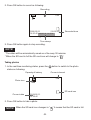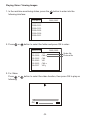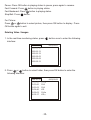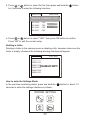
1
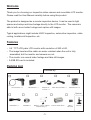
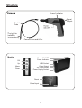
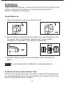
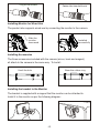
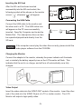
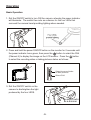
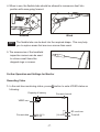
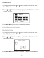
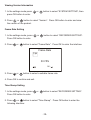
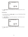
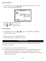
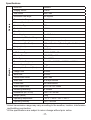
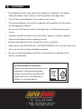
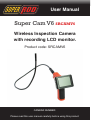
User Manual
Super Cam V6 SRCAMV6
Wireless Inspection Camera
with recording LCD monitor.
Product code: SRCAMV6
CAMERA NUMBER:
Please read this user manual carefully before using this product.
CONTENTS
Welcome .................................................................................................. 1
Features ................................................................................................... 1
Packing List .............................................................................................. 1
Structure ................................................................................................... 2
Installation ................................................................................................. 3
Operation .................................................................................................. 6
Basic Operation .................................................................................. 6
Other Operation and Settings for Monitor ........................................... 7
Recording Video .......................................................................... 7
Taking Photos .............................................................................. 8
Playing Video/Viewing Images .................................................... 9
Deleting Video/Images ................................................................ 10
Deleting a Folder .......................................................................... 11
Language Setting ........................................................................ 12
Video System Setting .................................................................. 12
Format ......................................................................................... 13
Default Setup ............................................................................... 13
Viewing Version Information ........................................................ 14
Frame Rate Setting ..................................................................... 14
Time Stamp Setting ..................................................................... 14
Recording Type ............................................................................ 15
Date/Time Setting ........................................................................ 16
Event Playback ............................................................................ 16
Specifications ............................................................................................ 17
Welcome
Thank you for choosing our inspection video camera and recordable LCD monitor.
Please read the User Manual carefully before using this product.
The product is designed as a remote inspection device. It can be used in tight
spaces and relays real-time footage directly to the LCD monitor. The camera is
able to both record video footage and capture still images.
Typical applications might include HVAC inspection, automotive inspection, cable
routing, boat/aircraft inspection, etc.
Features
• 3.5 ‘’ TFT-LCD palm LCD monitor with resolution of 960 x 240.
• The image head and the cable are water resistant when the unit is fully
assembled, but the monitor and camera are not.
• The monitor can record video footage and take still images.
• A 2GB SD card is included.
Packing List
Checked By:
Camera 9mm x 1
LCD Monitor x 1
Adapter for
monitor x 1
Video Output Cable x 1
AA Batteries x 4
Optional
USB Cable x 1
CD-ROM x 1
Magnet / Hook / Mirror
Rubber Ring x 1
-1-
Camera Collar 9mm
Micro
SD Card
Bracket
Structure
Structure
Camera
Power Indicator
Signal
Output
Flexible
Tube
Power
ON/OFF
Tthe hole for
Installing
installing
the accessory
Camera Lens and LEDs
Monitor
Monitor
OK
Up
OK
Menu
Up
Down
Menu
Down
Power ON/OFF
Power Indicator
Power
USBON/OFF
Socket
Power Indicator
Video Output
SD Card
USBSocket
Socket
Power
VideoSupply
Output
Socket
SD Card Socket
Power Supply Socket
Reset
Signal Input
Reset
Signal Input
-2-2-
Installation
Please install the batteries tube and insert the SD card first before using
product, and choose the accessory according to actual situation.
Steps of installation as following
Install Batteries
1. Using a screwdriver, remove screw and cover.
2. Remove battery compartment and insert four new AA batteries into
the proper slots in the battery compartment. Proper battery
orientation is indicated on the battery compartment.
AA
AA
AA
AA
3. Reinstall battery compartment and battery cover and screw as
before.
NOTE! Dry your hands before installation or replacing batteries.
Install the Camera with Flexible Tube
Connect the camera with tube to the body, make sure the keyed ends
are properly aligned. Once they are aligned, finger tighten the knurled
knob to hold the connection in place.
-3-3-
Plugged
the
socket
Plug to to
thethe
socket
Plugged
to
the
socket
Plugged
Plugged
to
the
socket
socket
Plugged to
to
the
socket
Fasten
Fasten the
the knurled
knurled knob
knob
Fasten
Fasten
the
knurled
knob
Fasten the
the knurled
knurled knob
knob
Installing
Monitor for
for Wired
Use
Install
Monitor
Wired
Use
Install
Monitor
for
Wired
Use
Install
Install
Monitor
for Wired
Wired Use
Use
Install Monitor
Monitor for
for
Wired
Use
The
product
also
supports
wired
useuse
by connecting
the
monitor
to the
camera.
The
product
also
supports
wired
by
connect
the
monitor
to
camera.
The product
product also
also supports
supports wired
wired use
use by
by connect
connect the
the monitor
monitor to
to camera.
camera.
The
The
product
also
supports
wired
The product also supports wired use
use by
by connect
connect the
the monitor
monitor to
to camera.
camera.
Slide
the
Slide
the
Slide
Slide
the
the
monitor
Slide
the
monitor
monitor
monitor
downward
monitor
downward
downward
downward
downward
Installed
Installed
Installed
Installed
successfully
Installed
successfully
successfully
successfully
successfully
Installing Accessories
To
Install
Accessory
To Install
Install Accessory
Accessory
To
To
Install
Accessory
To
Accessory
The
three
included
accessories,
hook
and
magnet)
all
attached
TheInstall
three
accessories
included with (mirror,
the camera
(mirror,
hook
and magnet)
The
three
included
accessories,
(mirror,
hook
and
magnet)
all
attached
The
The three
three included
included accessories,
accessories, (mirror,
(mirror, hook
hook and
and magnet)
magnet) all
all attached
attached
The
three
included
accessories,
(mirror,
hook
and
magnet)
all
attached
to
the
camera
by
the
same
way.
T
install
as
following:
all
attach
to
the
in
the same
To Install:
to the
the camera
camera camera
by the
the same
same
way.way.
Too
o install
install
as following:
following:
to
to
the
camera
by
by
the
same
way.
way.
T
T
o
install
as
as
following:
to the camera by the same way. To install as following:
Wear
the
rubber
ring
Wear
the
rubber
ring
Wear
Wear
the rubber
rubber ring
ring
Wear the
the
rubber
ring
Hook
the
hole
Hook
the
hole
Hook
Hook the
the hole
hole
Hook
the
hole
Install
the
of
Monitor
Installing
theBracket
bracket to
the
Monitor
Install
the
Bracket
of
Monitor
Install
Install
the
Bracket
of
Monitor
Install the
the Bracket
Bracket of
of Monitor
Monitor
The
bracket
with
a
magnet,
it
can
absorption
on
any
iron
objects.
The
bracketiswith
with
a magnet,
magnet,
it can
can that
absorption
on can
anybe
iron
objects.
The bracket
bracket
supplied
with a magnet
the monitor
attached
to.
The
The
bracket
with
aa
it
it
absorption
absorption
on
on
any
iron
objects.
objects.
The
bracket
with
a magnet,
magnet,
it can
can
absorption
on any
any iron
iron
objects.
Install
it
to
monitor
as
following
diagram:
Install
it
to
monitor
as
following
diagram:
Install
it
to
the
monitor
as
per
the
following
diagram:
Install
Install it
it to
to monitor
monitor as
as following
following diagram:
diagram:
Install
it
to
monitor
as
following
diagram:
-4-4-4-4-4-4-
Insert SD Card
Inserting
the Card
SD Card
Insert SD
After the SD card was inserted
After
the
SD
card
hasSD
been
inserted
After
the
SD
card
was
inserted
successfully into
card
socket,
SD card
successfully
into the SD
SD card
card socket,
the
successfully
the screen ofinto
monitor
willsocket,
appear
SD card
following
symbol
will be shown
on the monitor
the screen
of
monitor
will
appear
icon ; otherwise, it will
screen “ icon
”, otherwise
“ ” willitappear.
; otherwise,
will
appear
icon.
appear
icon.
Connecting the USB Cable
Connect USB Cable
Connect
theUSB
USB Cable
cable to the monitor and
Connect
Use
theend
USB
connect
the icon
the
other
to cable
a PC. to
The
USB online
Use
the USB
to USB
connect
the
monitor
to a cable
PC. The
online
will appear on the PC once successfully
3.5 Floppy Disk( A )
CD driver( G )
Mobile Disk( H )
monitor
to a PC.
ThePC.
USBOpen
online
icon appears
on the
My
inserted.
Openand
My
and locate
3.5 Floppy Disk( A )
CD driver( G )
Mobile Disk( H )
icon
appears
on Computer
the
My the
Computer,
findPC.
theOpen
Mobile
Mobile
The
video/picture
files
Computer,
and
find thefiles
Mobile
Disk.Disk.
the video/picture
in can
SD then
Disk.
the video/picture
files in
SDthe
be
copied/cut/played
back directly
from
card
could
be copied/cut/palyback
.
card
could
be computer
copied/cut/palyback
SD
card.
If the
can not play. the video files normally, please install
NOTE!
the
computer
not play
the CD-ROM.
video files normally, please install
the
video
playercan
software
in the
NOTE! If
the
video
playercannot
software
the
CD-ROM.
If the
computer
playinthe
video
files correctly, please install the
NOTE!
player
software from the CD-ROM.
Connect video
Monitor
Power
Connect Monitor Power
Connect the adapter to monitor, the power indicator will lights on red
Charging
the
Connect
theMonitor
adapter
to icon
monitor,
the of
power
indicator
will lights
on red
or the battery
capacity
on LCD
monitor
will twinkle
which
or
the battery
capacity
icon
onwill
LCD
of monitor
twinkle
indicates
charging,
and
turn
off power
afterwill
aindicator
full
charge:
Connect
thebeing
adapter
to the monitor,
whereby
the
willwhich
illuminate
indicates being charging, and will turn off after a full charge:
red, or similarly the battery capacity icon on the LCD monitor will flash. This
indicates that the unit is on charge, and will turn off automatically once fully
charged.
adapter
adapter
Video Output
Video Output
Insert the video cable into the VIDEO OUT socket of monitor. Insert the
Video
Insert
the video
socket
Insert
the
otherOutput
end
of the cable
cable into
into the
the VIDEO
VIDEO OUT
IN jack
of aof
TVmonitor.
or another
monitor.
other
end
of the
cable
intoVIDEO
the
VIDEO
IN jack
of a
TV or another
The LCD
Monitor
will
a high
quality
video.
Insert
the
video
cable
intooutput
the
OUT
socket
of the
monitor.
Insert themonitor.
other
TheofLCD
Monitor
outputIN
a jack
highofquality
end
the cable
into will
the VIDEO
a TV orvideo.
similar monitor. The LCD
Monitor will output a high quality video.
-5-5-5-
Operation
Operation
Operation
Basic
Operation
Basic Operation
Basic Operation
Basic
Operation
1. Roll the
ON/OFF switch to turn ON the camera, and the power indicator
1. Roll
the ON/OFF
turn
ONas
the
andthe
thetwin
power
indicator
will light
up, Theswitch
switchto
then
acts
a camera,
dimmer for
LEDs
that
will light
up,
switch
then
acts
as
a camera,
dimmer
for
LEDs
that
Roll
the ON/OFF
switch
toto
turn
ON
the
camera,
whereby
thetwin
power
indicator
1.1. Roll
the
ON/OFF
switch
turn
ON
the
andthe
the
power
indicator
surround
theThe
camera
on
the
imager
head
and
provide
lighting.
surround
theThe
camera
onthen
the imager
andfor
provide
lighting.
willilluminate.
light up,
actsas
asahead
adimmer
dimmer
for
LEDs
will
Theswitch
switch
then
acts
thethe
fourtwin
LEDs
thatthat
surround
thecamera
camera
on the
imager
headwhere
and provide
surround the
head
providing
lighting
needed.lighting.
ON
ON
F
OF
F
OF
F
OF
ON
Twin LEDs provide
lighting
Twin LEDs provide
lighting
Twin LEDs provide
lighting
2. Press and hold on the Power ON/OFF button of monitor for 2 seconds ,
Press
and hold
the
ON/OFF
button
on
theof
monitor
for 2
seconds
until
2.2. Press
and
hold
on power
thewill
Power
ON/OFF
button
monitor
for
2
seconds
and
power
indicator
be green,
then
press
button
to
select
the ,
and
power
indicator
will
be picture
green,
then
pressofon
button
to
select
the ,
the power
indicator
turns
green,
then press
the
button
the CH4
2. Press
and
hold
on
Power
ON/OFF
monitor
for
2
seconds
CH4(
channel
4)the
and
the
willbutton
display
LCDtoofselect
monitor
and
CH4(
channel
4)
and
picture
will
display
on pictures
LCD
monitor
and
and
power
will
be
green,
then
press
button
to
select
the
press
button
to select
recording
video
or take
status:
(Channel
4) indicator
to display
thethe
image
on the
LCD
monitor.
Pressofthe
button
press
button
to select
recording
video
orstatus
take
pictures
status:and
CH4(
channel
4)
and
the
picture
display
onas
LCD
of monitor
to select
the
recording
video
or
taking will
pictures
follows:
press
button to select recording video or take pictures status:
OK
Select to record video
or
taketo
pictures
Select
record video
or takeCH4
pictures
Select
Select to record video
Select
or takeCH4
pictures
OK
OK
Select CH4
Rollthe
the ON/OFF
ON/OFF switch
switch on
3.3.Roll
of the
3. camera
Roll
the for
ON/OFF
of light
betterswitch
image
camera
to dim/brighten
the
image
3. camera
Roll
the for
ON/OFF
switch
of
effect.
produced
bybetter
the four
LEDS.
effect. for better image
camera
effect.
ON
ON
ON
-6-6-6-6-
F
OF
F
OF
F
OF
The switch acts
as switch
a dimmer
The
acts
as switch
a dimmer
The
acts
as a dimmer
4.4.When
in use,
thethe
flexible
should
be allowed
to manoeuvre
into
When
in use,
tubetube
should
easily
maneuver
itself intoitself
position
going forward.
position
with ease going forward.
4. When in use, the tube should easily maneuver itself into position
going forward.
4. When in use, the tube should easily maneuver itself into position
going forward.
wired
Wired
wireless
Wireless
wired
wireless
tube can be bent into a certain shape.
This may help
wired
wireless
TIP! The flexible
flexible
canbe
bebent
bent
into
a required
certain shape.
help
Theexplore
flexible tube
tube
can
into
the
shape. This
This may
may help
TIP! The
you
the tube
into
narrow
areas.
TIP!
Theexplore
flexible the
tube
can
be
bent
into
a
certain
shape.
TIP! you
tubethat
intoare
narrow
areas. than usual. This may help
you to explore areas
more narrow
you explore the tube into narrow areas.
5. The accessories of Handhold
5. The accessories of Handhold
Inspection
Camera
can be
The
accessories
of Handhold
Inspection
Camera
can
be
5.5.
The
accessories
of the
handheld
used
to
retrieve
small
items
Inspection
Camera
can
be
used
to
retrieve
small
items
inspection
camera
can
be
used
used
to
retrieve
small
items
like dropped
dropped rings
rings or
or screws.
screws.
like
dropped
screws.
tolike
retrieve
smallrings
itemsor
like
dropped rings or screws.
Further Operation and Settings for Monitor
Other
OtherOperation
Operationand
andSettings
Settingsfor
forMonitor
Monitor
Other
Operation
and
Settings
for
Monitor
Other Operation and Settings for Monitor
Recording Video
Record
Record Video
Video
Video monitoring status, press
1.Record
In the real-time
button to enter VIDEO status as
1. In
In the
the realtime
realtime monitoring
monitoring status,
status, press
press
button to
to enter
enter VIDEO
VIDEO
1.
button
following:
status
as following:
following:
status
as
1. In
the realtime
monitoring status, press
button to enter VIDEO
Capacity
of
battery
Current
channel
Capacity
OfBattery
Battery
Current
Channel
status as following:
Capacity
Of
Current
Channel
Capacity Of Battery
Current
CH4 Channel
CH4
VIDEO
VIDEO
iconicon
VIDEO
icon
CH4
VIDEO
icon
SD Card Icon
Current
Current
Current
Datedate
Date
Current
Date
2009/02/11
[00:45:43]
2009/02/11
14:50:40
14:50:40
2009/02/11
14:50:40
[00:45:43]
-7-
-7-
-7-7-
[00:45:43]
Card
Icon
SDSD
card
icon
Left Time
Left
Time
Time
left
SD Card Icon
Left Time
2. Press OK button to record as following:
2. Press OK button to record as following:
2. Press OK button to record as Recording
following:
Recording
Recording
CH4
CH4
2009/02/11
[00:05:43]
2009/02/11
[00:05:43]
14:50:40
2009/02/11 14:50:40
14:50:40 2009/02/11 14:50:40
Recorded Time
Recordedtime
Time
Recorded
Time Stamp
Time Stamp
stamp
3. Press OK button again to stopTime
recording.
3. Press OK button again to stop recording.
3. Press OK button again to stop recording.
Notice!
Notice!
NOTE!
The will
Video
will be automatically
as 30
a file
every 30 minutes.
* The*
be automatically
saved as asaved
file every
minutes.
*video
The Video
will be automatically
saved
as a file
every 30 minutes.
* SD
is full
when
thecard
SD icon
cardwill
icon
change
.
* When
thecard
SD card
is full
the SD
change
to “ to
”.
F
* SD card is full when the SD card icon change to
.
Taking photos
Take photo
Take photo
1. In the real-time monitoring status, press the
button to switch to the photo
1.
In the
realtime monitoring status, press
button to switch to photo
status
as following:
1.
In the
realtime monitoring status, press
button to switch to photo
taking status as following:
taking status as
following:
Capacity of battery
Current channel
Capacity Of Battery
Capacity Of Battery
Current Channel
Current Channel
CH4
CH4
Photo
Photo
icon
Photo
Icon
Icon
SD
icon
SDcard
Card
Icon
Current
Current
date
Current
Date
Date
SD Card Icon
2009/02/11
2009/02/11
14:50:40
14:50:40
2. Press OK button to take a photo.
2. Press OK button to take photo.
2. Press OK button to take photo.
NOTE! When the SD card icon changes to “ F ” it means that the SD card is full.
when the SD card icon change to
which means SD
Notice! when the SD card icon change to
which means SD
Notice! card is full.
-8card is full.
-8-8-
Playing Video / Viewing Images
Play Video/Picture
Play Video/Picture
In
realtime
monitoring
status,
press button
button
to enter
into the
1.1.
thethe
real-time
monitoring
status,
press the
to enter
into the
1.InIn
the
realtime
monitoring
status,
press
button
to enter
into the
following
interface:
following
interface:
following
interface:
PLAYBACK
PLAYBACK
2009-01-10
2009-01-10
2009-01-11
2009-01-11
2009-01-12
2009-01-12
2009-02-05
2009-02-05
2009-02-09
2009-02-09
2009-02-11
2009-02-11
2. Press
or
2.2.Press
Press
into it: oror
into it:
0001/0007
0001/0007
button to select folder, then press OK button to enter
button
to to
select
the folder
press
OK to
button
select
folder,and
then
press
OKenter:
button to enter
2009-01-10
2009-01-10
05:53:00
05:53:00
05:53:00
05:53:00
05:53:03
05:53:03
05:56:40
05:56:40
05:59:03
05:59:03
06:05:17
06:05:17
CH4
CH4
CH4
CH4
CH4
CH4
VID
VID
CH4
CH4
VID
VID
0002/0005
0002/0005
mean
Video
filevideo file
video file
mean file
picture
file
Picture
mean picture file
3. For Video:
3. For Video:
oror button
to select
the video
then press
OK to play
as as
For
3.Press
PressVideo:
button
to select
video,function,
then press
OK button
to play
Press
or
button to select video, then press OK button to play as
following:
following
interface:
following interface:
OK
OK
2009/01/10
2009/01/10
2009/01/10
-9-9-9-
05:53:00
05:53:00
05:53:00
:
:
Pause:Pause:
Press OK
button
playing in
status
to pause,
press
again to resume.
press
OKinbutton
playing
status
to pause;
press again
toinresume;
Fast Forward: Press
button
playing status.
Fast Forward:
button
playing status;
Fast Backward:
Press press
button in
playinginstatus.
Fast Backward: press
button in playing status;
Stop/Exit: Press
button.
Stop/Exit: press
button.
For Picture:
For Picture:
Press
or
button to select picture, then press OK button to display. Press
Press
or
button to select picture, then press OK button to
OK button
again press
to exit.OK button again to exit.
display,
Deleting Video / Images
Delete Video/Picture
1. In1.
theInreal-time
monitoring
status, press
button once
to enter
theto
following
the realtime
monitoring
status, press
button
once
enter into
interface:
the following interface :
PLAYBACK
0001/0007
2009-01-10
2009-01-11
2009-01-12
2009-02-05
2009-02-09
2009-02-11
2. Pressor orbutton
button
to select
folder,
then
button
2. Press
to select
folder, then
press
OKpress
buttonOK
to enter
theto enter
into interface:
the following interface:
following
2009-01-10
05:53:00
05:53:00
05:53:03
05:56:40
05:59:03
06:05:17
0002/0005
CH4
CH4
CH4
VID
CH4
VID
-10-10-
3.Press
Press oror button
button
select
press
andand
hold
onthe button
for 2
3.
to to
select
the file,
file,
then
press
hold
button
3. 3.
Press
Press or or button
button
to
to
select
select
file,
file,
press
press
and
and
hold
hold
onon button
button
forfor
2 2
seconds
willtoenter
the
following
interface:
for
2seconds
seconds
enter
thethe
following
interface:
seconds
willwill
enter
enter
the
following
following
interface:
interface:
2009-01-10
0002/0005
2009-01-10
2009-01-10
0002/0005
0002/0005
05:53:00 CH5
DELETE
FILE?
05:53:00
05:53:00CURRENT
CH5
CH5
05:53:00
CH5
DELETE
DELETE
CURRENT
CURRENT
FILE?
FILE?
05:53:00
05:53:00 CH5
CH5
05:53:03 CH5
NO
05:53:03
05:53:03 CH5
CH5
NO NO
05:56:40 CH5
YES
05:56:40
05:56:40 CH5
CH5
05:59:03 CH5
YESYES
05:59:03
05:59:03 CH5
CH5
06:05:17 CH5
06:05:17
06:05:17 CH5
CH5
4. Press
or
button to select YES , then press OK button will be
4.
to to
select
“YES”,
then
OK
button
tobutton
confirm.
4.Press
4.
Press
Press oror or button
button
button
to
select
select
YES
YES,press
then
, then
press
press
OKOK
button
willwill
bebe
deleted has been selected by the file; NO will be exit.
deleted
deleted
been
been
selected
byby
thethe
file;
file;NONO willwill
bebe
exit.
exit.
Press
“NO”has
tohas
exit
theselected
current
setup.
Delete Folder
Deleting
a
folder
Delete
Delete
Folder
Folder
Delete
folder
same
as
delete
,but make
sure the
folder
is the
empty,
Deleting
a folder
is is
theis
same
process
asfile
deleting
a file,
however
make
sure
Delete
Delete
folder
folder
is
same
same
as
as
delete
delete
file
file
,but
,but
make
make
sure
sure
the
the
folder
folder
is is
empty,
empty,
otherwise not delete it and appear a warning interface:
folder
is
empty, not
otherwise
the
warning
will
appear:
otherwise
otherwise
not
delete
delete
it following
and
it and
appear
appear
a warning
ainterface
warning
interface:
interface:
PLAYBACK
0001/0007
PLAYBACK
PLAYBACK
0001/0007
0001/0007
2009-01-10
2009-01-10
2009-01-10
2009-01-11
2009-01-11
2009-01-11
2009-01-12
2009-01-12
2009-01-12
FOLDER NOT EMPTY
2009-02-05
FOLDER
FOLDER
NOT
NOT
EMPTY
EMPTY
2009-02-05
2009-02-05
2009-02-09
2009-02-09
2009-02-09
2009-02-11
2009-02-11
2009-02-11
to enter
the Setting
Mode
HowHow
to
enter
the
Settings
Mode
How
How
toto
enter
enter
the
the
Setting
Setting
Mode
Mode
In the
real-time
monitoring
status,
press
andpress
hold the
button
about 1-2
In the realtime monitoring status,
and hold
on for button
for
In In
thethe
realtime
realtime
monitoring
monitoring
status,
status,
press
press
and
and
hold
hold
onon button
button
forfor
about
to enter
into
setting interface as follows:
seconds
to 1~2
enterseconds
the settings
interface
as the
follows:
about
about
1~2
1~2
seconds
seconds
to to
enter
enter
into
into
thethe
setting
setting
interface
interface
asas
follows:
follows:
SYSTEM SETTING
SYSTEM
SYSTEMSETTING
SETTING
-11-11-11-11-
Language Setting
1. Language
In the settings
mode, press
or
button to select “SYSTEM SETTING”.
Setting
Press OK to enter.
1. In the setting
mode press
or
button to select SYSTEM
Language
Setting
SETTING
press OK button to enter
2. 2.
Press
to select
“Language”,
press the
OK button
to enter
the to
1.
In the or
setting
mode
press
orLanguage
button
to press
select
SYSTEM
Press
or button
button
to
select
the
OK
button
following
interface:
SETTING
OK button
to enter
enter
into thepress
following
interface
2. Press
or
button to select Language
press the OK button to
enter into the following interface
OK:
English
English
Press or or button
button
to select
a suitablelanguage.
language
3. 3.
Press
to OK:
select
the appropriate
4. Press OK button to confirm and exit.
3. Press
or
button to select a suitable language
4. Press OK button to confirm and exit.
4. Press OK button to confirm and exit.
Video
System
Setting
Video
System
Setting
1.
In the
settingSetting
mode press
or
button to select SYSTEM
Video
System
1. In the
settings mode,
press
or to
button
SETTING
press
OK button
enterto select “SYSTEM SETTING”.
Press
OK button
enter. to
1.
In the
setting
press
button
to select
SYSTEM
2.
Press
or tomode
button
select orVideo
System
press
OK button to
SETTING
OK button
to enter
enter
into thepress
following
interface:
Press or or button
button
to select
System
button to
2. 2.
Press
to select
“VideoVideo
System”.
Press OKpress
buttonOK
to enter
enter into the following interface:
Video system
the following interface:
NTSC
Video system
NTSC
3. Press
or
NTSC
PAL
OK
NTSC
NTSC
PAL
OK
NTSC
button to select right type press OK button to
confirm
exit. to select the right type. Press OK to confirm and exit.
3. Press
or andbutton
3. Press
or
button to select right type press OK button to
confirm and exit.
-12-
Format
Format
1. In the settings mode, press
or
button to select “SYSTEM SETTING”.
Format
Press
to enter.
1. In
theOK
setting
mode press
or
button to select SYSTEM
SETTING
button to
1. In
the settingpress
modeOKpress
orenter
button to select SYSTEM
2.
or
button
tobutton
select“Format”.
OK button
enter
SETTING
OKto
to Format
enter Presspress
2. Press
Press
or press
button
select
OK button
to entertothe
into
the
following
interface
2. Press
or
button to select Format
press OK button to enter
following interface.
into the following interface
FORMAT WILL
ERASE ALL DATA
FORMAT
WILL
ARE
YOU SURE?
ERASE ALL DATA
ARE YOU SURE?
NO
YES
NO
YES
3. Press
Press
or button
button to
to select
press
OK toOK
erase
all data.
3.
or
select“YES”,
YES then
, then
press
button
will
Press “NO”
to exit
the
erase
all or
data;
NOsetup.
be exit.
3. Press
button
towill
select
YES , then press OK button will
erase all data; NO will be exit.
Default Setup
Default Setup
Default
Setup mode, press
1. In
In the
to select
“SYSTEM
SETTING”.
1.
thesettings
setting mode press or or button
button
to select
SYSTEM
Press
button
to enter.
SETTING
press
OKpress
button to
1. In
theOK
setting
mode
orenter
button to select SYSTEM
2. Press
button
selectto enter
Default Setup
press OK button to
SETTINGor press
OKtobutton
enter
following
interface:
2.
or
select
Default
Setup
press
OKtobutton
2. Press
Press into
orthe button
button totoselect
“Default
Setup”.
Press OK
button
enter to
enter
into the
following interface:
the following
interface:
RESTORE DEFAULT
ARE YOU SURE?
RESTORE DEFAULT
ARE YOU SURE?
NO
YES
NO
YES
3.
or
button
select
YESthen
, then
button
will
3. Press
Press
or
button totoselect
“YES”,
presspress
OK to OK
restore
default.
restore
default;
be exit.
3. Press
orto exit
button
to will
select
YES , then press OK button will
Press “NO”
theNO
setup.
restore default; NO will be exit.
-13-
Viewing Version Information
View Version Information
1. In the settings mode press
or
button to select “SYSTEM SETTING”, then
press
OK button
enter. ,press
1.
In the
settingtomode
or
button to select SYSTEM
SETTING , then press OK button to enter;
Press oror button
button
select
Version
press
OKtobutton
to enter
2.2.
Press
to to
select
“Version”.
Press, OK
button
enter and
view
and view the version of product.
the version of the product.
Frame Rate Setting
Frame Rate Setting
1. In the settings mode, press
or
button to select “RECORDER SETTING”.
1. In the setting mode press
or
button to select RECORDER
Press OK button to enter.
SETTING
press OK button to enter
2. Press
or
button to select Frame Rate
press OK button to
2. Press
or interface:
button to select “Frame Rate”. Press OK to enter the interface:
enter into
Frame Rate
Fps
30 FPS
OK:
3. Press
or
button to select a suitable frame rate.
3. Press
or
button to select suitable frame rate;
4. Press OK button to confirm and exit.
4. Press OK to confirm and exit.
Time Stamp Setting
Time Stamp Setting
1.1.
In In
thethe
settings
mode,
press press
or
to select
SETTING”.
setting
mode
orbutton
button
to “RECORDER
select RECORDER
SETTING
OK button to enter
Press
OK button press
to enter.
2. Press
or
button to select Time Stamp
press OK button to
enter into the following interface:
2. Press
or
button to select “Time Stamp”. Press OK button to enter the
following interface:
-14-
Time Stamp
OK:
off
off
3. Press
or
button to
“Off” and
press
OKbutton
to confirm
or
button
toselect
selecteither
Off“On” orOn
press
OK
to
3. Press
and
exit. and exit.
confirm
Recording Type
Recording Type
1. In the settings mode, press
or
button to select “RECORDER SETTING”.
or
button to select RECORDER
Press
buttonmode
to enter.press
1. In
theOK
setting
SETTING
press OK button to enter
2.
or
button
select
Recording
Type
press
OK to
button
2. Press
Press
or
button totoselect
“Recording
Type”.
Press OK
button
enter
to enter into the following interface:
the following interface:
Recording Type
OK:
VIDEO
VIDEO
3. Press
or
button to select “STILL” “VIDEO”. Press OK to confirm and
3. Press
or
button to select STILL
VIDEO
press OK button
exit.
to confirm and exit.
-15-15-
Date/Time Setting
Date/Time Setting
In the
setting
mode
or
to“Date/Time”.
select Date/Time
1. 1.
In the
settings
mode,
press press
or
buttonbutton
to select
Press OK
press
OK button
to enter
into the following interface:
button
to enter
the following
interface:
Date/Time
2009 / 02 / 13
09 : 51
OK:
2. Press OK to select the Date or Time
2. Press OK button to select Date or Time;
Press
or
button to modify
press
or
button to modify;
Press
button
to confirm
and exit
press
button
to confirm
and exit.
Event Playback
EVENT PLAYBACK
1. In the settings mode, press
or
button to select “EVENT PLAYBACK”.
Press
OKthe
button
to enter.
1. In
setting
mode press
or
button to select EVENT
PLAYBACK
press OK button to enter;
Other
operation
Play Video/Picture
2. For2.other
operation,
see see
“Play Video/Picture”
Delete Video/Picture
Delete Folder section.
“Delete Video/Picture”, “Delete Folder” section.
FCC INFORMATION
This device complies with part 15 of the FCC rules. Operation is subject to the
following two conditions:
(1) This device may not cause harmful interference
(2) This device must accept any interference received, including interference that
may cause undesired operation. Changes or modifications not expressly
approved by the party responsible for compliance could void the user’s authority
to operate the equipment.
-16-16-
Monitor
Camera
Specifications
Model No.
GB8803
Imaging Sensor
CMOS
Total Pixels
640 x 480
Horizontal View Angle
45 degrees
Transmission Frequency
2468 MHz
Minimum Illumination
0 lux
Modulation Type
FM
Bandwidth
18 MHz
Tube Diameter
9mm
Power Supply
4 x AA Batteries
Unobstructed Effective Range
10m
Waterproof Capacity
IP67 (only for imager head)
Dimensions (W x D x H)
186 x 145 x 41mm (Excluding Flexible Tube)
Weight (about)
450g
Model No.
GB7307
LCD Screen Type
LCD 3.5” TFT-LCD
Effective Pixels
320 (RGB) x 240
Video System
PAL / NTSC
Transmission Frequency
2414MHz, 2432MHz, 2450MHz, 2468MHz
Exterior Supply Voltage
5VDC
Consumption Current (Max.)
500 mA
Charge Time
3 hours
Work Time
2 hours
Picture/Video Pixels
640 x 480
Video Size
27M byte /minute
Frame Rate
30 frame/second
Video Output Level
0.9 1.3VP-P @ 75ohm
Receiving Sensitivity
≤ -85dBm
Dimensions (W x D x H)
100 x 70 x 25 mm
Weight (about)
140g
Operating Temperature
-10 °c ~ +50°c / 14°F ~ 122° F
15% ~ 85%RH
Operating Humidity
* Actual transmission range may vary according to the weather, location, interference
and building construction.
* All the specifications are subject to minor change without prior notice.
-17-
!
•
•
•
•
•
•
•
•
•
•
CAUTIONS
FCC INFORMATION
The apparatus shall not be exposed to dripping or splashing. No objects
This device complies with part 15 of the FCC Rules. Operation is subject
filled with liquids,
such
as vases,
shall be placed on the apparatus.
to the
following
two conditions:
(1) this device may not cause harmful interference,
Turn off the Camera/Monitor
if accept
the system
is not in
use. including
(2) this device must
any interference
received,
interference that may cause undesired operation. Changes or
The Camera/Monitor
can not
only
be completely
from
modifications
expressly
approved bydisconnected
the party responsible
forthe mains
compliance could void the user s authority to operate the equipment.
by unplugging the
adapter.
Do not cut the DC power cable of the apparatus to fit with another power
! CAUTIONS
source.
The apparatus shall not be exposed to dripping or splashing and that
Attention should be
drawn to the environment aspects of battery disposal.
no objects filled with liquids, such as vases, shall be placed on the
apparatus.
Remove the batteries
when
cleaning the
unit.
Turn off
the Camera/Monitor
if the
system is not in use.
The Camera/Monitor can only be completely disconnected from the
Remove the batteries
storing
the unit for a long time.
mainsbefore
by unplug
the adapter.
Do not cut the DC power cable of the apparatus to fit with another
When necessary, power
REPLACE
source. ALL FOUR BATTERIES in this unit with new ones.
Attention should be drawn to the environment aspects of battery
Use only the size disposal.
and type of battery specified.
Remove the batteries when cleaning the unit.
Remove
the batteries
before
storing the
unit for as
a long
time.
Be sure to install the
battery
with the
correct
polarity
indicated
in the
When necessary, REPLACE ALL FOUR BATTERIES in this unit with new
battery compartment.
ones.
Use only the size and type of battery specified.
Be sure to install the battery with the correct polarity as indicated in
the battery compartment.
EU Environmental Protection
Waste electrical
products should
not be
EU Environmental
Protection
disposed ofWaste
withelectrical
household
waste.
products
should not be
disposed of with household waste.
Please recycle
facilities
exist.
Pleasewhere
recycle where
facilities
exist.
yourAuthority
Local Authority
Check withCheck
yourwith
Local
or or
retailer for recycling advice.
retailer for recycling advice.
• Tel: +44 (0) 1495 792000
• Email: [email protected]
• Web: www.super-rod.co.uk
22