1
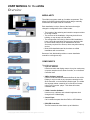
USER MANUAL
for the eVidia
This document will help you use, maintain and resolve issues
with the eVidia outdoor display
Introduction
Unquestionably the most advanced large-format digital display ever!
Our new HDVGT technology implements highly intelligent algorithms
and circuitry at the pixel level that enables full control of the elements
within the pixel itself. This groundbreaking technology dramatically
increases the sharpness, color reproduction and uniformity. Dense
display modularity allows for greater flexibility to create custom
shapes and contours.
eVidia User Manual 2.15.04rw
Multimedia
3300 Monier Circle
Rancho Cordova, CA 95742
Tel: (916) 852-4220
Fax: (916) 852-8325
Email: [email protected]
http://www.MultiMediaLED.com
USER MANUAL for the eVidia
Table of Contents
Contents
Table of Contents
Overview
Modularity . . . . . . . . . . . . . . . . . . . . . . . . . . . . . . . . . . . . . . . 3
Components . . . . . . . . . . . . . . . . . . . . . . . . . . . . . . . . . . . . . 3
User activities . . . . . . . . . . . . . . . . . . . . . . . . . . . . . . . . . . . . 4
Power
Overview . . . . . . . . . . . . . . . . . . . . . . . . . . . . . . . . . . . . . . . . 5
Powering Down . . . . . . . . . . . . . . . . . . . . . . . . . . . . . . . . . . 5
Powering Up . . . . . . . . . . . . . . . . . . . . . . . . . . . . . . . . . . . . . 5
eVidia Controller Software
Scheduling on, off and display brightness . . . . . . . . . . . . . . 7
Re-calibrating color . . . . . . . . . . . . . . . . . . . . . . . . . . . . . . . 8
Identifying system errors . . . . . . . . . . . . . . . . . . . . . . . . . . 10
Identifying software/firmware version . . . . . . . . . . . . . . . . . 10
Preventive Maintenance
Error log review . . . . . . . . . . . . . . . . . . . . . . . . . . . . . . . . .
PC Maintenance Routines . . . . . . . . . . . . . . . . . . . . . . . . .
Cleaning the display . . . . . . . . . . . . . . . . . . . . . . . . . . . . . .
Inspection for moisture . . . . . . . . . . . . . . . . . . . . . . . . . . . .
inspection of data connections . . . . . . . . . . . . . . . . . . . . . .
inspection of electrical connections . . . . . . . . . . . . . . . . . .
12
12
13
14
17
17
Troubleshooting
How to proceed: . . . . . . . . . . . . . . . . . . . . . . . . . . . . . . . . . 18
Beginning the troubleshooting process: . . . . . . . . . . . . . . . 18
Glossary
Page 2
© Copyright 2003, Multimedia LED. All rights reserved
USER MANUAL for the eVidia
Overview
MODULARITY
The eVidia is a system made up of modular components. This
allows for flexibility in design while keeping design, assembly,
maintenance and repair costs to a minimum.
Each installation is unique. Some of the factors that might
change the configuration of the eVidia include:
• The location of the authoring and controller computer relative
to the sign location.
• The structure of the installation: A sign may be built into a
building, or may sit atop a 50 foot tower.
• The arrangement of the face(s): Some eVidia installations
have a single face and allow easy access to the back side
for service while others may be installed back-to-back.
Some may require a lift to access, others may allow walk-up
service.
• Most eVidia installations are flat, but there are eVidia
installations with curved faces.
Because of this, Multimedia provides a custom installation
manual for each sign we ship.
COMPONENTS
The eVidia components:
• Flyer Pro Software
Used to schedule and display content. It may be used on any
computer networked to the Show Controller, or on the Show
Controller itself.
• 2MPro Software (optional)
Used to create text-based content and effects for the eVidia
Display. It may be used on any computer networked to the
Show Controller, or on the Show Controller itself. The eVidia
also accepts content created in AVI or QuickTime formats
using Flyer Pro as the “player.” This allows full motion,
cinematic video.
• eVidia Controller Software
Used to set up, calibrate, and schedule brightness level
changes in the eVidia display.
• Control Pipes
Cat 5e cables that pass data from DX2s to LED Modules
• DX2 LED Controllers
The DX2 controls the video feed to up to 8 Modules.
© Copyright 2003, Multimedia LED. All rights reserved
Page 3
USER MANUAL for the eVidia
Overview
COMPONENTS (CONTINUED)
• Module Power Supplies
Each Power Supply feeds up to 16 Modules
• Fast Pipe
A Cat 5e cable from the SIM to the DX2
• SIM (Sign Interface Module)
The SIM breaks down the video into modulesized chunks, and sends the data to the DX2s
over the Fast Pipe. It receives its instructions from
the eVidia Controller Software and the Flyer Pro
Software over RS-232 or fibre.
• Sparrow (optional)
A fibre optic converter, which is required when the
authoring system is separated from the sign by
over 50 ft.
• Show Controller:
A PC with a special video card and software
used to originate the video that is displayed on
the eVidia. The Show Controller may also be
equipped with optional video processing hardware
and software for live video — Multimedia
videoPro. This feature is not covered in this
manual.
USER ACTIVITIES
User activities that are covered in this manual include:
•
•
•
•
•
•
•
Powering-up and powering-down
Scheduling on, off and display brightness
Re-calibrating color
Identifying system errors
Identifying temperature-related issues
Cleaning the display and enclosure
Troubleshooting the display
Casual users should avoid, or seek assistance with:
• Altering “Fast Pipe” configuration
• Changing color calibration settings
• Working with high-voltage electrical components
If you are unsure of how to proceed, check with
Multimedia technical support.
• LED Display Modules
The LED Display Modules are self-contained
printed circuit boards (PCBs) tying the lightemitting diodes (LEDs) together to the electronics,
encased in black plastic to provide maximum
contrast and durability. They come in several pixel
densities. In the eVidia Controller software they
are also referred to as “Display Blocks.”
• eVidia Enclosure
Custom built to the requirements of the installation
location, each enclosure is built to be sturdy, water
resistant, and to run unattended in harsh, outdoor
conditions. Periodic cleaning is all that is normally
required. Enclosures may use forced air cooling or
air conditioning.
Multimedia is proud of each unit we ship, and we will
work with you to keep it, and you, happy. If at any
time this user manual doesn’t answer your questions,
contact our support department, and we’ll be happy to
help!
Page 4
Contact Info:
Multimedia
3300 Monier Circle
Rancho Cordova, CA 95742
Tel: (916) 852-4220
Fax: (916) 852-8325
Email: [email protected]
http://www.MultiMediaLED.com
© Copyright 2003, Multimedia LED. All rights reserved
USER MANUAL for the eVidia
Power
OVERVIEW
POWERING DOWN
The eVidia display will run continuously in
ordinary conditions. If there is no content, the
display can be turned off through the eVidia
Controller software, while leaving the remaining
components powered up.
1) The Show Controller is a PC running the Windows
2000 or Windows XP operating system. If the entire sign
needs to be powered down, we recommend using the
Windows shutdown procedure first. Then the entire sign
can be powered down using the Master Switch.
Reasons to Power Up or Down:
•
•
•
•
a. Select “Start Menu” in lower left side of screen.
b. Scroll down the menu to “Shut Down” and
click mouse.
Sign needs to be serviced
Troubleshooting display problems
Power outages
Heavy electrical storms
2) Turn off sign at Master Switch
The electrical components of the eVidia have
separate breaker switchs in the central breaker
box. There is usually a Master Switch which
overrides the separate breakers. In addition several of the components have individual switches,
most notably the Show Controller, the Sparrow,
and the SIM.
POWERING UP
Ordinarily, the sign can be powered up using the Master
Switch. All components, including the Show Controller
should “boot up” successfully. However, under some
circumstances, it may make sense to boot the system
sequentially.
If this procedure fails repeatedly at any step, refer to the
“Troubleshooting” portion of this manual.
Status LED
Showing “dot”
Status LED
Showing “d”
Be sure to shut down the
Windows operating system
before powering down
Status LED
Rotating
Pattern
© Copyright 2003, Multimedia LED. All rights reserved
1. Be sure the Master Switch is in the “off” position
2. Turn all breakers to the “off” position
3. Turn the Master Switch to the “on” position
• At this point, the entire sign, and all its
components should remain powered down. If not,
recheck to insure all breakers in the breaker box
are in the “off” or “tripped” position.
4. Turn breaker for the display to the “on” position
• Wait 15 seconds
• The DX2 status LED should show a “dot”.
• The display and the SIM should now be powered
up. (If the SIM is not located in the enclosure,
power it up separately.)
5. Turn the breaker for the Sparrow to the “on” position
• Display should light up, and the Multimedia Logo
should scroll diagonally up the screen.
• The DX2’s LED display should show “d”. This
means the DX2’s are waiting for data.
6. Turn on power to the Show Controller.
• The Show Controller may take a few minutes to
fully boot. When it is ready the DX2s should show
a rotating pattern. This means the sign is ready
and fully functional.
Page 5
USER MANUAL for the eVidia
eVidia Controller Software
The eVidia Controller Software is used to set up, calibrate,
and schedule brightness level changes in the eVidia display.
Many of its features need never be accessed after the eVidia
leaves the Multimedia factory. However, there are several
activities that an eVidia user may undertake, and others that
may be requested by Multimedia support staff in the process
of troubleshooting.
User activities that are covered in this section of the
manual include:
•
•
•
•
•
Scheduling on, off and display brightness
Re-calibrating color
Identifying system errors
Identifying temperature-related issues
Identifying software/firmware version
Some of the more critical technical settings are passwordprotected, and won’t be described in this manual.
Casual users should avoid, or seek assistance with:
Main window of the eVidia Controller software.
• Altering “Fast Pipe” configuration
• Changing color calibration settings
• Altering settings in the “Faces” window
If you are unsure of how to proceed, check with Multimedia
technical support.
Page 6
© Copyright 2003, Multimedia LED. All rights reserved
USER MANUAL for the eVidia
eVidia Controller Software
SCHEDULING ON, OFF AND DISPLAY
BRIGHTNESS
The eVidia can be scheduled to adjust the brightness of
the display according to the time of day. During daylight
the display brightness should be higher than at night.
Intermediate settings for dusk and dawn can be set as well.
To adjust the schedule:
• Click the “Scheduling” button to open the “Brightness
Scheduling” window.
“Scheduling” button
“Scheduling” window
This window contains four columns:
• Enable: When selected, the other fields in that row are
active.
• Sign Off: When selected, the sign display is blank.
• Brightness (%): Sets the relative brightness of the
entire display. This field may contain a value between
“0” (off) and “100” for full brightness. We recommend a
brightness no greater than 80% in full daylight.
• Start Time: Input the time you want the change to take
place. This is a 24-hour clock. “00:01” is one minute past
midnight. “24:00” is midnight.
The Brightness Scheduling window contains four rows
allowing you to adjust the brightness or turn the display on or
off up to 4 times in a 24 hour period.
To activate changes to the schedule:
• Click the “OK” button (the Brightness Scheduling window
will close).
• In the main window, click the “Update Entire Sign”
button.
“Update Entire Sign” button
To turn off the sign at a particular time:
• Uncheck “Enable” check box in all rows except the first
• Check the “Sign Off” check box in the first row
• Set the time for the time you want the display to turn off.
• Click the “OK” button (the Brightness Scheduling window
will close).
• In the main window, click the “Update Entire
Sign” button.
To turn the display on immediately:
• Click the “Sign On” button
To turn the display off immediately:
• Click the “Sign Off’ button
“Sign On” & “Sign Off” buttons
To disable schedule:
• Click “Disable Schedule” button
© Copyright 2003, Multimedia LED. All rights reserved
Page 7
USER MANUAL for the eVidia
eVidia Controller Software
RE-CALIBRATING COLOR
Multimedia calibrates each display before it leaves the
factory. Adjustments may be useful to create effects,
compensate for aging components, or to compensate for
environmental lighting.
Warning: Altering these settings from factory defaults may
create calibration problems that can only be corrected
by specially equipped and trained engineers. Proceed
with caution. If you are unsure of these settings DO NOT
ALTER them without direction from Multimedia support.
Adjusting the Palette:
To adjust the palette, click the “Palette” button. The Palette
Adjustment window will open.
The following adjustments are available:
• Brightness (%)
We recommend a daylight brightness of 80%, which
is sufficient for bright daylight conditions. Dusk and
nighttime settings can be adjusted to your preferences.
Keep in mind that the brightness in the scheduling
screen reflects the settings here. Changing either will
update the other.
“Palette” button
• Gamma (recommend values from 1.75 to 2.5)
Default is 2.25. Effectively adjusts color contrast. A
higher value will darken shadows and midtones in
images reducing contrast. A higher value will darken
shadows and midtones increasing contrast. Gamma
adjusts for non-linear hardware brightness to create
visually linear output.
• Lower Clipping (0-255)
Default is 0 (no change). Altering this setting allows the
darkest shades in an image to be adjusted to black.
This can enhance video or photographic images under
some circumstances, but adjusting Gamma is the
preferred method.
• Upper Clipping (0-255)
Default is 255 (no change). Altering this setting allows
the lightest shades of an image to be adjusted to white.
This can eliminate detail in bright parts of an image.
(continued)
“Palette Adjustment” window
Page 8
© Copyright 2003, Multimedia LED. All rights reserved
USER MANUAL for the eVidia
eVidia Controller Software
White (255)
No Gamma
Adjustment
With Gamma
Adjustment
50%
Black (0)
Note that dark
areas are most
effected by Gamma
adjustment
White (255)
No Clipping
Upper and Lower Clipping
(exaggerated for emphasis)
50%
Black (0)
Adjustments (continued)
• Linear Threshold (0-255)
Default is 0 (no change). Changing this value
eliminates the Gamma adjustment between that
value and the Lower Clipping value. Gamma settings
remain in effect for the values between the Linear
Threshold and the Upper clipping value.
• Red Prescale (0-255)
Default is 255. Reducing this number may
compensate for an excessively red display.
• Green Prescale (0-255)
Default is 255. Reducing this number may
compensate for an excessively green display.
• Blue Prescale (0-255)
Default is 255. Reducing this number may
compensate for an excessively blue display.
• Hardware Brightness (%)
Default is 100%. This setting combines with the
Brightness setting (above). Changing this setting to
50% and the Brightness setting to 50% will yield a
display setting of 25%.
Note that darkest
& lightest shades
are eliminated.
© Copyright 2003, Multimedia LED. All rights reserved
Page 9
USER MANUAL for the eVidia
eVidia Controller Software
IDENTIFYING SYSTEM ERRORS
The eVidia system includes a robust error identification and
logging system built in. There are four locations where errors
are displayed:
• At the top of the main window of the
Controller software.
This is the first place you may notice an error. When
everything is working normally the “Comms” field will
display green text saying “Normal.” Errors will appear in
red. To the right, the Status field will report “Normal” in
green, and will report any error related status in yellow.
Errors are reported at the top and bottom
of the main window.
• In the error log in the field at the bottom of the
main window.
Any time an error appears at the top of the window, it will
be logged, with a date and time stamp, in the error log.
This allows transient errors to be tracked over time.
Saving the log file:
The log file can be exported to a text file, which may be
useful to Multimedia technical support staff.
• Click the “Tools” menu
• select “Configure Log File.”
• In the resulting “Save” window, select a convenient place
to save the file (like the desktop) and click the “save”
button.
This file can be emailed to Multimedia technical support
staff as an attachment. The file name is “simlog.txt”.
The SIM Graph shows errors over time
for diagnostic purposes.
• In the lower right-hand corner of the main window.
• In the SIM Graph.
Errors are composited into a bar graph so that the
relationship between errors as well as frequency can be
easily observed.
If errors occur, refer to the “Troubleshooting” section of this
manual, or contact Multimedia technical support for assistance.
The “Version
Info” button.
IDENTIFYING SOFTWARE/FIRMWARE VERSION
Click to
display
software
and firmware
version
Multimedia technical support staff will require information on
software and/or firmware versions when troubleshooting. This
information can be found by clicking the “Version Info” button.
Page 10
© Copyright 2003, Multimedia LED. All rights reserved
USER MANUAL for the eVidia
Preventive Maintenance
INTRODUCTION
Little effort is required to maintain an eVidia. However, sign
installations vary and so will the preventive maintenance and
inspection schedule.
Many signs are installed in areas with heavy weather, or
extraordinary heat. Some signs are partially protected and mounted
firmly to a rigid structure, while others are mounted high above the
ground and will sway and vibrate in wind and weather. Some are
subject to soot and grime while others may be exposed to windblown
dust and dirt particles.
Periodic inspection of error logs, ordinary PC maintenance routines
for the controller computer, structural cleaning, and inspection of data
and power terminals and wires will prevent failures and down time.
This section will cover:
•
•
•
•
•
•
Error Log inspection
PC Maintenance Routines
Cleaning interior and exterior
Inspection for moisture
Inspection of power wires and terminals
Inspection of data wires and terminals
We recommend that a regular maintenance schedule, and a detailed
log of observations and activities be maintained. Reviewing the log
periodically can expose long-term patterns useful in diagnosing
failures or adjusting schedules of maintenance and service needs.
As always, if you have questions, contact Multimedia support.
© Copyright 2003, Multimedia LED. All rights reserved
Page 11
USER MANUAL for the eVidia
Preventive Maintenance
ERROR LOG REVIEW
Review page 10 of this manual “Identifying System
Errors.” which is part of the “UtilityPro Controller
Software” section.
When new errors occur, contact Multimedia support
for advice on what action, if any, the errors require.
PC MAINTENANCE ROUTINES
Any Windows PC requires periodic maintenance.
The eVidia Controller runs Windows 2000 or
Windows XP.
Defrag
After runniing ScanDisk, run Defrag. Defrag examines
the contents of your drive to determine if little bits of your
files/programs are separated on different parts of your
drive. Defrag will act to place these bits together so they
are easier to load.
To activate Defrag, navigate to Start/Programs/
Accessories/System Tools/Disk Defragmenter and click.
You will see a dialog box like the one below:
Run ScanDisk
Scandisk is a disk utility program that comes free
with Windows. It runs logical and physical tests on
any hard drive partition or removable disk media.
First be sure no other applications are running.
To execute Scandisk, simply navigate to Start/
Programs/Accessories/System Tools/Scandisk and
click. You will see a dialog box like the one below.
Defrag usually takes a very long time to run, so don’t
start it unless you have a few hours, or you can let it run
overnight. If Defrag alerts you to the fact that your drive
is only a few % fragmented (0-4), feel free to postpone.
Run a Thorough scan and check the Automatically
fix errors checkbox. You can select any physical
drive, but you must have a disk inserted to run
Scandisk on a 3.5” Floppy/Zip/LS120 drive.
Depending on the size of the drive, Scandisk
may take a somewhat lengthy amount of time to
complete, so plan accordingly. Once Scandisk is
finished, you will see a dialogue box that runs down
some drive statistics. Check for a large amount of
bad sectors as this could be a warning that your
drive is going bad.
Page 12
© Copyright 2003, Multimedia LED. All rights reserved
USER MANUAL for the eVidia
Preventive Maintenance
CLEANING THE DISPLAY
Depending on the environment where the eVidia is installed, cleaning
schedules may vary. Dust, pollution, insects and cobwebs can
accumulate inside and outside the enclosure and on the face of the
sign. Inspect the sign frequently at first, and during heavy weather
conditions. Then determine a schedule for regular cleaning.
INTERIOR:
1. Gently dust cobwebs away from the fan and wiring.
Frequency: Every 6 months
Warning: Power the sign down to avoid shocks and
short circuits.
Avoid: Moving or pulling on wires.
2. If your sign has an air conditioner, there may be a filter that can
be replaced. Frequency of replacement largely depends on
environmental factors. Dust, soot, and road grime can find their
way into these filters very quickly in some cases.
Frequency: Check monthly at first. Adapt schedule to “asneeded” based on observation of condition.
3. Watch for moisture accumulation on interior of sign after storms
or in high-humidity conditions. (See Appendix 1: “Identifying
Leakage in the eVidia)
EXTERIOR:
1. Use very low pressure spray of water to clean exterior of sign.
USE LIGHT, GENTLE SPRAY.
DO NOT USE HIGH PRESSURE!
Frequency: As needed.
Warning: Power the sign down. Do not use high
water pressure!
Avoid: Caustic cleaning agents
2. If necessary, using a gentle detergent such as Simple Green
and a soft brush may dislodge mud, soot, or pollutants. Run the
brush horizontally in short back and forth motions across the
face of the sign. Spray on the cleaning agent.
Frequency: As needed.
Warning: Power the sign down. Do not use abrasives. Do not
use cleaning fluids that contain bleaching agents, or strong,
toxic, or flammable chemicals.
Avoid: Abrasives or chemicals that could fog or pit the
LED surface.
© Copyright 2003, Multimedia LED. All rights reserved
Page 13
USER MANUAL for the eVidia
Preventive Maintenance
INSPECTION FOR MOISTURE
Under normal circumstances, the eVidia internal components
are protected from leakage. Most leakage conditions are
due to improper maintenance procedures. However, in
severe rain with high winds, some leakage may still occur.
In this case, simply soaking up the water and re-closing the
enclosure may suffice. However, if the problem recurs, below
are six steps to identifying the problem, and resolving it.
POSSIBLE CAUSES OF LEAKAGE
Leakage situations usually occur due to one of the following
reasons:
•
•
•
•
•
•
Keyhole plug(s) missing
Damaged or broken latch
Gasket missing, unseated, or damaged
Wires or debris preventing gasket seal
Bent or warped mounting plate
Enclosure damage
Step 1: Enclosure damage
Each enclosure manufactured by Multimedia is unique. Each
is designed to protect the contents from the weather and is
structurally very strong. If the enclosure is damaged, it could
be as a result of a large impact, substantial weight stress, or
intentional breaching.
How To Identify The Problem:
If the damage points are not obvious, Multimedia experts
should inspect the sign for deviation from the original
installation plan. Contact Multimedia for assistance.
Step 2: Missing keyhole plug(s)
How To Identify The Problem:
Scan the face of the sign for missing keyhole plugs. These
plugs are rubber plugs about 3/8 inch in diameter diameter.
There are two per module.
• Start your search at the most recently serviced portion of
the sign.
• If you find one missing, don’t assume it is the only one
missing.
How To Fix The Problem:
Extra plugs should have been included with the unit. If not,
contact Multimedia for replacement plugs.
Keyhole Plugs
Page 14
© Copyright 2003, Multimedia LED. All rights reserved
USER MANUAL for the eVidia
Preventive Maintenance
Step 3: Damaged or broken latch
How To Identify The Problem:
The latch which holds the modules in place, requires a 7/32 inch
Allen wrench to open or close. The Allen wrench is inserted into
the keyhole and turned to open. Some users treat the latch like
a bolt or screw, and turn them with force to “tighten” them. This
is unnecessary and can damage the latch. The left latch rotates
clockwise and the right latch rotates counter-clockwise (when viewed
from the front).
Before removing the module look for a gap between the mounting
plate and the module frame. Such a gap indicates either a damaged
latch, or gasket problem. If such a gap exists, continue to remove the
module.
Check studs and nuts
for tightness or breakage.
Inspect the latch. If it is in good condition, continue to Step 4.
Look for:
• Loose nut
• Broken stud
• Smooth latch action
How To Fix The Problem:
Tighten nut until snug. If stud or latch is broken, contact Multimedia
to obtain replacement parts.
How To Avoid The Problem In The Future:
No force is required to turn the latch. The latch engages smoothly
with minimal resistance and stops in the locked position with an
audible click. If there is resistance, check for wires, debris or a poorly
seated gasket which may be getting in the way of a proper fit.
Step 4: Gasket missing, unseated, or damaged
How To Identify The Problem:
The gasket rests between the mounting plate and the module and
prevents water from leaking into the interior of the sign. It should
contact both the module and the frame under light pressure if the
module is properly seated. Any gap may allow moisture through.
Inspect the gasket. If it is appears to be in good condition, proceed
to Step 5.
Look for:
• Wires or debris clamped between the module and the mounting
plate.
• The gasket should lay flat against the module.
• Run your finger along the surface of the gasket. It should be
smooth.
© Copyright 2003, Multimedia LED. All rights reserved
Page 15
USER MANUAL for the eVidia
Preventive Maintenance
How To Fix The Problem:
If the gasket is missing, not seated correctly (laying
flat against the module) or has nicks or dents, obtain a
replacement gasket from Multimedia. If the module has been
latched in place for any period of time with the gasket out of
position, it will likely be damaged and should be replaced.
Under certain, unusual circumstances, where a conventional
replacement gasket fails to seal, Multimedia can supply a
special 4-part gasket which may solve the problem. Discuss
this with Multimedia support when all else has failed.
Run finger along gasket to
find nicks or dents.
Step 5: Bent or warped mounting plate
How To Identify The Problem:
If the mounting plate has been bent, the gasket will not seat
properly, and water may leak into the enclosure.
Two ways it might bend:
• Tabs are bent forward (toward sign face). This can result
in a loose fit. Conversely, bending the tabs backward
(away from face of sign) can compensate for a loose fit.
• Top and/or bottom of mounting plate warped away from
gasket and module.
Tabs
Apply a straight edge to the plate. If the plate does not
contact the straight edge at any point, it must be bent back
into position.
Also, look for the marks left by the surface contact of the
gasket to the plate. If these marks don’t extend continuously
around the mounting plate, the gasket may be damaged or
the plate may bend away at that point.
How To Fix The Problem:
There is some risk when bending metal that an attempt to
correct a problem may make matters worse. If hand pressure
is not sufficient, gripping the metal with a crescent wrench
or channel lock pliers may give you the leverage to bend
the metal. Do this in small increments, and recheck with the
straight edge often. Bending the tabs inward further may be
a useful technique to tighten the fit.
Straightedge applied
to front of mounting plate
shows bending
or warpage.
We recommend a 16-inch
or greater straightedge
(to extend the width of
the plate).
If the damage is too extensive, contact Multimedia for a
solution.
Page 16
© Copyright 2003, Multimedia LED. All rights reserved
USER MANUAL for the eVidia
Preventive Maintenance
INSPECTION OF DATA CONNECTIONS
There are only a few things that go wrong with data connections:
• loose or disconnected plugs
• internal breakage of wires
• failure of sending or receiving component
To find problems:
1) Tug wires, one at a time, at each end. If the plug comes loose,
re-insert it. With fast pipes and data pipes (Ethernet with RJ45 connectors) there will be a quite click as the locking tab
passes the detent. With other plug types, there may be screwin connectors. These should be snug, but there is no need for
them to be tight.
2) Inspect wires along their length. If a suspected wire is tightly
kinked or pinched or the casing is damaged, it is possible that
internal wires have been broken. This may cause intermittant or
total failure.
3) Check logs for errors.
INSPECTION OF ELECTRICAL CONNECTIONS
There are only a few things that go wrong with electrical connections:
• loose or disconnected connectors
• breakage of wires
• corrosion
Warning: With electrical wiring there is risk of injury. If you are not
familiar with electrical components, do not proceed.
To find problems:
1) Tug wires, one at a time, at each end. If the plug comes loose,
re-insert it. Inspect for corrosion in the process.
2) Inspect wires along their length. If a suspected wire is tightly
kinked or pinched or the casing is damaged, it is possible that
internal wires have been broken. This may cause intermittant or
total failure, or allow future shorts to occur.
3) Inspect wire ends where they connect to components. If
surfaces are not shiny or show a crusting, or are oily, they may
interfere with power.
© Copyright 2003, Multimedia LED. All rights reserved
Page 17
USER MANUAL for the eVidia
Troubleshooting
PROCEED WITH CAUTION
Any failure in the operation of an eVidia must be
approached with caution.
AVOID:
• Quickly turning components off and on: Allow
time for components to fully power up.
• Plugging and unplugging components: Be
sure you keep track of how each component is
configured before you alter it.
• Randomly experimenting: Contact Multimedia if
you don’t know how to proceed.
Any problem that may arise in the normal course of
eVidia ownership may fit into one of four categories:
1. Transient:
A transient problem is resolved by poweringdown and restarting the sign. If the problem
goes away, and stays away, you know you had
a transient problem. These can be triggered
by power grid fluctuation, static electricity, or
computer errors.
2. Intermittant:
These are the most difficult to resolve. If they
occur irregularly and if no pattern emerges over
time, it may be necessary to eliminate factors by
replacing components until the problem fails to
re-emerge.
3. Repeatable:
Repeatable failures occur periodically, but may
go away after restarting the eVidia. They exhibit
a pattern that can be diagnosed, but it may take
time and observation to find the trigger condition
that causes the problem.
4. Chronic, or fatal:
Chronic failures exist at all times or under
certain conditions. Fatal failures keep the eVidia
from functioning in any usable manner, and so
increase the urgency. Both chronic and fatal
failures are easiest to diagnose because they
are easily tested.
Page 18
HOW TO PROCEED:
1. This section of the manual addresses the most
common and testable types of failures. Contact
Multimedia if you do not see a troubleshooting
section devoted to your issue.
2. Refer to the “Power” section of this manual.
Follow the instructions to power down and
restart the sign.
3. If the problem doesn’t clear, try the “sequential”
procedure (from the “Power” section of this
manual). Be careful to observe each step to
see when the failure becomes apparent.
If the problem continues after a sequential reboot,
read the following:
BEGINNING THE TROUBLESHOOTING
PROCESS:
The troubleshooting section is divided into 6 failure
states described below. In most cases, these will
require service and/or parts replacement. Find the
failure state that applies to your situation, follow
the procedure to test for the condition, then contact
Multimedia support and report the condition.
•
•
•
•
•
Display is blank (unlit).
One or more modules is blank (unlit).
Sign flashes
Display restarts (reboots) repeatedly
Uneven color
If you have completed step 2 and step 3 under “How
To Proceed” you should now know your failure state.
Proceed to the troubleshooting section for your
failure state.
© Copyright 2003, Multimedia LED. All rights reserved
USER MANUAL for the eVidia
Troubleshooting
ENTIRE DISPLAY IS BLANK
1. Check power
If some components of the eVidia have power, jump
forward to Step 3. You will need to look inside the sign
enclosure to determine this.
2. Check master switch, if it is in the “on” position, check
the other breaker switches. If no components of the
sign have power, and the master and breaker switches
are on, check with your power utility company for
outages.
4. Check the eVidia Controller software. If the sign has
power, but is not displaying an image, check to be sure:
Brightness Scheduling window.
• the sign is not scheduled to be off
• the brightness is not set to “0”
• Be sure the “Sign On” button is activated.
5. If the Controller software is displaying errors, note the
errors and contact Multimedia for assistance.
ENTIRE DISPLAY IS DIM
1. Check the eVidia Controller software.
• Brightness
• Hardware Brightness
• Scheduling
If none of these settings indicate a low brightness setting:
2. Is the weather hot?
• The eVidia is designed to protect itself from
overheating. It will automatically dim if components
reach high temperatures.
Palette Adjustment window.
The brightness levels drop as threshold temperatures
increase:
Temperature
(Celsius)
Brightness
≤ 48
100% of Scheduled
= 50
90% of Scheduled
= 52.5
75% of Scheduled
= 55
50% of Scheduled
= 57.5
25% of Scheduled
= 60
Sign Shut Off
© Copyright 2003, Multimedia LED. All rights reserved
“Sign On” & “Sign Off” buttons
Page 19
USER MANUAL for the eVidia
Troubleshooting
ONE OR MORE DISPLAY MODULES ARE
OFF
1. If one or two full rows of display modules are
off (usually groups of 8), this indicates a DX2
failure, or a power supply failure to a single
DX2. Check the Controller software for errors.
Check the Fast Pipe ethernet cable to that
particular module (from the SIM) to be sure it is
plugged in.
Note the entries in the error log and the location
of the outage in the display, and contact
Multimedia.
2. If only one module is out, this could indicate
a bad Display Pipe connection, a bad power
supply, or a single bad port on the DX2.
• Check the Display Pipe ethernet cable to be
sure each end is connected. If both ends are
firmly connected:
• Try a different port on the DX2 for the failing
module. If it works, it is probably a bad port.
• Try a power connector from a working module
to check the power supply. If it works, it is
probably a bad power supply (or wiring).
Contact Multimedia for replacement parts or
further assistance.
DISPLAY IS FLASHING
This symptom usually indicates a bad DX2 or a
bad ground. Check to be sure the ground wire is
connected at both ends. The DX2 ground cable
connects the DX2 to the frame. There is also a
ground cable running from the SIM to the first DX2.
Contact Multimedia for replacement parts or further
assistance.
DISPLAY RESETS AFTER PARTIAL
DISPLAY OF IMAGE (REBOOTING)
Observe which module lights up last before the failure.
Typically this, or the next module is indicating the
location of the fault.
This is usually an indicator of the following:
1. Failed power supply:
2. Loose connections:
Check to be sure the Display Pipe to that module is
firmly in place.
3. Bad ground:
Check both ends of the ground wire for good
connections.
4. Corrupted video file:
Try a different video file. If the problem goes away,
rerender the video file before using again.
UNEVEN COLOR
If the color of the entire display appears skewed toward
red, green or blue:
1. Try a different video file. The color may be off in
that, rather than in the display.
2. Check eVidia Controller software. On the main
screen, click the Palette button. In the Palette
Adjustment window, check the Red, Green and
Blue Prescale settings. Typically these will be in
the 180-255 range. If one or more is set to a low
value, restore the higher value.
3. Display may need calibration. This may require a
Multimedia engineer with special equipment. See
“Re-Calibrating Color” in this manual.
If the color of one or more modules appears skewed
toward red, green or blue:
1. Try using power from a working module. If this
fixes the problem, then the power supply is bad.
2. Try supplying a video signal from a working DX2
or a working port on the same DX2. If this fixes the
problem, the DX2 is bad.
Page 20
© Copyright
2003,
Multimedia
LED. All
reserved
In either case,
contact
Multimedia
forrights
assistance.
USER MANUAL for the eVidia
Troubleshooting
Located on the front of the DX2 card is a
seven segment LED display. It is used as a
status indicator for recognizing various modes
of operation. It can also be used as good
troubleshooting tool, where you recognize a
problem quickly and easily. These Fast Pipe Inputs
and Outputs are also labeled on the DX2 board.
No Error:
Rotating pattern indicates all communication from SIM to
display is working properly.
Red Under Voltage:
Output voltage from Power Supply 2 is under 3.3 volts.
Red Over Voltage:
Output voltage from Power Supply 2 is over 3.3 volts.
Green Under Voltage:
Output voltage from Power Supply 3 or 4 is under 3.3
volts.
Green Over Voltage:
Output voltage from Power Supply 3 or 4 is under 3.3
volts.
Comms Failed:
Communication between DX2 and Display
Board has failed.
Other Detected Error:
New or undocumented errors.
or
Pwr OK, No Comm:
Power is okay, but communication has failed.
Pwr OK, No Sparrow Signal:
If your configuration includes the optional
Sparrow fibre optic converter,this indicates it is
not powered up yet.
Blue Under Voltage:
Output voltage from Power Supply 3 or 4 is under 3.3
volts.
Blue Over Voltage:
Output voltage from Power Supply 3 or 4 is over 3.3
volts.
DB Error (Over Temp):
Temperature of Display Board is above threshold.
DX2 Over Temp:
Temperature of DX2 is above threshold.
© Copyright 2003, Multimedia LED. All rights reserved
Page 21
USER MANUAL for the eVidia
Glossary
Cat. 5e Cable: An eight strand (four
pair) cable with an RJ45 connector
used for computer networking (Ethernet) as well as for carrying Fast Pipe
and Display Pipe data.
Clipping: Cutting off the range of
color displayed by the eVidia. This is a
control available in the eVidia Controller software.
Fibre: Fibre optic cables. Used to
connect the Show Controller to the
SIM when distances are too great
for RS-232.
Gamma: The relative brightness of
a display. This is adjustable with the
eVidia Controller software.
Controller Software: The software
used to set up and calibrate the eVidia.
LED: Light Emitting Diode. The
small lights that are on the face of
the eVidia, which, when combined,
make a pixel.
Linear Threshold
Controller: See “Show Controller”.
Module: See “Display Module”
Display Module: The LED Display
Modules are self-contained printed
circuit boards (PCBs) tying the lightemitting diodes (LEDs) together to
the electronics, encased in black
plastic to provide maximum contrast
and durability. They come in several
pixel densities. In the eVidia Controller
software they are also referred to as
“Display Blocks.”
Nits: Candelas per square meter.:
Notated as CD/M2. Also known
as “nits” which is from the Latin
“nitere” which means, “to shine.”
Light leaving the surface can be
due to reflection, transmission,
and/or emission. In the case of LED
displays, it is emission. One nit =
3.426 Foot/Lamberts.
Display Pipe: Cat. 5e cable from the
DX2 to the Display Modules.
Palette: Selection of colors that can
be displayed by combining values of
red, green and blue.
DV: Digital Video
PCB: Printed Circuit Board
DVI: Digital Video Interface is a standard interface (connector plus protocols) for moving video from a PC to a
display.
Pipe: Wire carrying data
Display: The “presentation side” of
the sign: The portion people view.
Fast Pipe: The Cat. 5e cable from the
SIM to the DX2.
Page 22
and controls originated by Apple but
available cross-platform (Windows,
Unix, Linux). It is one format for video
that the Flyer Pro software can display
on the eVidia.
Resolution: The measurement of the
number of pixels relative to the height
and width.
RGB: Red, Green and Blue. Each of
these colors is assigned a brightness
level ranging from 0 (off) to 255 (maximum relative brightness). Your eye
blends these levels of color to produce
up to 16.7 million colors.
RS-232: A standard connector used
in PCs. A variant of this connector, a
“crossover” RS-232 is used to connect
the Show Controller to the SIM over
short distances.
Sparrow: Converts video and control signals from the Show Controller
to fibre rather than RS-232. This is
employed when the distance from the
Show Controller to the SIM is over
50 feet.
Pitch: Spacing between pixels
Pixel: Short for “Picture Element” a
pixel on the eVidia is created by a
cluster of red, green and blue LEDs.
QuickTime: A set of video formats
© Copyright 2003, Multimedia LED. All rights reserved
USER MANUAL for the eVidia
© Copyright 2003, Multimedia LED. All rights reserved
Page 23