1
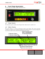
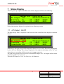
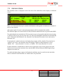
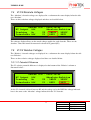
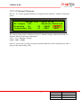
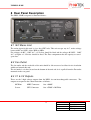
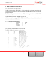
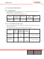
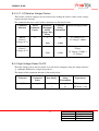
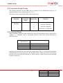
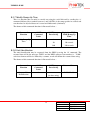
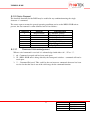
UMDPS2-1P10P
DPS2 –1P10P
Dual Output Digital
High Voltage Power Supply
This document supersedes all previous specifications. Photek accept no responsibility for
damage incurred if the customer does not follow the procedures outlined in this manual.
Photek Ltd
26 Castleham Road
St Leonards-on-Sea
East Sussex
United Kingdom
TN38 9NS
Telephone
+44 1424 850555
Facsimile
+44 1424 850051
E-mail:
[email protected]
Issue 2
15th September 2014
1
User Manual
Issue:
Date:
Author:
UMDPS2-1P10P
2
15-9-2014
P Simpson
UMDPS2-1P10P
Contents
1
SAFETY:-
4
2
HIGH VOLTAGE CONNECTION NOTES:-
4
3
DPS2-1P10P - DESCRIPTION
5
4
DPS2-1P10P FEATURES
6
4.1 Independent or Tracking Operating Modes.
4.1.1
Independant
4.1.2
Tracking
6
6
6
4.2
Manual Adjustment
7
4.3
Saved Operating Conditions
7
4.4
Automatic ‘Ramp-Up’.
7
4.5
Interlock Functions to inhibit high voltage outputs
8
4.6
Audible Alarm with indicated alarm condition.
8
5
INITIAL SETUP
9
6
FRONT PANEL DESCRIPTION
6.1
Power Switch
11
6.2
Status Display
11
6.3
Front Panel Controls
12
7
STATUS DISPLAY
7.1
HT Output - On/Off
14
7.2
Tracking – On/Off
15
7.3
Interlock Status
16
7.4
V1/V2 Absolute Voltages
17
11
14
2
User Manual
Issue:
Date:
Author:
UMDPS2-1P10P
2
15-9-2014
P Simpson
UMDPS2-1P10P
7.5 V1/V2 Relative Voltages
7.5.1
V1 Potential Difference
7.5.2
V2 Potential Difference
17
17
18
8
REAR PANEL DESCRIPTION
19
8.1
IEC Mains Inlet
19
8.2
Fan Outlet
19
8.3
V1 & V2 Outputs
19
8.4
GND Terminal
20
8.5
Interlock Connector
20
8.6
D.C Output Fuses
21
8.7
RS-232 Connector
21
9
RS-232 SERIAL INTERFACE
22
9.1 Serial Link Configuration
9.1.1
Configuration Summary:-
22
22
9.2
22
DPS2-1P10P Serial Commands
9.3 Command & Data Format
9.3.1
Tracking On/Off
9.3.2
Front, Rear and Screen Absolute Voltage Control
9.3.3
Front, Rear and Screen Relative Voltage Control
9.3.4
High Voltage Power On/Off
9.3.5
Interlocks Enable/Disable
9.3.6
Interlock Status
9.3.7
Modify Ramp-Up Time
9.3.8
Unit Identification
9.3.9
Status Request
9.3.10
Command Acknowledgement
10
DPS2-1P10P SPECIFICATIONS
10.1
Mechanical:
23
23
23
24
24
25
25
26
26
27
27
28
28
10.2
Electrical:
10.2.1
Mains Supply
10.2.2
High Voltage Outputs
28
28
28
3
User Manual
Issue:
Date:
Author:
UMDPS2-1P10P
2
15-9-2014
P Simpson
UMDPS2-1P10P
1 Safety:The high voltage modules contained within the DPS2-1P10P has a maximum current capability
as follows:• V1
(1kV module)
2mA
• V2
(10kV module)
250uA
The maximum output energy that can be delivered by this module is limited to less than 4 joules
for user safety,
Warning:- If a large capacitive load is connected across the output, the energy stored by
this external capacitor may exceed this non-fatal limit.
Energy Stored By Capacitor = ½ CV2 joules
In order to avoid any corona discharge: - Under no circumstances should a high voltage output
be run at a voltage higher than 5kV in air without some insulation material encapsulating the
high voltage connection.
2 High Voltage Connection Notes:All High Voltage connections must be made before applying power to this unit.
The connectors supplied with this unit are 12kV rated high voltage SHV BNC connectors. Care
should be taken to ensure that correct connections have been made before power is applied to
this unit.
User terminated connections must be carried out with adequate precautions to ensure safety of
both user and equipment
The following precautions should be observed for connections made by the user: 1. All wires must have an adequate voltage rating for the high voltage that they will
carry.
2. All wires utilised in a vacuum chamber must be suitable for this application.
1. All wires should be continuous and connected to the DPS unit SHV BNC plug at one
end and the Channel plate detector SHV BNC plug at the other end. These wires
should not be ‘wired inline’, i.e. joined.
2. Mechanical strength of connections should be ensured with adequate strain relief to
ensure reliable operation and extended life of the connections.
3. Connections should be insulated with suitable insulation material, such as heatshrinkable insulation tubing, or a suitable silicon compound may be used to
encapsulate the connections.
4
User Manual
Issue:
Date:
Author:
UMDPS2-1P10P
2
15-9-2014
P Simpson
UMDPS2-1P10P
3
DPS2-1P10P - Description
The DPS2-1P10P is a universal A.C. mains powered digital control unit designed to apply the
high voltage required for an imaging detector system.
The DPS2-1P10P unit incorporates two high voltage modules which allow for independent
voltage control for an MCP device with a screen.
This unit may be used in conjunction with MCP gating modules such as Photeks GM-MCP.
Exposure and Timing control may be supplied by units such as Photeks IGC2 low jitter
Intensifier Gating Controller.
The DPS2-1P10P may be controlled from a PC using ASCII commands (detailed later in this
manual). The only external requirement for computer control is an unused serial port on the
computer and a simple communication suite such as windows Hyperterminal.
The DPS2-1P10P may be incorporated into the users' software suite as all bi-directional control
codes and protocols utilise ASCII characters. These codes and protocols are included later in this
manual.
The DPS2-1P10P can be controlled from 6 push-button keys and a rotary encoder and
information on the operating conditions is displayed on a 4 line x 40-character alphanumeric
liquid crystal display located on the front panel of the unit.
The DPS2-1P10P has 2 High Voltage outputs via high voltage BNC connectors located on the
rear panel of the unit. The high voltage modules contained in this unit are:1.
V1
0 to +1000V
2.
V2
0 to +10000V
The DPS2-1P10P outputs may be controlled either in output tracking mode or independent
output adjustment mode.
The high voltage outputs are displayed in both ‘Absolute’ voltages and also with ‘Relative’
voltages for each electrode of the VID module.
The DPS2-1P10P does not provide any image acquisition or image processing functions.
5
User Manual
Issue:
Date:
Author:
UMDPS2-1P10P
2
15-9-2014
P Simpson
UMDPS2-1P10P
4 DPS2-1P10P Features
The DPS2-1P10P has been designed to supply two output voltages to an Imaging Detector. The
DPS2-1P10P offers the facility to vary the gain of the detector and may be incorporated into a
synchronised exposure system.
The outputs from the DPS2-1P10P are both positive and supply 2 tracking electrode voltages in
order to operate the MCP independantly while maintaning constant potential differences on the
other electrode.
This unit can be used in several modes of operation controlled by either computer control or
manual editing via the front panel controls.
The features and possible operating modes for the DPS2-1P10P are detailed below.
4.1 Independent or Tracking Operating Modes.
The DPS2 incorporates a tracking function which may be enabled or disabled by the ‘Track’
key on the front panel or via the ‘T1’ or ‘T0’ commands from a computer.
4.1.1 Independant
If Tracking is disabled any output may be controlled independantly within its pre-programmed
limits. The other 2 outputs will remain at their absolute value, although their relative potentials
may change.
In ‘Independent’ mode the outputs may be adjusted to give negative potential differences and the
unit will operate as a standard multiple output high voltage bench power supply. In this mode
DPS2 may be used for functions other than standard imaging device operation.
4.1.2 Tracking
With ‘Tracking’ enabled adjustments made to V1 will automatically track to maintain previously
set potential differences on the other electrodes.
The tracking function operates as follows:
The voltage applied to the V1 is automatically added to the voltage on V2 so that the
DPS2 maintains a constant voltage and the ‘Gap’ potential is maintained.
Adjustments to the V2 output will only adjust the V2 – V1 ‘Gap’ potential, it is not
added to the voltage on V1.
6
User Manual
Issue:
Date:
Author:
UMDPS2-1P10P
2
15-9-2014
P Simpson
UMDPS2-1P10P
4.2 Manual Adjustment
Any electrode may be manually adjusted at any time by selecting the electrode and using the
adjust control to either increase or decrease the voltage.
All outputs will adjust with 1V resolution. The speed that the voltage may be adjusted in
manual mode is proportional to the speed that the adjust control is turned, however the the
modules contained within the DPS unit are limited to a controlled slow rate of change to
avoid abrupt changes on the detector. The rate of change is related to the specific module and
will be in the region of 0 to 100% in a time between 400 and 800ms.
4.3 Saved Operating Conditions
The DPS2 automatically saves all of the operating conditions and the last set voltages for
each output.
Once the desired operating voltages have been input they may be enabled/disabled just by
pressing the ‘Run’ key, this will ramp all voltages up over the preset ‘Ramp-Up’ time.
The DPS2 saves all of the control settings including Tracking and Interlock functions. If
either or both interlocks have been enabled during the last operation of the DPS2 then they
will automatically be enabled after power up.
If the unit is being operated via computer control then it is advisable that all desired setup
conditions are transmitted to the DPS2 during initialisation.
4.4 Automatic ‘Ramp-Up’.
As the DPS2 contains 2 independent high voltage power supplies an automatic ‘Ramp-Up’
feature has been incorporated to ensure that all voltages are applied to the intensifier in a safe
and controlled way.
When the ‘Run’ key is pressed or a ‘P1’ command is received from a computer the DPS2
will power up the HT power supplies and perform an automatic increment routine over the
pre-programmed ‘Ramp’ time (between 1 and 240 seconds). The factory default ‘Ramp’ time
is set to 5 seconds. This automatic increment raises the voltage in 1% steps.
When the ‘Run’ key is pressed to power down the high voltage or a ‘P0’ command is
received the DPS2 will ‘Ramp-Down’ the high voltage in 10% steps during 100
milliseconds. This is a controlled emergency off function so that electrode limit voltages are
not exceeded during power down, but still allows the high voltage to be shutdown quickly.
If an electrode voltage adjustment command is received from a computer the DPS2 will
perform an automatic increment/ decrement to the new set levels over the pre-programmed
‘Ramp’ time. This is not an emergency off function, so reduction of voltages ramps over the
same time period as an increase.
7
User Manual
Issue:
Date:
Author:
UMDPS2-1P10P
2
15-9-2014
P Simpson
UMDPS2-1P10P
During any adjustment or Ramp-Up function the DPS2 will emit an audible tone that
continues at 0.5s intervals until the voltages have reached their new values. The last tone will
be a long tone to indicate the adjustment has been completed.
4.5 Interlock Functions to inhibit high voltage outputs
The DPS2 has 2 interlock inputs that may be enabled either independantly or together to
provide a system safety high voltage over-ride. Both interlocks may be disabled if not
required.
To enable the interlocks the I/L key may be pressed repeatedly until the desired interlocks
have been enabled or the ‘I’ command may be used from a computer.
The interlocks are TTL inputs that must be grounded to allow the high voltage to turn on. If
the input is open circuit the interlock will be active and the DPS2 will inhibit the high
voltage function.
4.6 Audible Alarm with indicated alarm condition.
The interlock inputs are constantly monitored by the DPS2 firmware and if an interlock
occurs the high voltage will be automatically powered down and an audible alarm will occur.
The DPS2 status display will indicate which Interlock function triggered the over-ride, IL1 =
interlock 1 and IL2 = interlock 2.
To cancel the alarm press any of the front panel keys. This will cancel the alarm but will not
re-enable the high voltage. It is advised that the user investigate the interlock before reenabling the high voltage.
Once the alarm has been cancelled the DPS2 will function normally, however if the interlock
is still active and enabled the DPS2 will not allow the high voltage to be turned on. Any
press of the ‘Run’ key will emit an audible tone to indicate there is still an active interlock.
8
User Manual
Issue:
Date:
Author:
UMDPS2-1P10P
2
15-9-2014
P Simpson
UMDPS2-1P10P
5 Initial Setup
For the initial setup of a VID system manual control should be used. A safe procedure is outlined
below: Ensure that all high voltage connections are terminated correctly prior to powering up the DPS2
unit.
After powering up the DPS2 the status display will briefly display the software details and date
of issue of the DPS2 unit.
The status display will then show the last operating conditions of the DPS2 the Ht Output ‘Off’
will flash to indicate the high voltage outputs are disabled. When powered down the DPS2 stores
the last settings and on power up it displays these ready to be enabled by a single press of the
‘Run’ key, for this reason the display actively displays that the outputs are off.
Ensure that Tracking is set to ‘On’, this is the default condition and is indicated on the status
display and also by the illuminated ‘Track’ key.
1. If tracking is ‘Off’ press the ‘Track’ key to turn it on.
If the Interlock functions are to be utilised ensure that the interlock conditions are satisfied and
enable the interlocks as follows.
2. Press the I/L key to cycle through the interlocks to select the desired setting.
All of the voltages of the DPS2 should be zeroed prior to a controlled power up of the VID.
3. Press and hold the ‘Reset’ key, an audible tone will be heard and all the high voltage outputs
will be reset to 0V.
4. Press the ‘Run’ key to power up the high voltage modules.
V2 is the first electrode to be adjusted so that the detector may be monitored and any excessive
signal can be observed and acted upon. Without voltages on the MCP there should be no signal
observed, any signal indicates a problem. The precise operating voltage may vary between
devices so please consult the documentation supplied with the detector.
5. Press the ‘V2’ key and adjust the voltage to the desired level.
Please refer to test documentation supplied with the detector to determine the precise operating
voltages that are required.
9
User Manual
Issue:
Date:
Author:
UMDPS2-1P10P
2
15-9-2014
P Simpson
UMDPS2-1P10P
6. Press the ‘V1’ key and adjust the voltage to the desired level.
Once an acceptable level of signal has been determined the DPS2 may be operated without
further adjustment. The High voltage settings will be remembered and may be safely powered up
and down by succesive presses of the ‘Run’ key.
7. To power down the detector press the ‘Run’ key.
10
User Manual
Issue:
Date:
Author:
UMDPS2-1P10P
2
15-9-2014
P Simpson
UMDPS2-1P10P
6
Front Panel Description
The front panel of the DPS2-1P10P is illustrated below: -
Photek Ltd :
HT Output Off
Tracking
On
V2
Interlocks Off
V1
DPS2-1P10P
Absolute:Relative
: 5800V : 5000V
: 800V : 800V
6.1 Power Switch
The illuminated power on/off switch will glow ‘Red’ when the unit is switched ‘On’.
6.2 Status Display
The status display is a 4 line by 40-character liquid crystal display. The current operating
conditions are displayed here. Manual modification of functions may be carried out using the 6
keys and tha ‘Adjust’ rotary control and by monitoring this display.
Relative Voltage Display
V2 to V1 ‘Gap Voltage’
V1 Potential Difference
V2 Absolute Voltage
V1 Absolute Voltage
Photek Ltd : DPS2-1P10P
HT Output Off
Absolute:Relative
Tracking
On
V2 : 5800V : 5000V
Interlocks Off
V1 : 800V : 800V
High Voltage Output On/Off Indicator
Voltage Tracking Indicator
Interlock Status Indicator
11
User Manual
Issue:
Date:
Author:
UMDPS2-1P10P
2
15-9-2014
P Simpson
UMDPS2-1P10P
Functions downloaded from the PC will be displayed on the unit status display when they are
implemented.
Under normal operating conditions the status display will indicate the current values of all
relevant functions: Output On/Off, Tracking On/Off, Interlocks status and the 2 output voltages
displayed in both absolute and relative potentials.
6.3 Front Panel Controls
The DPS2-1P10P may be operated under manual control via the 6 push-button keys. Each key is
annunciated with its function. The keys are colour coded to identify common operating
functionality.
There are 6 function keys as illustrated below: -
1. Track – The Track key is Orange and illuminates when active.
This allows the user to enable/disable the high voltage tracking function.
When tracking is enabled any voltage adjustment on the V1 will be applied to V2.
This includes both increments and decrements. The DPS2-1P10P will not allow
negative ‘gap voltages’ in tracking mode, i.e. the V1 can never exceed the V2
potential. The software programmed limits will be active to limit the maximum
voltages that may be set on each output.
When tracking is disabled each output may be adjusted independantly. In this
mode any output may be set to any value within its pre-programmed limits.
Negative gap potentials are possible in this mode of operation, i.e. V1 can exceed
the V2 potential.
2. V1/V2 – These keys are yellow and will illuminate when active.
These are edit functions which when pressed will allow for manual adjustment of
the related electrode voltage utilising the ‘Adjust’ control.
V1– This allows the V1 voltage to be modified.
V2 - This allows the V2 voltage to be modified.
12
User Manual
Issue:
Date:
Author:
UMDPS2-1P10P
2
15-9-2014
P Simpson
UMDPS2-1P10P
3. I/L – The Interlock key is orange and illuminates when active.
This key allows the interlock status required. There are 2 interlocks which may be
enabled either to be ‘Seperately On’ or ‘Both On’ or ‘Both Off’.
Consecutive presses of this key will cycle through the interlocks in the sequence
Interlocks Off, Interlock 1 On, Interlock 2 On, Interlocks On (both 1 and 2) and
then back to Interlocks Off
4. Reset – The ‘Reset’ key is orange and illuminates when active.
The Reset Key may be used to zero all outputs when the High Voltage outputs are
turned off. This allows the user to start at 0V on all electrodes and gradually
increase each electrode voltage individually.
5. Run – The ‘Run’ key is coloured red and illuminates when active.
This key is a toggle function for the High Voltage On/Off control i.e. each time
this key is pressed the high voltage power will be toggled to the opposite state.
There is an LED on this key that will illuminate when the hig voltage power is on.
This is also the case when the Intensifier power is turned on via the RS-232 link
4. Adjust – The ‘Adjust’ control is a rotary control for data editing.
When either of the voltage edit functions V1/V2 are selected the ‘Adjust’ control
may be used to increase or decrease the voltage on that electrode.
If the high voltage outputs are ‘On’ the adjustment of any electrode voltage is
dynamic and occurs in real time as the user adjusts the control. This approximates
to analogue control of the high voltage output selected.
If the high voltage outputs are ‘Off’ when adjustments are made the DPS2 will
use its pre-programmed ramp-up time when the ‘Run’ key is pressed to turn the
high voltage outputs on.
If the Tracking function is set to ‘On’ any adjustment of the V1 will be
automatically added to the V2 output. Any adjustment made to V2 only adjusts
V2. If at any time a limiting value is reached the DPS2 will emit an audible tone.
The DPS2 will not allow its pre-programmed gap voltages to be exceeded.
13
User Manual
Issue:
Date:
Author:
UMDPS2-1P10P
2
15-9-2014
P Simpson
UMDPS2-1P10P
7
Status Display
After the power up sequence the DPS2 status will be displayed similar to the following: -
Photek Ltd : DPS2-1P10P
HT Output Off
Absolute:Relative
Tracking
On
V2 : 5800V : 5000V
Interlocks Off
V1 : 800V : 800V
Each of the functions displayed is explained in the following sections.
7.1 HT Output - On/Off
The high voltage status is displayed on the left side of the second line of the display as indicated
below: -
Photek Ltd : DPS2-1P10P
HT Output Off
Absolute:Relative
Tracking
On
V2 : 5800V : 5000V
Interlocks Off
V1 : 800V : 800V
Immediately after power up the HT Output will always be set to ‘Off’. This will be highlighted
by the ‘Off’ text flashing. The voltages displayed on the right of the display will be the used
values, however no voltage will be present on the output connectors.
The ‘Run’ key must be pressed in order to turn the HT Outputs ‘On’. All outputs will be turned
on when the ‘Run’ key is pressed.
When the HT Outputs are ‘On’, the ‘Run’ key will illuminate.
14
User Manual
Issue:
Date:
Author:
UMDPS2-1P10P
2
15-9-2014
P Simpson
UMDPS2-1P10P
7.2 Tracking – On/Off
The Tracking function is displayed on the left side of the third line of the display as indicated
below: -
Photek Ltd : DPS2-1P10P
HT Output Off
Absolute:Relative
Tracking
On
V2 : 5800V : 5000V
Interlocks Off
V1 : 800V : 800V
When Tracking mode is ‘On’, the potential difference between V1 and V2 electrodes will be
automatically maintained during adjustment of the V1 electrode voltage. In this mode it is not
possible to set V1 higher than V2, and likewise it is not possible to set V2 lower than V1. The
DPS2 will not allow the outputs to exceed the pre-programmed maximum values.
When Tracking is ‘Off’, each electrode voltage may be set to any value within its preprogrammed limits. In this mode it is possible reverse bias the outputs of the DPS2 i.e. The V1
voltage may exceed the V2 voltage, and the V2 voltage may be adjusted below the V1 voltage.
The DPS2 will not allow the outputs to exceed the pre-programmed maximum values.
The ‘Track’ key must be pressed to toggle between ‘Tracking On’ and ‘Tracking Off’
(Independent) control modes. When Tracking is ‘On’ the ‘Track’ key will illuminate.
15
User Manual
Issue:
Date:
Author:
UMDPS2-1P10P
2
15-9-2014
P Simpson
UMDPS2-1P10P
7.3 Interlock Status
The interlock status is displayed on the left side of the fourth line of the display as indicated
below: -
Photek Ltd : DPS2-1P10P
HT Output Off
Absolute:Relative
Tracking
On
V2 : 5800V : 5000V
Interlocks Off
V1 : 800V : 800V
There are 2 interlocks that may be enabled individually, both together or both may be disabled if
they are not required.
After power up the last used setting for the interlocks will be automatically enabled.
The interlock inputs are located on the 25-Way D Socket mounted on the rear panel of the DPS2.
To enable/disable the interlocks the ‘I/L’ key must be pressed repeatedly until the desired setting
is displayed. Successive presses of the ‘I/L’ key will cycle through the interlocks in the following
order – Interlocks Off, Interlock 1 On, Interlock 2 On, Interlocks On (both 1 &2), then back to
Interlocks Off.
If an interlock is enabled and active the high voltage outputs will be disabled. If an interlock is
‘enabled’ and ‘active’ the interlock status will change to indicate which interlock is active,
‘Inhibit - IL1’ – means Interlock 1 is active, or ‘Inhibit – IL2’ means Interlock 2 is active.
If either interlock is enabled then it will be active if the input is open circuit, this ensures that
broken wires between the interlock driver and the DPS2 will not allow the DPS2 high voltage
outputs to be turned on.
To enable the high voltage outputs, the Interlock conditions must be satisfied or the interlocks
must be disabled. If the interlocks are disabled the is no protection.
16
User Manual
Issue:
Date:
Author:
UMDPS2-1P10P
2
15-9-2014
P Simpson
UMDPS2-1P10P
7.4 V1/V2 Absolute Voltages
The ‘Absolute’ electrode voltages are displayed in a column on the status display below the title
text ‘Absolute’.
There are three absolute voltages displayed and these are detailed below.
Photek Ltd : DPS2-1P10P
HT Output Off
Absolute:Relative
Tracking
On
V2 : 5800V : 5000V
Interlocks Off
V1 : 800V : 800V
The voltages displayed here are the actual voltages applied to each electrode. These are the
absolute values that would be measured referenced to ground (0V).
7.5 V1/V2 Relative Voltages
The ‘Relative’ electrode voltages are displayed in a column on the status display below the title
text ‘Relative’.
There are three relative voltages displayed and these are detailed below.
7.5.1 V1 Potential Difference
The V1 relative potential difference is displayed at the bottom of the ‘Relative’ column as
illustrated below: -
Photek Ltd : DPS2-1P10P
HT Output Off
Absolute:Relative
Tracking
On
V2 : 5800V : 5000V
Interlocks Off
V1 : 800V : 800V
As the V1 electrode is biased between 0V and the voltage set by the DPS2 the voltage indicated
here is the same as the ‘Absolute’ voltage indicated for the V1 electrode.
17
User Manual
Issue:
Date:
Author:
UMDPS2-1P10P
2
15-9-2014
P Simpson
UMDPS2-1P10P
7.5.2 V2 Potential Difference
The V2 – V1 relative potential difference is displayed in the ‘Relative’ column as illustrated
below: -
Photek Ltd : DPS2-1P10P
HT Output Off
Absolute:Relative
Tracking
On
V2 : 5800V : 5000V
Interlocks Off
V1 : 800V : 800V
The voltage displayed here will always be the V1 Absolute voltage subtracted from the V2
Absolute voltage. In the above illustration: (V2 ) - (V1) = (Relative Voltage)
5800V - 800V = 5000V
If the V1 exceeds the V2 voltage a negative potential difference will be displayed here (this is
only possible with tracking ‘Off’).
18
User Manual
Issue:
Date:
Author:
UMDPS2-1P10P
2
15-9-2014
P Simpson
UMDPS2-1P10P
8 Rear Panel Description
The DPS2-1P10P rear panel is illustrated below: -
8.1 IEC Mains Inlet
The mains input for this unit is via a fused IEC inlet. This unit accepts any A.C. mains voltage
between 90V and 250V, either 50Hz or 60Hz.
For voltages of 90V - 120V A.C. a 2.5A fuse should be fitted and for voltages 0f 220V - 240V
A.C. or higher a 1.25A fuse should be fitted. The Fuse compartment has the capacity to store 1
spare fuse.
8.2 Fan Outlet
The fan outlet and the underside of the unit should be left uncovered to allow for air circulation
within and around this unit.
The air intake is via slots located on the bottom of the unit and air is expelled from the Fan outlet
mounted on the rear panel.
8.3 V1 & V2 Outputs
These are the 2 high voltage outputs from the DPS2 via non-interchangeable connectors. The
outputs correspond to the control functions as follows: MCPOut
MHV Connector
0 to +1000V
Screen
SHV Connector
0 to +5500V + MCPOut
19
User Manual
Issue:
Date:
Author:
UMDPS2-1P10P
2
15-9-2014
P Simpson
UMDPS2-1P10P
8.4 GND Terminal
This is an extra earthing point provided if a large earth connection is required from the
customers vacuum chamber metalwork to the DPS2 unit.
8.5 Interlock Connector
This 25-Way D-Type Socket contains both interlocks and 3 low voltage power supply for the
operation of peripheral interface units.
The interlock connections are TTL inputs that are pulled high. To use an interlock function a
grounded connection must be supplied that indicates that the interlock is safe and allow the high
voltage to be powered on. If an interlock is enabled and left open circuit it will disable the high
voltage outputs from this unit and sound an alarm.
The Functions of this connector are indicated below: -
(View as seen looking at the rear panel)
Pin No.
4, 17
1, 14
2, 15
3, 16
5, 6, 7, 8, 9, 10,
18, 19, 20, 21,
22, 23, 24, 25
11
12
25-Way D-Type Socket
Function
No Connection
+12V @ 0.25A Power Output (See Note)
+5V @ 2A Power Output (See Note)
-12V @ 0.25A Power Output (See Note)
0V
Interlock 2 Input
Interlock 1 Input
Note: - Each power output is fitted with a fuse on the rear panel of the DPS2-1P10P unit, each
fuse is a 5x20mm anti-surge (T) rated at the output current maximum.
20
User Manual
Issue:
Date:
Author:
UMDPS2-1P10P
2
15-9-2014
P Simpson
UMDPS2-1P10P
8.6 D.C Output Fuses
The DPS2 provide 3 output supply rails which may be used by the customer to power small
quantities of peripheral electronics associated with the DPS2 system such as interlock drive
electronics. In order to ensure that excessive current drawn from these supply rails does not
affect the DPS2 primary function each output rail has been fitted with an accessible fuse located
on the rear panel of the DPS2 unit. The output voltages and the fuse rating or maximum
allowable currents are printed on the panel next to each fuse.
8.7 RS-232 Connector
This is an asynchronous serial communication port operating at a fixed baud rate of 19200. This
enables the DPS2-1P10P to be controlled from a standard PC by means of ASCII control
characters and codes.
The DPS2-1P10P RS-232 uses a 3 wire system (transmit and receive), handshaking is
implemented in software for confirmation of valid control codes.
A full listing of codes and protocols are listed in the software interface section of this manual.
The RS-232 connector is a 9-Way D-Type Plug. Pin-out functions are listed below: -
(View as seen looking at the rear panel)
9 Way D-type plug
Pin No.
Function
Pin 2
Transmit data
Pin 3
Receive data
Pin 5
Ground/ 0V
21
User Manual
Issue:
Date:
Author:
UMDPS2-1P10P
2
15-9-2014
P Simpson
UMDPS2-1P10P
9 RS-232 Serial Interface
9.1 Serial Link Configuration
The RS-232 utilised by the DPS2-1P10P is a 3-wire interface for asynchronous transmission and
reception of data. The interface utilises TD (Transmit Data), RD (Receive Data) and Gnd from
the RS-232 protocol.
The Baud rate for communication is fixed at 19200; this is programmed into the DPS2-1P10P
and cannot be modified.
The Data format is No Parity, 8 Data bits and 1 stop bit.
All data transmitted to or from the DPS2-1P10P is in ASCII format. Commands take the form of
letters and variables are ASCII numbers.
9.1.1 Configuration Summary:Baud Rate
Parity
Data Bits
Stop Bits
=
=
=
=
19200
No
8
1
9.2 DPS2-1P10P Serial Commands
The DPS2-1P10P serial commands are listed below: a
b
il
8bit
8bit
0-3
fa
ra
fr
rr
p
t
xf
xr
u
z
0-1000
0-10000
0-1000
0-10000
0,1
0,1
0-1000
0-10000
0-240
EEPROM address
EEPROM data byte
0 = Interlocks Off
1= Interlock 1 On
2 = Interlock 2 On
3 = Both Interlocks On
V1 absolute voltage
V2 absolute voltage
V1 relative voltage
V2 relative voltage
HT Power Off, On
Tracking Off/On
V1 Gap limit
V2 Gap limit
High Voltage Ramp-Up Time
status request
22
User Manual
Issue:
Date:
Author:
UMDPS2-1P10P
2
15-9-2014
P Simpson
UMDPS2-1P10P
9.3 Command & Data Format
9.3.1 Tracking On/Off
The Tracking function may be turned on or off by the computer using the single character ‘t’
command followed by a single integer 0 or 1.
The format of this command function is illustrated below: Command
Function
ASCII
Command
Letter
ASCII Integer
Data String
Command
String
Transmitted
Instruction
Equivalence
t
0
t0
Tracking = Off
1
t1
Tracking = On
Modify
Tracking
9.3.2 V1, V2 Absolute Voltage Control
Each of the electrode voltages may be adjusted by sending the absolute values of the voltage
required on that electrode.
The command characters coded to these functions are illustrated below: Command
Function
ASCII
Comma
nd
Letters
Minimum/
Maximum
ASCII Integer
Data String
Command
String
Transmitte
d
Instruction Equivalence
Modify
Absolute
Voltage of V1
fa
1
fa1
V1 Voltage 1V
Modify
Absolute
Voltage of V2
V1 Voltage = 2000V
ra
2000
fa2000
1
ra1
V2 Voltage = 1V
V2 Voltage = 7500V
7500
ra7500
23
User Manual
Issue:
Date:
Author:
UMDPS2-1P10P
2
15-9-2014
P Simpson
UMDPS2-1P10P
9.3.3 V1, V2 Relative Voltage Control
Each of the electrode voltages may be adjusted by sending the relative values of the voltage
required on that electrode.
The command characters coded to these functions are illustrated below: Command
Function
ASCII
Command
Letters
Minimum/
Maximum
ASCII
Integer Data
String
Command
String
Transmitted
Instruction Equivalence
Modify
Relative
Voltage of V1
fr
1
fr1
V1 Voltage = 1V
Modify
Relative
Voltage of V2
V1 Voltage = 1000V
1000
fr1000
1
rr1
2500
rr2500
rr
V2 Voltage = 1V + V1
Voltage
V2 Voltage = 2500V +
V1 Voltage
9.3.4 High Voltage Power On/Off
The high voltage power may be turned on or off by the computer using the single character
‘p’ command followed by a single integer 0 or 1.
The format of this command function is illustrated below: Command
Function
Modify Power
ASCII
Command
Letter
ASCII Integer
Data String
Command
String
Transmitted
Instruction
Equivalence
p
0
p0
HT Power = Off
1
p1
HT Power = On
24
User Manual
Issue:
Date:
Author:
UMDPS2-1P10P
2
15-9-2014
P Simpson
UMDPS2-1P10P
9.3.5 Interlocks Enable/Disable
The interlock functions for the DPS2 may be enabled in any combination using the ‘il’
command followed by a single integer 0, 1, 2 or 3.
The format of this command function is illustrated below: -
Command
Function
ASCII
Command
Letter
Valid ASCII
Integer Data
Equivalent DPS2-1P10P
Function
Enable/Disable
Interlocks
il
0
Interlocks 1 & 2 Disabled
1
Interlock 1 Enabled
2
Interlock 2 Enabled
3
Interlocks 1 & 2 Enabled
9.3.6 Interlock Status
When controlling interlocks from software the status of the interlocks may be requested by
sending a “z” command. The 5th data block returned is the status of the interlocks as
indicated below: Interlock Status
Data Returned
0
1
2
3
Interlock Status Data Meaning
Interlocks Off
Interlock/s On and Satisfied
Interlock 1 On and Unsatisfied
Interlock 2 On and Unsatisfied
Satisfying an interlock does not cancel the audible alarm, this is to ensure that intermittent
interlock faults do not go undetected. The interlock alarm audible tone will be cancelled by
pressing any of the front panel buttons or, under software control, the next time the High
Voltage is turned on.
25
User Manual
Issue:
Date:
Author:
UMDPS2-1P10P
2
15-9-2014
P Simpson
UMDPS2-1P10P
9.3.7 Modify Ramp-Up Time
This is a function that can only be carried out using the serial link and by sending the ‘u’
command followed by a number between 1 and 240. This is the ramp up time in seconds and
can therefore be adjusted between 1second and 240seconds (4 minutes)
The format of this command function is illustrated below: -
Command
Function
ASCII
Command
Letter
ASCII Integer
Data String
Equivalent DPS21P10P Ramp Up
Time
Modify Ramp-Up
Time
u
1
1 second
30
30 seconds
240
240 seconds
9.3.8 Unit Identification
The unit identification may be requested from the DPS2 by using the ‘id’ command. The
returned data will be the unit type ‘DPS2’ and the DPS2 software issue number i.e. ‘V1.00’.
each data element will be de-limited by a comma, an ok will follow the returned data string.
The format of this command function is illustrated below: -
Command
Function
ASCII
Command
Letter
ASCII Integer
Data String
Returned Data
Request Unit
Identification
id
-
DPS2,V1.00,
(no data string)
26
User Manual
Issue:
Date:
Author:
UMDPS2-1P10P
2
15-9-2014
P Simpson
UMDPS2-1P10P
9.3.9 Status Request
The interlock functions for the DPS2 may be enabled in any combination using the single
character ‘z’ command.
The status request streams the general operating conditions active on the DPS2-1P10P unit at
present, the data returned is coma delimited and is listed below: Command
z
9.3.10
Function
Request Status
Data Returned
V1 Absolute Voltage
V2 Absolute Voltage
Interlock Enable
Interlock Status
Tracking On/Off
High Voltage On/Off
Ramp Up Time
Command Acknowledgement
When a serial command is received it is acknowledged with either ‘ok’, ‘!E’ or ‘??’.
1. ok – Command accepted and has been acted upon.
2. !E – DPS2-1P10P unit is being edited by the front panel switches – command will not be
acted upon.
3. ?? – Command Rejected. This could be that an incorrect command character has been
received or that the data is out of the valid range for the command function.
27
User Manual
Issue:
Date:
Author:
UMDPS2-1P10P
2
15-9-2014
P Simpson
UMDPS2-1P10P
10 DPS2-1P10P Specifications
10.1
Mechanical:
DPS2-1P10P Size:
258 x 265 x 110mm (Maximum Extents)
DPS2-1P10P Weight:
≈3.6Kg
Panel Colour:
Umbra Grey
(RAL7022)
Case Colour:
Pebble Grey
(RAL7032)
Bezel Colour:
Stone Grey
(RAL7030)
10.2
Electrical:
10.2.1
Mains Supply
Supply Voltage:
Universal 90-260V 50/60Hz
Fuse Rating Required:
110V/120V
2.5Amp
220V/240V
1.25Amp
10.2.2
High Voltage Outputs
The DPS2-1P10P is fitted with 2 High voltage modules. When the ‘Run’ switch is
illuminated these high voltage D.C. output voltages will be present on the high voltage BNC
sockets on the rear of the unit.
Maximum
Output
Voltage
Maximum
Output
Current
Full Load
Ripple
V2
+1kV
2mA
200mV
V1
+10kV
250uA
1.6V
© Photek Ltd. September 2014
Any unauthorised adjustment or modification to this unit will void all warranties and will only be supported
at Photeks discretion.
Photek reserves the right to amend general information contained in this manual without prior notice.
28
User Manual
Issue:
Date:
Author:
UMDPS2-1P10P
2
15-9-2014
P Simpson