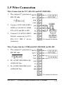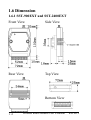
1
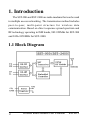
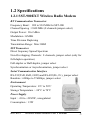
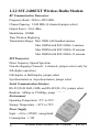
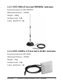
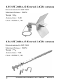
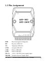
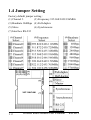
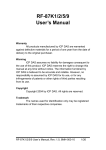
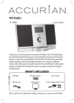
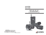
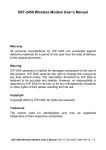
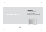
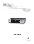
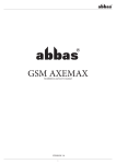
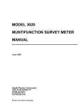
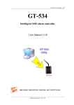
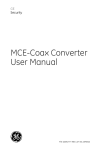
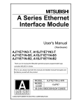
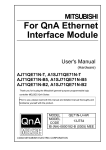
Wireless Radio Modem
User’s Manual
Warranty
All products manufactured by ICP DAS are warranted
against defective materials for a period of one year from the date
of delivery to the original purchaser.
Warning
ICP DAS assume no liability for damages consequent to
the use of this product. ICP DAS reserves the right to change this
manual at any time without notice. The information furnished by
ICP DAS is believed to be accurate and reliable. However, no responsibility is assumed by ICP DAS for its use, nor for any infringements of patents or other rights of third parties resulting from
its use.
Copyright
Copyright 1999 by ICP DAS. All rights are reserved.
Trademark
The names used for identification only maybe registered
trademarks of their respective companies.
Rev:B1.2
Date:2001-11
Wireless Radio Modem User’s Manual
1
Table of Contents
1. Introduction.....................................................4
1.1 Block Diagram ...........................................4
1.2 Specifications .............................................5
1.2.1 SST-900EXT Wireless Radio Modem .......... 5
1.2.2 SST-2400EXT Wireless Radio Modem ........ 6
1.2.3 SST-900A External 900MHz Antenna ......... 7
1.2.4 SST-2400A-3 External 2.4GHz Antenna ..... 7
1.2.5 SST-2400A-12 External 2.4GHz Antenna ... 8
1.2.6 SST-2400A-13 External 2.4GHz Antenna ... 8
1.3 Pin Assignment ..........................................9
1.4 Jumper Setting .........................................10
1.5 Wire Connection ...................................... 11
1.6 Dimension ................................................14
1.6.1 SST-900EXT and SST-2400EXT ............... 14
1.6.2 DIN-RAIL Mounting .................................. 15
1.6.4 Pannel Mounting......................................... 16
2 Configuration .................................................17
2.1 Full-duplex and Half-duplex ....................17
2.2 Synchronous and Asynchronous ..............18
2.3 Configuration Select ................................19
2.4 Operation Mode 1 ....................................20
2
Wireless Radio Modem User’s Manual
Rev:B1.2
2.5 Operation Mode 2 ....................................21
2.6 Operation Mode 3 ....................................22
3 Application......................................................23
3.1 Peer-to-Peer Communication...................23
3.2 Asynchronous Connection .......................24
3.3 Multiple PCs Communication..................25
3.4 Connect I-7000 Modules .........................26
3.5 Communication Bridge............................27
3.6 Network Communication .........................28
Rev:B1.2
Wireless Radio Modem User’s Manual
3
1. Introduction
The SST-900 and SST-2400 are radio modems that can be used
in multiple access networking. The transmission method includes
peer-to-peer, multi-point structure for wireless data
communication. Based on direct sequence spread spectrum and
RF technology operating in ISM bands, 902-928Mhz for SST-900
and 2426-2458MHz for SST-2400.
1.1 Block Diagram
4
Wireless Radio Modem User’s Manual
Rev:B1.2
1.2 Specifications
1.2.1 SST-900EXT Wireless Radio Modem
RF Communication Transceiver
Frequency Band : 909 to 924 MHz for SST-900
Channel Spacing : 2.048 MHz (8 channels jumper select)
Output Power : 20±2 dBm
Modulation : GMSK
Time Division Duplexing
Transimition Range : Max 300M
SST Transceiver
Direct Sequency Spread Spectrum
Non-Overlapping Channels : 8 channels, jumper select (only for
full-duplex operation)
Full-duplex or Half-duplex, jumper select
Synchronization or Asynchronization, jumper select
Serial Communication Interface
RS-232(TxD, RxD, GND) and RS-485(D+, D-), jumper select
Baudrate : 600bps to 57600bps, jumper select
Environment
Operating Temperature : 0°C to 50°C
Storage Temperature : -30°C to 70°C
Power Supply
Input : +10 to +30VDC, unregulated
Consumption : 1.5W
Rev:B1.2
Wireless Radio Modem User’s Manual
5
1.2.2 SST-2400EXT Wireless Radio Modem
RF Communication Transceiver
Frequency Band : 2426 to 2458 MHz
Channel Spacing : 2.048 MHz (8 channels jumper select)
Output Power : 20±2 dBm
Modulation : GMSK
Time Division Duplexing
Transimition Range : Max 300M with bundled antenna
Max 1000M with SST-2400A-3 antenna
Max 5000M with SST-2400A-12 antenna
Max 5000M with SST-2400A-13 antenna
SST Transceiver
Direct Sequency Spread Spectrum
Non-Overlapping Channels : 8 channels, jumper select (only for
full-duplex operation)
Full-duplex or Half-duplex, jumper select
Synchronization or Asynchronization, jumper select
Serial Communication Interface
RS-232(TxD, RxD, GND) and RS-485(D+, D-), jumper select
Baudrate : 600bps to 57600bps, jumper select
Environment
Operating Temperature : 0°C to 50°C
Storage Temperature : -30°C to 70°C
Power Supply
Input : +10 to +30VDC, unregulated
Consumption : 1.5W
6
Wireless Radio Modem User’s Manual
Rev:B1.2
1.2.3 SST-900A External 900MHz Antenna
External antenna for SST-900EXT
Maximum Distance : 1000M
Weight : 1000g
Antenna Gain : 5dB
Cable : RG58C/U, 4M
1.2.4 SST-2400A-3 External 2.4GHz Antenna
External antenna for SST-2400
Maximum Distance : 1000M
Weight : 150g
Antenna Gain : 3dB
Cable : RG58A/U, 1M
Rev:B1.2
Wireless Radio Modem User’s Manual
7
1.2.5 SST-2400A-12 External 2.4GHz Antenna
External antenna for SST-2400
Maximum Distance : 5000M
Weight : 850g
Antenna Gain : 12dB
Cable : RG58A/U, 1M
1.2.6 SST-2400A-13 External 2.4GHz Antenna
External antenna for SST-2400
Maximum Distance : 5000M
Weight : ???g
Antenna Gain : ??dB
Cable : RG58A/U, 1M
8
Wireless Radio Modem User’s Manual
Rev:B1.2
1.3 Pin Assignment
DSR
RX
TX
GND
(Y)D+
(G)D(R)+Vs
(B)GND
Rev:B1.2
Reserved signal of diagnostic
Receive of RS-232
Transimit of RS-232
Ground of RS-232
Data+ of RS-485
Data- of RS-485
+10 to +30V DC power supply input
Ground of power supply input
Wireless Radio Modem User’s Manual
9
1.4 Jumper Setting
Factory default jumper setting :
(1) Channel 3
(2) Frequency 915.968/2439.936MHz
(3) Baudrate 9600bps (4) Full-duplex
(5) Slave
(6) Synchronous
(7) Interface RS-232
10
Wireless Radio Modem User’s Manual
Rev:B1.2
1.5 Wire Connection
Wire Connection for PC’s RS-232 and SST-900/2400 :
1. The jumper(7) position in
RS-232 side
2. Connect SST-900/2400’s
GND to CA-0910’s GND,
TX to TX and RX to RX.
3. Connect CA-0910’s DB-9
female connector to PC’s
RS-232 DB-9 male
connector.
Wire Connection for I-7000 and SST-900/2400 via RS-485
1. The jumper(7) position in
RS-485 side.
2. D+ of SST-900/2400 to D+
of RS-485 bus.
3. D- of SST-900/2400 to Dof RS-485 bus.
Rev:B1.2
Wireless Radio Modem User’s Manual
11
Connect SST-900EXT with SST-900A
Connect SST-2400EXT with SST-2400A-3
12
Wireless Radio Modem User’s Manual
Rev:B1.2
Connect SST-2400EXT with SST-2400A-12
Connect SST-2400EXT with SST-2400A-13
Rev:B1.2
Wireless Radio Modem User’s Manual
13
1.6 Dimension
1.6.1 SST-900EXT and SST-2400EXT
Front View
Side View
Rear View
Top View
Bottom View
14
Wireless Radio Modem User’s Manual
Rev:B1.2
Antenna of
SST-2400EXT
Antenna of
SST-900EXT
1.6.2 DIN-RAIL Mounting
Rev:B1.2
Wireless Radio Modem User’s Manual
15
1.6.4 Pannel Mounting
16
Wireless Radio Modem User’s Manual
Rev:B1.2
2 Configuration
2.1 Full-duplex and Half-duplex
Full-duplex is to transimit and receive data at the same
time, and half-duplex is to transimit and receive data at seperate
time. While using full-duplex mode, only peer-to-peer operation
is available. For work in multi-point operation, half-duplex is the
only choice.
While working in full-duplex mode, one of the two communication modules is set as master and the other is set as slave.
And both modules have same baudrate, frequency and channel
select.
While working in half-duplex mode, the all modules have
the same configuration. The baudrate and frequency select need
all the same, and all modules select slave mode. The channel select is invalid for half-duplex mode. In half-duplex mode, only
one module may transimit at the same time. If more than one module transimit data at the same time, the received data is not correct.
Rev:B1.2
Wireless Radio Modem User’s Manual
17
2.2 Synchronous and Asynchronous
In synchronous mode is that the serial data need to
specificed format, 1 start bit, 8 data bits, no parity bit and 1 stop
bit.The data is readed in fixed data format and transimt. The receiver receive the data and output the data in fixed data format.
In asynchronous mode, the data is sampled and then
transimit. And the receiver received data and regenerate the data
by the sampled data. For the limitation of sampling rate of 32KHz,
the data rate is limited to 14.4Kbps in order to prevent the distortion of the output data. While using asynchronous mode, only RS232 interface may work.
18
Wireless Radio Modem User’s Manual
Rev:B1.2
2.3 Configuration Select
There are 3 different configuration of SST-900 and SST2400 modules.
Operation Mode 1 : Full-duplex, Synchronous
Peer-to-peer communication
One master configuration and one slave configuration
Max baudrate : 19200bps
Fixed data format : 1-bit start, 8-bit data, no parity, 1-bit stop
Operation Mode 2 : Half-duplex, Synchronous
Multiple nodescommunication
All slave configuration
Max baudrate : 57600bps
Fixed data format : 1-bit start, 8-bit data, no parity, 1-bit stop
Delay between transimit and receive
Channel select is disabled
Operation Mode 3 : Full-duplex, Asynchronous
Peer-to-peer
One master configuration and one slave configuration
Max baudrate : 14400bps
Variable data format
RS-232 interface only
Rev:B1.2
Wireless Radio Modem User’s Manual
19
2.4 Operation Mode 1
Operation mode 1 is full-duplex, synchronous, fixed data
format communication configuration. The mode is the most common mode for peer-to-peer communication. This mode may encode the input data streams and transimit to the other SST modules.
And the other modules may decode the data streams and put into
serial communication line. This may decrease the communication
error rate and increase the communication stability.
Jumper Seeting : Refer Sec.1.4 for detail
(1) : Select one channel
(2) : Select one frequency
(3) : Select one baudrate, max 19200 bps
(4) : Full-duplex
(5) : Select master or slave
(6) : Synchronous
(7) : RS-232 or RS-485
Benefits :
1. Most stable communication
2. Full-duplex communication
Limitation :
1. Fixed data format
2. Peer-to-peer only
3. Baudrates up to 19200 bps
20
Wireless Radio Modem User’s Manual
Rev:B1.2
2.5 Operation Mode 2
Operation mode 2 is half-duplex, synchronous, fixed data
format communication configuration. This mode may operate for
communication with two or more SST modules. While operation
in this mode, all SST modules are virtually connect together with
an invisible line. All communication data broadcast to every SST
module. The mode is suitable to build a wireless communication
network with max baudrate 57600bps. For the fewer error correction mechanism, the mode may have more communication error
than operation mode 1.
Jumper Seeting : Refer Sec.1.4 for detail
(1) : Channel select is useless
(2) : Select one frequency
(3) : Select one baudrate
(4) : Half-duplex
(5) : Slave
(6) : Synchronous
(7) : RS-232 or RS-485
Benefits :
1. Multiple nodes communication
2. Baudrates up to 57600 bps
Limitation :
1. Fixed data format
2. Half-duplex only
Rev:B1.2
Wireless Radio Modem User’s Manual
21
2.6 Operation Mode 3
Operation mode 3 is full-duplex, asynchronous communication configuration. This mode is work by the way of sample
and rebuild. The SST module samples the serial input (RX of RS232) and transimit to the other SST module, and receive from RF
to rebuild the serial output (TX of RS-232). For the limitation of
sampling rate, the data waveform may be distorition for higher
data rate.
Jumper Seeting : Refer Sec.1.4 for detail
(1) : Channel select is useless
(2) : Select one frequency
(3) : Baudrate select is useless
(4) : Full-duplex
(5) : Select master or slave
(6) : Asynchronous
(7) : RS-232
Benefits :
1. Full-duplex communication
2. Variable data formats
Limitation :
1. Peer-to-peer only
2. Baudrates up to 14400 bps
3. RS-232 interface only
22
Wireless Radio Modem User’s Manual
Rev:B1.2
3 Application
3.1 Peer-to-Peer Communication
SST-900/2400 Configuration : SST-900/2400 Configuration :
Interface : RS-232
Interface : RS-232
Operation Mode 1 :
Operation Mode 1 :
Full-duplex
Full-duplex
Synchronous
Synchronous
Master
Baudrate : 19200bps max
Slave
Baudrate : 19200bps max
Note : Basic full-duplex communication application for data
format is 1-8-1 mode. Both
SST-900/2400 modules need
have same baudrate
configuration, channel configuration and frequency
configuration.
Rev:B1.2
Wireless Radio Modem User’s Manual
23
3.2 Asynchronous Connection
SST-900/2400 Configuration : SST-900/2400 Configuration :
Interface : RS-232
Interface : RS-232
Operation Mode 3 :
Operation Mode 3 :
Full-duplex
Full-duplex
Asynchronous
Asynchronous
Master
Slave
Baudrate : 9600bps max
Baudrate : 9600bps max
Note : Asynchronous communication application for data
format is not 1-8-1 mode. Both
SST-900/2400 modules need
have same baudrate
configuration, channel configuration and frequency
configuration.
24
Wireless Radio Modem User’s Manual
Rev:B1.2
3.3 Multiple PCs Communication
Note : Multiple PCs communication application. All SST900/2400 modules need have
same baudrate configuration
and frequency configuration.
Rev:B1.2
SST-900/2400 Configuration :
Interface : RS-232
Operation Mode 2 :
Half-duplex
Synchronous
Slave
Baudrate : 57600bps max
Wireless Radio Modem User’s Manual
25
3.4 Connect I-7000 Modules
SST-900/2400 Configuration : SST-900/2400 Configuration :
Interface : RS-232
Interface : RS-485
Operation Mode 1 :
Operation Mode 1 :
Full-duplex
Full-duplex
Synchronous
Synchronous
Master
Slave
Baudrate : 19200bps max
Baudrate : 19200bps max
Note : Connect I-7000 modules with SST-900/2400
modules. Both SST-900/2400
modules need have same
baudrate configuration, channel configuration and frequency configuration.
26
Wireless Radio Modem User’s Manual
Rev:B1.2
3.5 Communication Bridge
SST-900/2400 Configuration : SST-900/2400 Configuration :
Interface : RS-232
Interface : RS-232
Operation Mode 1 :
Operation Mode 1 :
Full-duplex
Full-duplex
Synchronous
Synchronous
Master
Slave
Baudrate : 19200bps max
Baudrate : 19200bps max
Note : The I-7188 is an embedded controller with 4 serial
communication ports. For different communication protocols between host PC and
device, the I-1788 may work
as a communication bridge or
protocol converter.
Rev:B1.2
Wireless Radio Modem User’s Manual
27
3.6 Network Communication
SST-900/2400 Configuration :
Interface : RS-232 or RS-485
Operation Mode 2 :
Half-duplex
Note : Builde wireless network
Synchronous
via SST-900/2400 and I-7188.
Slave
The network is master-slave
Baudrate : 57600bps max
structure, and only one master
may exist at the smae time.
28
Wireless Radio Modem User’s Manual
Rev:B1.2