1
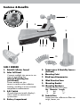
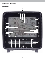
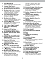
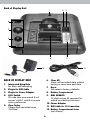
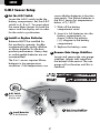
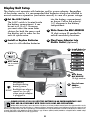
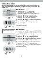
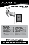
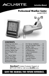
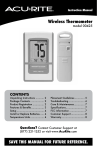
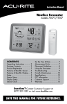
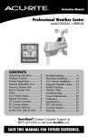
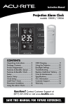
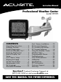
Instruction Manual
Professional Weather Center
model 01525
CONTENTS
Unpacking Instructions............ 2
Package Contents................... 2
Product Registration................ 2
Features & Benefits: 5-in-1........ 3
Features: Display Unit............. 4
Back of Display Unit................ 6
Setup..................................... 7
5-in-1 Sensor Setup................. 7
Display Unit Setup.................. 8
Set the Time & Date................ 9
Measurement Units................10
Set Language........................10
Placement Guidelines............. 11
5-in-1 Sensor Installation.........12
PC Connect Overview............13
PC Connect USB Modes.........13
PC Connect Software.............14
Using the Weather Center......15
Weather Ticker......................16
Programmable Alarms............18
Troubleshooting.................... 20
Care & Maintenance............. 23
Calibration........................... 23
Specifications........................ 25
FCC Information................... 25
Customer Support................. 26
Warranty............................. 26
Questions? Contact Customer Support at
(877) 221-1252 or visit www.AcuRite.com.
SAVE THIS MANUAL FOR FUTURE REFERENCE.
Congratulations on your new AcuRite product. To ensure the best
possible product performance, please read this manual in its entirety
and retain it for future reference.
Unpacking Instructions
Remove the protective film that is applied to the LCD screen prior to using this
product. Locate the tab and peel off to remove.
Package Contents
1. Display unit with tabletop stand
2. 5-in-1 sensor
3. Sensor mounting bracket
4. Mounting hardware
5. Snap-in debris filter for rain collector
6. Power adapter
7. USB cable
6. Instruction Manual
IMPORTANT
PRODUCT MUST BE REGISTERED
TO RECEIVE WARRANTY SERVICE
PRODUCT REGISTRATION
Register online
to receive 1 year
warranty protection
www.AcuRite.com
►Register a Product
2
Features & Benefits
7
1
2
9
11
3 4 5
8
6
10
5-IN-1 SENSOR
5. T emperature & Humidity Sensors
(internal)
1. R
ainfall Collector Funnel
2. Solar Cell Panel
6. Mounting Point
Converts sunlight into power to run
internal aspirating fan.
7. W
ind Speed Anemometer
Internal Aspirating Fan
(not shown)
8. Wind Direction Vane
Draws ambient air into sensor to reduce solar radiation heating, resulting in more accurate temperature measurement.
9. Mounting Bracket
10. Mounting Hardware
includes anchors & screws.
Qty Diameter Length
4
#4
1”
2
#6
½”
3. A-B-C Switch
ID code that must match display’s A-B-C switch to ensure units
synchronize.
11. Debris Filter
4. Battery Compartment
3
Snaps into rain collector to filter out twigs, leaves, etc.
Features & Benefits
Display Unit
41
3738 39 40
6
1
21
22
2
23
24
3
4
5
25
26
27
28
29
30
31
32
33
7
8
9
10
11
34
35
12
13
36
14 15
14
16
17 18
4
16
19 20
1.
2.
3.
4.
Peak Wind Speed
selected on display (#33). Press twice for all-time high and date recorded.
Highest speed from past 60 minutes.
Average Wind Speed
20.Activates Weather Ticker Message
21. Current Outdoor Temperature
Arrow icon indicates direction of all speeds from past 2 minutes.
Storm Alert Alarm On Indicator
Weather Select (top to bottom)
Heat index, dew point, wind chill, indoor temperature / humidity, rainfall rate (rain per hour)
22.Outdoor Temperature Alarm On Indicator
23.Current Outdoor Humidity
5. Current Barometric Pressure
Arrow icon indicates direction pressure is trending.
category data being displayed.
7. Learning Mode Icon
Disappears after weather forecast Self-Calibrating Forecasting pulls
data from the outdoor sensor to
generate your personal forecast.
28.All-Time Rainfall
29.Current Month Total Rainfall
30.Date
31.Clock
32.Display Unit Low Battery Indicator
33. Selectable Category
34. Record Highs
Activate alarm; press and hold to adjust alarm values.
Shown for current category selected on the display (#33).
35.Record Lows
15. Deactivates Weather Ticker Message
16."▲”/”▼” to Select Category (shown in #33) & Adjust Settings
17.“ “ Button
Shown for current category selected on the display (#33).
36. Weather Ticker™
37. Previous 2 Wind Directions
38.Current Wind Direction
39.Current Wind Speed
40.Wind Speed Alarm On Indicator
41. Touch Activated Backlight
Momentary during battery power, For setup preferences.
18. Weather Ticker Manual Cycle
Press to advance through messages.
19. All-Time Records Button
Press for all-time low and date Accumulates data during rainfall.
26.Rainfall Alarm On Indicator
27. 12 to 24 Hour Weather Forecast
self-calibration is complete.
8. 5-in-1 Sensor Signal Strength
9. 5-in-1 Sensor Low Battery Indicator
10. Alarm On/Off Indicator
for Selectable Category (#33).
11. Programmable Alarm Settings
12. Indicates Active Weather Ticker Message
During ticker customization mode.
13. Indicates Deactivated Weather Ticker Message
During ticker customization mode.
14. Alarm On/Off Button
Arrow icon indicates direction humidity is trending.
24. Outdoor Humidity Alarm On Indicator
25.Current Rainfall
6. Weather Select Button
Press to change the Weather Select temperature is trending.
recorded for current category 5
always on/off for power adapter
Back of Display Unit
1
2
3
4
5
6
7
8
9
10
BACK OF DISPLAY UNIT
11
6. Clear All
Clears all recorded data without
having to reset time and date
1. Integrated Hang Hole
for easy wall mounting
2. Plugin for USB Cable
7.Reset
Full reset to factory defaults
3. Plugin for Power Adapter
8. Battery Compartment
4.
9. MAC ADDRESS
12 digit unique ID required for online connectivity functions
A-B-C Switch
ID code that must match 5-in-1 sensor’s A-B-C switch to ensure units synchronize
10. Power Adapter
5. Clear Today
Clears data recorded since 12:00am
11. USB Cable for PC Connection
12. Battery Compartment Cover
(not shown)
6
SETUP
5-IN-1 Sensor Setup
1 Set the A-B-C Switch
Locate the A-B-C switch inside the
battery compartment. Set the A-B-C
switch to A, B or C. You must select
the same letter choices for both the
sensor and the display unit in order
for the units to synchronize.
2 Install or Replace Batteries
Batteries MUST be installed for
this product to operate. AcuRite
recommends high quality alkaline
or lithium batteries for the best
product performance. Heavy duty
or rechargeable batteries are not
recommended.
cause alkaline batteries to function
improperly. Use lithium batteries in
the 5-in-1 sensor for temperatures
below -4ºF / -20ºC.
1. Slide off the battery compartment cover.
2. Insert 4 x AA batteries into the
battery compartment, as
shown. Follow the polarity
(+/-) diagram in the battery
compartment.
3. Replace the battery cover.
3 Remove Rain Gauge Stabilizer
Locate and remove the rain gauge
stabilizer (plastic tab) taped into
the bottom of the sensor. The rain
gauge will not function until this is
removed.
The 5-in-1 sensor requires lithium
batteries in low temperature
conditions. Cold temperatures can
ABC
1
A-B-C Switch
Set to match
display unit
2
3
Install Batteries
4 AA Batteries
7
Rain Gauge Stabilizer
Remove and discard
Display Unit Setup
The display unit operates with batteries and/or power adapter. Regardless
of the power source, it is recommended that batteries always be installed to
ensure continuous operation (and retain records) in case of a power outage.
1 Set the A-B-C Switch
into the battery compartment,
as shown. Follow the polarity
(+/-) diagram in the battery
compartment.
The A-B-C switch is located inside
the battery compartment. It can
be set to A, B or C. However,
you must select the same letter
choices for both the sensor and
the display unit in order for the
units to synchronize.
3 Write Down the MAC ADDRESS
12 digit unique ID needed for
online connectivity functions.
2 Install or Replace Batteries
4 Plug Power Adapter into
Electric Outlet (optional)
Insert 6 x AA alkaline batteries
2
Install Batteries
6 AA Batteries
3
Write Down
MAC ADDRESS
12 digit number
4
Plug in Power
Adapter
(optional)
ABC
1
A-B-C Switch
set to match
sensor
Momentary
backlight during
battery power.
Backlight can always
LIGHT
remain on (or off)
when power adapter
is plugged in.
PLEASE DISPOSE OF OLD OR DEFECTIVE BATTERIES IN AN ENVIRONMENTALLY SAFE
WAY AND IN ACCORDANCE WITH YOUR LOCAL LAWS AND REGULATIONS.
BATTERY SAFETY: Clean the battery contacts and also those of the device prior to battery installation. Remove batteries from equipment which is not to be
used for an extended period of time. Follow the polarity (+/-) diagram in the battery compartment. Promptly remove dead batteries from the device. Dispose of used
batteries properly. Only batteries of the same or equivalent type as recommended are to be used. DO NOT incinerate used batteries. DO NOT dispose of batteries in fire,
as batteries may explode or leak. DO NOT mix old and new batteries or types of batteries (alkaline/standard). DO NOT use rechargeable batteries. DO NOT recharge
non-rechargeable batteries. DO NOT short-circuit the supply terminals.
8
Set the Time & Date
The clock and calendar are utilized to time stamp history records and other
data, so it is important to set the time and date soon after you power on the
display unit.
Set the Time
1. P
ress the "▲” or “▼” buttons until
“SET CLOCK?” is displayed on the
Selectable Category part of the display unit.
2. Press the “
” button to set the clock.
3. P
ress the “▲” or “▼” to adjust the hour.
Note the “AM” and “PM” indicators.
4. P
ress the “
” button to confirm hour selection.
5. Press the “▲” or “▼” to adjust minutes.
6. P
ress the “
selection.
” button to confirm minute
The clock is now set.
Note: The “ ” stays in
Selectable Categories,
even after setup.
Set the Date
1. P
ress the “▲” or “▼” buttons until “SET DATE?”
is displayed on the Selectable Category part of
the display unit.
2. Press the “
” button to set the date.
3. Press the “▲” or “▼” to adjust the month.
4. Press the “
” button to confirm month selection.
5. Press the “▲” or “▼” to adjust the day.
6. Press the “
” button to confirm day selection.
7. Press the “▲” or “▼” to adjust the year.
8. Press the “
” button to confirm year selection.
The date is now set.
9
Select Measurement Units
To select between standard units (mph, ºF, etc.) or
metric units (kph, ºC, etc.):
1. P
ress the “▲” or “▼” buttons until “SET UNITS?”
is displayed on the Selectable Category part of
the display unit.
2. Press the “
” button to set the unit preference.
3. P
ress the “▲” or “▼” to select “STAND” for
standard or “METRIC” for metric units.
4. Press the “
” button to confirm your selection.
5. N
ext, you will see “WIND MPH”. Press the
“▲” or “▼” to select MPH, KPH, or KNOTS
for wind speed units.
6. Press the “
” button to confirm your selection.
Units are now set.
Set Language
To select between English (default) or Spanish for the display unit language:
1. P
ress the “▲” or “▼” buttons until “SET LANG?” is displayed on the
Selectable Category part of the display unit.
2. Press the “
” button to set the language preference.
3. Press the “▲” or “▼” to select the desired language.
4. Press the “
” button to confirm your selection.
Language is now set.
Note: Display unit reverts to English language when display unit runs out of
power or is reset.
10
Placement for Maximum Accuracy
AcuRite sensors are sensitive to surrounding environmental conditions. Proper
placement of both the display unit and the sensor are critical to the accuracy
and performance of this product.
Display Unit Placement
Place the display unit in a dry area free of dirt and dust. To
ensure accurate temperature measurement, place out of direct
sunlight and away from heat sources or vents. Display unit stands
upright for tabletop use or is wall-mountable.
5-in-1 Sensor Placement
The 5-in-1 sensor is designed to remain outdoors all year long.
Choose an open location with no obstructions above or around
the sensor for the most accurate measurements.
Important Placement Guidelines
Display unit and sensor must be within 330 feet (100 m) of each other.
MAXIMIZE WIRELESS RANGE
lace units away from large metallic items, thick walls, metal surfaces, or other
P
objects that may limit wireless communication.
PREVENT WIRELESS INTERFERENCE
lace both units at least 3 feet (.9 m) away from electronic devices (TV,
P
computer, microwave, radio, etc.).
LOCATE AWAY FROM HEAT SOURCES
Position sensor away from heaters, air conditioners, chimneys, exhaust vents,
asphalt and concrete (surfaces that radiate heat).
LOCATE AWAY FROM HUMIDITY SOURCES
Avoid installing the sensor near pools, spas, or other bodies of water. Water
sources may impact humidity accuracy.
LOCATE AWAY FROM SPRINKLER HEADS
DO NOT install the sensor where it will be sprayed by a sprinkler system. This
may force water inside the sensor.
LOCATE AWAY FROM WIND & RAIN OBSTRUCTIONS
DO NOT mount the sensor with obstructions around it.
Consider a location that is a wide open area, with few
structures around to ensure accurate wind measurement.
Visit us online to view installation photos and
video, or learn more about AcuRite technology:
www.AcuRite.com/5in1
11
View Video
5-in-1 Sensor Installation Guidelines
INSTALLATION HEIGHT Mount the sensor at least 5 feet (1.5 meters) off the
ground (higher is better for wind measurement) in an open area. Secure to
fence post, 2”x 4” wood, 3/4” pole, etc. (not included)
LEVEL INSTALLATION Use the bubble level on the top of the sensor to ensure
level installation for accurate wind and rain measurement.
SOLAR CELL INSTALLATION Install the sensor with the solar cell facing SOUTH.
This ensures the cell receives as much sun as possible and orients wind
direction.
NO OBSTRUCTIONS
ABOVE
OR AROUND
5-in-1 Sensor Installation
1. F
asten mounting base
(included) to a post or pole
TH
(not included) using the 4
SOU
longer screws included in the
hardware bag.
2. Insert the mounting base into
the hole on the bottom of the
sensor.
3. M
ake sure the arrows on the
top of the sensor are pointed
in the proper direction and
the bubble level is centered.
The solar cell should be facing
south to properly orient the
wind direction.
(1.5 meters)
4. F
asten the sensor into the
mounting base using the 2
shorter screws included in the
hardware bag.
The 5-in-1 sensor is now
ready to use.
Clear Data Collected During Installation
When installation is complete, clear erroneous data from the display unit by
pressing the “CLEAR TODAY” button, on the back of the display inside the
battery compartment. This button will clear data recorded since 12:00 am.
Basic Setup is Complete
The 5-in-1 sensor will now synchronize with the display unit. It may take a few
minutes for synchronization to complete. If both or one of the units appear to
be functioning improperly, please refer to the troubleshooting section.
12
PC Connect Overview
PC Connect lets you access your Weather Center data in the following ways:
• Data File: Display unit logs (or stores) data so that you can download it to a PC in a data file (CSV or comma-separated values file).
• PC Weather Widget: View data on your PC’s screen as a widget.
• Web Browser or Smartphone: Monitor sensor data remotely using AcuRite’s
free AcuRite online software, or from a mobile device using the free AcuRite
app, available from the iPhone App Store or Android Market.
DISPLAY UNIT...
PC Connect USB Modes
To setup PC Connect, you must first select
a USB mode on the display unit:
USB Shows Stores Streams
Mode Data Data Online*
USB Mode 1: Display Logging ON
•Display unit logs (stores) up to 2 weeks of
data in memory. When memory nears
capacity, display unit’s Weather Ticker
displays an alert to download memory soon.
•Transfer data to your PC using PC Connect.
1
2
3
4
USB Mode 2: Display Logging OFF (DEFAULT)
•Display unit DOES NOT log (save) any data in memory for PC transfer.
USB Mode 3: Display Logging ON/Internet Bridge Mode
•Display unit logs (stores) up to 2 weeks of data in memory.
•Transfer data to your PC using PC Connect.
•Stream your data from your weather center to online sources.*
USB Mode 4: Display Logging OFF/Internet Bridge Mode
•Display unit DOES NOT log (save) any data in memory.
•Stream your data from your weather center to online sources.*
* PC and internet connection must remain ON to continuously stream data from your weather center to online sources or the AcuRite mobile app.
Set the PC Connect USB Mode
1. P
ress the “▲” or “▼” buttons until “SET USB
MODE?” is displayed on the Selectable Category
part of the display unit.
2. Press the “
” button to set the mode preference.
3. Press the “▲” or “▼” to select the USB mode.
4. Press the “
” button to confirm your selection.
PC Connect USB Mode is now set.
13
Download the PC Connect Software
PC Connect software is available as a free download online. The PC Connect
instruction manual is a PDF file that is included in the software download.
Read the manual to learn how to setup PC Connect preferences and advanced
features.
1
SUPPORT
Visit www.AcuRite.com and click
on PC Connect Download under
the SUPPORT menu to download
the software to your computer.
small end of USB cable
2 Connect
into USB plugin, on the back
of the display unit inside the
battery compartment area.
(PC)
large end of the USB
3 Connect
cable to a USB port on your PC.
Click on the “setupacu-link” file
4 and
follow the instructions to install
Acu-Link PC Connect
Acu-Link PC Connect
PC Connect software. A folder named
“AcuRite” will be installed on your PC.
NOTE: PC Connect software may take
up to 1 minute upon startup to receive
data from display unit.
Acu-Link PC Connect v. X on your computer
PC Connect
PC Connect is now ready for use.
14
OPERATION
Using the Professional Weather Center
Learning Mode
Self-Calibrating Forecasting use a unique algorithm to analyze changes in
pressure over a time period (called Learning Mode) to determine your altitude.
After 14 days, the Learning Mode icon disappears from the display screen. At
this point, the self-calibrated pressure is tuned in to your location and the unit is
ready for superior weather prediction.
Weather Forecast
AcuRite’s patented Self-Calibrating Forecasting provides your personal forecast
of weather conditions for the next 12 to 24 hours by collecting data from
the sensor in your backyard. It generates a forecast with pinpoint accuracy personalized for your exact location.
STORM
LIKELY
PARTLY
CLOUDY
RAIN
LIKELY
CLOUDY
SNOW
LIKELY
CHANCE OF MIXED
RAIN & SNOW
View the complete list of icons at www.AcuRite.com/acurite-icons
Weather Select
= Heat Index
Features weather data groups
shown at right. To change
“Weather Select” category,
press the selection arrow
button just to the left of the
weather select display area.
= Dew Point
= Wind Chill
= Indoor Conditions
= Rainfall Rate (in./hour)
Rainfall Event
The rainfall feature tracks rain accumulation over all-time, the current month,
and current rainfall event. Current event clears when no rain registers for 8
hours OR no rain registers for 1 hour and pressure rises by .03inhg or more.
Barometric Pressure
Subtle variations in barometric pressure greatly affect the weather. This
weather center displays the current pressure with an arrow icon to indicate the
direction the pressure is trending (FALLING, STEADY, or RISING).
15
Weather Ticker ™
The Weather Ticker automatically streams your real-time weather information
and alerts as scrolling text in the lower part of the display unit screen.
You can manually cycle through all the available messages by pressing “
Default WEATHER TICKER messages are pre-loaded as follows:
FORECAST
12 to 24 hour future weather forecast
MOON PHASE
Current moon phase
INDOOR COMFORT
Dry, OK or humid comfort level
IT FEELS LIKE __
OUTSIDE
Calculates what temperature it feels like outdoors
(based on temperature, humidity and wind speed)
OUTDOOR TEMP THIS
WEEK HIGH
Highest temperature recorded this calendar week
OUTDOOR TEMP THIS
WEEK LOW
Lowest temperature recorded this calendar week
OUTDOOR TEMP THIS
MONTH HIGH
Highest temperature recorded this calendar month
OUTDOOR TEMP THIS
MONTH LOW
Lowest temperature recorded this calendar month
Additional Messages Include:
NEW HIGH TEMPERATURE RECORD
NO RAIN RECORDED SINCE ____
NEW LOW TEMPERATURE RECORD
WEATHER ALARM MESSAGES
NEW WIND SPEED RECORD TODAY
SENSOR BATTERIES LOW
CURRENT RAINFALL RATE
SENSOR SIGNAL LOST
CURRENT RAIN EVENT STARTED
Adjust the Weather Ticker Speed
1. Press the “▲” or “▼” buttons until “TICKER SPEED” is displayed on the
Selectable Category part of the display unit.
2. Press the “
” button to set the speed preference.
3. Press the “▲” or “▼” to select a speed: SLOW, NORMAL, or FAST.
4. Press the “
” button to confirm your selection.
Weather Ticker speed is now set.
16
”.
Customize Weather Ticker Messages
Customize which messages you want to scroll across the WEATHER TICKER:
1. Press the “
” button to manually cycle through each message available.
2. During the MANUAL REVIEW:PRESS the “
” button to activate the
current scrolling message. The corresponding “
” appears on screen
to the left of the message to indicate the message is now active in the ticker
cycle.PRESS the “ ” button to deactivate the current scrolling message.
The corresponding “ ” appears on screen to the left of the message to
indicate the message is now deactivated from the ticker cycle.
Please note: Messages can only be added and removed to the ticker cycle
during manual review. The “
” and “ ” buttons do not add or remove
messages during the automatic cycle.
Message
activated
Message
deactivated
Remove
message
from cycle
Manual cycle
through
messages
17
Add
message
to cycle
Programmable Weather Alarms
Each Selectable Weather Category features an alarm option. When an alarm
sounds, the display unit emits audible beeping and flashes the affected category,
its alarm settings, and any other relevant data.
Some alarms can be customized to alert you when your programmed value is
reached. Alarms include:
OUTDOOR HUMIDITY
LOW
HIGH
OUTDOOR TEMP
LOW
HIGH
STORM ALARM
HIGH
INDOOR HUMIDITY
LOW
HIGH
INDOOR TEMP
LOW
HIGH
WIND CHILL
LOW
DEW POINT
LOW
HEAT INDEX
HIGH
RAIN
HIGH
WIND SPEED
HIGH
HIGH
The rain alarm does not require a preset numerical value, but instead sounds
as soon as rain is recorded. Similarly, the storm alarm sounds when a large
atmospheric pressure drop occurs, which usually indicates an oncoming storm.
Note: The storm alarm is NOT intended to be a safety device or warning system.
Set a Weather Alarm
1. Choose the weather category for which you wish to set an alarm by
pressing the “▲” or “▼” buttons until the category is displayed on the
Selectable Category part of the display unit.
2. To program a value (only applies to alarms that require a value), press
AND HOLD the “
” button underneath the alarm you wish to set until the
“ ” indicator appears and the alarm setting flashes.
3. Adjust the alarm value by pressing the “▲” or “▼” buttons.
4. Press the “
” button to confirm a value.
5. Next, press the “
” button to activate the alarm (the X indicator
disappears when alarm is activated).
Alarm is now programmed and turned on.
18
ICON DEFINITIONS
= Alarm On
= Alarm Off
= Adjust Mode
= Low Value
= High Value
BUTTON FUNCTIONS
Silence a Sounding Alarm
The alarm sounds initially for a few minutes,
then silences itself. The alarm then sounds every
few minutes afterwards until one of the
following happens:
1. “SNOOZE” - Press any button. Alarm
silences, but sounds again if the alarm
condition reoccurs.
2. Turn alarm “OFF” - Deactivates alarm.
19
Press to activate or
deactivate an alarm.
Press and hold to set
or adjust an alarm
value.
Troubleshooting
Problem
No outdoor sensor
reception
no bars
Possible Solution
•R
elocate the display unit and/or the 5-in-1 sensor.
The units must be within 330 ft (100 m) of each other.
•M
ake sure both units are placed at least 3 feet
(.9 m) away from electronics that may interfere with
the wireless communication (such as TVs, microwaves,
computers, etc).
•U
se standard alkaline batteries (or lithium batteries in
sensor when temperature is below -4ºF/-20ºC). Do not
use heavy duty or rechargeable batteries. NOTE: It
may take up to 20 minutes for display unit and sensor
to synchronize after batteries are replaced.
•S
ynchronize the units:
1. B
ring both the sensor and display unit indoors and
remove batteries from each.
2. Reinstall batteries in outdoor sensor.
3. Reinstall batteries in display unit.
4. L et the units sit within a couple feet of each other
for about 20 minutes to gain a strong connection.
Outdoor
t emperature
is flashing or
showing dashes
Flashing of the outdoor temperature may be an
indication of wireless interference.
•M
ake sure the A-B-C switch in the battery
compartments of both the display unit and sensor are
switched to the same letter. You may choose A, B or
C; but both units must match to sync up. Sometimes
changing to a different channel can help.
Weather Ticker
Hard to Read
• Slow down the speed of the ticker (see page 16).
Inaccurate forecast
•W
eather Forecast icon predicts conditions for the next
12 to 24 hours, not current conditions.
•H
as Learning Mode icon disappeared from the
display unit? Learning Mode must complete before
forecast and pressure will be accurate.
•A
llow unit to run continuously for 33 days. Battery
removal or resetting the display unit will restart
Learning Mode. After 14 days, forecast should be
fairly accurate, however Learning Mode calibrates for
a total of 33 days.
20
Troubleshooting
Problem
Possible Solution
Inaccurate
temperature or
humidity
•M
ake sure both the display unit and 5-in-1 sensor
are placed away from any heat sources or vents (see
page 11).
•M
ake sure both units are positioned away from
moisture sources (see page 11).
•M
ake sure 5-in-1 sensor is mounted at least 5 ft off of
the ground.
• Calibrate indoor and outdoor temperature and
humidity (see page 23).
No rainfall
• Check to ensure the rain gauge stabilizer (plastic tab)
has been removed from the bottom of the sensor (see
page 7).
• Clear debris, such as leaves, out of the rain collector
funnel and debris screen.
• Calibrate the Rain Gauge (see page 24).
Inaccurate wind
readings
•W
hat is wind reading being compared to? Pro
weather stations are typically mounted at 30 ft high
or more. Make sure to compare data using a sensor
positioned at the same mounting height.
•C
heck location of the sensor. Ensure it’s mounted a
minimum of 5 ft in the air with no obstructions around
it (within several feet).
•Ensure wind cups are spinning freely. If they hesitate
or stop try lubricating with graphite powder or spray
lubricant.
USB connectivity
not working
•C
heck that the batteries are installed correctly.
Batteries may need to be replaced.
•R
eset the display by pressing the reset button, located
on the back of the display unit. Date and time will
need to be entered after a reset.
Display screen
not working
•C
heck that the batteries are installed correctly.
Batteries may need to be replaced.
•R
eset the display by pressing the reset button, located
on the back of the display unit. Date and time will
need to be entered after a reset.
21
Troubleshooting
Problem
Possible Solution
Cannot access data
online or on the
AcuRite mobile app
• Confirm the status readout in PC Connect software on
your PC indicates that data was uploaded OK.
• Make certain you created an account or logged into
your existing account on www.acu-link.com, and that
you have setup your display unit MAC ADDRESS
online, as well.
• Check that the USB cable is securely connected to the
display unit AND to your PC USB port.
• Make certain the display unit is powered on.
• Make certain the PC your display unit is connected to
is always powered on.
• Make certain the PC your display unit is connected to
is always connected to the internet.
• Confirm the display unit USB mode is 3 or 4.
• Confirm your display unit MAC ADDRESS is entered
into the “UPLOAD” window correctly in the PC
Connect Software on your PC.
• Confirm that the “ENABLE” box is checked in the
“UPLOAD” window in the PC Connect Software on
your PC.
• Confirm your display unit’s MAC ADDRESS is correct
in your account at www.acu-link.com and on the
AcuRite mobile app.
• Restart the PC Connect Software.
• Restart your PC.
PC Connect software
data is different than
display unit data
• Check that the USB cable is securely connected to the
display unit AND to your PC USB port.
• Confirm that the correct USB mode is selected on your
display unit.
• Restart the PC Connect Software.
• Unplug the USB cable from your PC for about 1
minute, re-insert.
• USB port may be malfunctioning, try another USB
port.
If your AcuRite product does not operate properly after trying
the troubleshooting steps, visit www.AcuRite.com or call
(877) 221-1252 for assistance.
22
Care & Maintenance
Display Unit Care
Clean with a soft, damp cloth. Do not use caustic cleaners or abrasives. Keep away
from dust, dirt and moisture. Clean ventilation ports regularly with a gentle puff of air.
5-in-1 Sensor Care
Clean the Sensor
Clean with a soft damp cloth. Do not use caustic cleaners or abrasives that will mar the
polished surfaces of the rain collection funnel or the solar cell. Scratches will result in
decreased performance and reliability.
Insect Prevention
Insects may cause obstructions and interrupt data by nesting in or on the 5-in-1 sensor.
To limit this problem, spray sensor with a household insect repellent. Consult the insect
repellent instructions prior to use.
Snow & Freezing Weather
The 5-in-1 sensor will not be damaged by freezing conditions. NOTE: If the rain collector cup fills with snow and then melts, it will register as rain on the display unit.
Clean the Rain Collector Cup
Remove and empty rain collector debris filter. The debris filter is located in the rain collector funnel. Remove from the top by gently squeezing and pulling out.
Clean the Wind Vane & Anemometer
Remove foreign matter from the outside of the sensor for free movement of the wind
vane and anemometer. If needed, use a small amount of spray lubricant, clear silicone
or graphite powder on the anemometer for improved movement.
Calibration
Calibrate Temperature & Humidity
The indoor / outdoor temperature and humidity readings can be calibrated on the
display unit to improve accuracy. Calibration improves accuracy when 5-in-1 sensor
placement or environmental factors impact your data accuracy.
1. Choose the weather category you wish to calibrate by pressing the “▲” or “▼”
buttons until the category is displayed on the Selectable Category part of the
display unit.
2. P
ress AND HOLD the “▲” or “▼” buttons and the “
for 15-20 seconds. ” button all at the same time
• The display unit beeps, and all display data is hidden except for the value being
calibrated.
•“
” (calibrate) and arrows appear next to the value being calibrated.
23
3. Press the “▲” or “▼” buttons to calibrate the data value higher or lower from the
actual reading.
4. Press the “
Note: The “
values.
” button to confirm the calibration a
djustment.
” icon remains illuminated next to calibrated
Calibrate the Rain Gauge
The rain gauge on the 5-in-1 sensor can be calibrated to improve accuracy.
Items Needed: 5-in-1 sensor, display unit, plastic cup, pin, screw driver
1. First, ensure 5-in-1 sensor is perfectly level using built-in bubble level.
2. Place display unit close so you can monitor it during calibration.
3. Make a pin hole in the bottom of a plastic cup. Hold the cup over the rain gauge
and fill it with exactly 1 cup (8oz) of water, allowing the water to drip into the rain
gauge. You should hear the internal buckets tip and see water drain through the rain
gauge.
4. A few seconds after each bucket tip, the display unit displays rainfall in
approximately 0.01” or more increments.
5. The cup of water should take more than 20 minutes to empty; a quicker period will
result in inaccurate calibration. Try to simulate a normal steady rainfall. When cup is
empty of water, display unit should register 1.06”
Tips
• There should be nearly an equal number of water drops (about 25 water drops)
between bucket tips. If not, adjust the calibration screws on the bottom of the 5-in-1
sensor until an equal number of water drops are tipping the buckets. Then, restart the
calibration procedure.
• If you don’t hear the buckets tipping and see water dripping alternately out of
each drain, there may be an issue with the rain gauge or it’s adjustment. See
Troubleshooting on page 21.
Adjustment
If the rain gauge doesn’t register close to 1.06”, make an EQUAL adjustment to the two
calibration screws on the bottom of the 5-in-1 sensor. Turning screws clockwise increases
rainfall; counter clockwise decreases rainfall.
• To adjust the rainfall reading by 2% turn both screws 1/8 of a turn.
• To adjust the rainfall reading by 4% turn both screws 1/4 of a turn.
• To adjust the rainfall reading by 8% turn both screws 1/2 of a turn.
Watch the video at www.acurite.com/5n1
24
Specifications
TEMPERATURE RANGE
Outdoor: -40ºF to 158ºF; -40ºC to 70ºC
Indoor: 32ºF to 122ºF; 0ºC to 50ºC
HUMIDITY RANGE
Outdoor: 1% to 99%
Indoor: 16% to 98%
WIND SPEED
0 to 99 mph; 0 to 159 kph
WIND DIRECTION
INDICATORS
16 points
RAINFALL
0 to 99.99 in; 0 to 99.99cm
WIRELESS RANGE
330ft / 100m depending on home construction materials
OPERATING FREQUENCY
433 MHz
POWER
Display: 4.5V AC adapter
6 x AA alkaline batteries (optional)
Sensor: 4 x AA alkaline or lithium batteries
DATA REPORTING
Wind Speed: 18 second updates; Direction: 30 seconds
Outdoor temperature & humidity: 36 second updates
Indoor temperature & humidity: 60 second updates
PC Connect CSV Data Logging: 12 minute intervals
PC Connect to AcuRite Software/App: 18 seconds
DISPLAY UNIT MEMORY
512 kilobytes (not expandable)
PC CONNECT SYSTEM
REQUIREMENTS
Windows® XP / Vista / 7 and available USB port.
High speed internet is required to use some advanced
features of PC Connect, such as the AcuRite software
and app.
FCC Information
This device complies with part 15 of FCC rules. Operation is subject to the following two conditions:
1- This device may NOT cause harmful interference, and
2- This device must accept any interference received, including interference that may cause undesired operation.
This equipment has been tested and found to comply with the limits for a Class B digital device, pursuant to Part 15 of the FCC rules. These limits are designed
to provide reasonable protection against harmful interference in a residential installation. This equipment generates, uses and can radiate radio frequency
energy and, if not installed and used in accordance with the instructions, may cause harmful interference to radio communications. However, there is no
guarantee that interference will not occur in a particular installation. If this equipment does cause harmful interference to radio or television reception, which
can be determined by turning the equipment off and on, the user is encouraged to try to correct the interference by one or more of the following measures:
• Reorient or relocate the receiving antenna.
• Increase the separation between the equipment and the receiver.
• Connect the equipment into an outlet on a circuit different from that to which the receiver is connected.
• Consult the dealer or an experienced radio/TV technician for help.
NOTE: The manufacturer is not responsible for any radio or TV interference caused by unauthorized modifications to this equipment. Such modifications could
void the user authority to operate the equipment.
This device complies with Industry Canada licence-exempt RSS standard(s).
Operation is subject to the following two conditions:
(1) This device may not cause interference, and
(2) This device must accept any interference received, including interference that may cause undesired operation of the device.
25
Customer Support
AcuRite customer support is committed to providing you with best-inclass service. For assistance, please have the model number of this
product available and contact us in any of the following ways:
(877) 221-1252
[email protected]
24/7 support at www.AcuRite.com
► Installation
Videos
► Register
your Product
► Instruction
Manuals
► Support
User Forum
► Replacement
Parts
► Submit
IMPORTANT
Feedback & Ideas
PRODUCT MUST BE REGISTERED
TO RECEIVE WARRANTY SERVICE
PRODUCT REGISTRATION
Register online
to receive 1 year
warranty protection
www.AcuRite.com
►Register a Product
Limited One Year Warranty
At AcuRite, we proudly uphold our commitment
to quality technology. Chaney Instrument Co.
warrants that all products it manufactures to
be of good material and workmanship, and to
be free of defects when properly installed and
operated for a period of one year from the
date of purchase.
not be breached, and Chaney will give no credit for products
it manufactures which have received normal wear and tear,
been damaged (including by acts of nature), tampered, abused,
improperly installed, damaged in shipping, or repaired or altered
by others than authorized representatives of Chaney.
The above-described warranty is expressly in lieu of all other
warranties, express or implied, and all other warranties are
hereby expressly disclaimed, including without limitation the
implied warranty of merchantability and the implied warranty
of fitness for a particular purpose. Chaney expressly disclaims
all liability for special, consequential or incidental damages,
whether arising in tort or by contract from any breach of this
warranty. Some states do not allow the exclusion or limitation
of incidental or consequential damages, so the above limitation
or exclusion may not apply to you. Chaney further disclaims all
liability from personal injury relating to its products to the extent
permitted by law. By acceptance of any of Chaney’s products,
the purchaser assumes all liability for the consequences arising
from their use or misuse. No person, firm or corporation is
authorized to assume for Chaney any other liability in connection
with the sale of its products. Furthermore, no person, firm or
corporation is authorized to modify or waive the terms of this
paragraph, and the preceding paragraph, unless done in writing
and signed by a duly authorized agent of Chaney. This warranty
gives you specific legal rights, and you may also have other rights
which vary from state to state.
We recommend that you visit us at
www.AcuRite.com for the fastest way to
register your product. However, product
registration does not eliminate the need to
retain your original proof of purchase in order
to obtain warranty benefits.
Chaney Instrument Co. warrants that all products it
manufactures to be of good material and workmanship, and to be
free of defects when properly installed and operated for a period
of one year from the date of purchase. Remedy for breach of
this warranty is limited to repair or replacement of the defective
item(s). Any product which, under normal use and service, is
proven to breach the warranty contained herein within ONE YEAR
from date of sale will, upon examination by Chaney, and at its
sole option, be repaired or replaced by Chaney. Transportation
costs and charges for returned goods shall be paid for by
the purchaser. Chaney hereby disclaims all responsibility for
such transportation costs and charges. This warranty will
For in-warranty claims:
Chaney Instrument Co. | 965 Wells St. | Lake Geneva, WI 53147
26
27
Weather
Stations
Temperature
& Humidity
Weather
Alert Radio
Kitchen
Thermometers
& Timers
Clocks
It’s More than Accurate, it’s
AcuRite offers an extensive assortment of precision instruments,
designed to provide you with information you can depend on to
Plan your day with confidence™.
www.AcuRite.com
Printed in China
01525 INST 041714
©Chaney Instrument Co. All rights reserved. AcuRite is a registered trademark of
the Chaney Instrument Co., Lake Geneva, WI 53147. All other trademarks and copyrights are the property of their respective owners. AcuRite uses patented technology.
Visit www.AcuRite.com/patents for details.