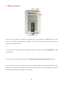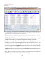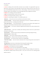
1
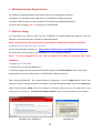
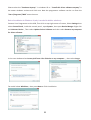
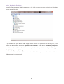
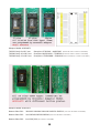
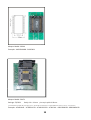
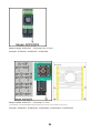
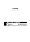
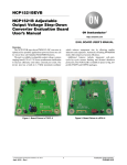
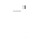
TNM Programmer 5000 / 2000+
For Windows 8 / 7 / Vista / XP
User Manual
TNM Electronics Ltd.
www.TnmElectronics.com\English\5000.html
www.TnmElectronics.com\English\programmer.htm
1
Contents
1. System Requirements.
2. Software Setup.
-
Installation from the TNM Website.
Installation from CD-ROM.
Windows 8-64 bit installation
Driver Installation Problems.
3. Utility Software Installation.
- TNM Nand Programmer Installation.
- Serial Port Emulator Installation.
4. Hardware Review.
5. Software Review.
- Main Screen.
- Menu & Toolbar.
- Software Shortcuts
6. IC Insertion in ZIF.
7. Copying a chip.
8. Gang Programming.
9. Adaptors
2
1. Minimum System Requirements:
• A desktop or laptop computer with Intel Pentium or an equivalent processor.
• Windows XP / Windows Vista / Windows 7 or Windows 8 operating system.
• At least 1 GB free space on your hard drive, for Nand Chips,1GB+Nand Capacity
• At least one standard (USB 2.0) connector for Model 5000.
2. Software Setup
You can install your software either from the CD-ROM or by downloading the program from our
website. Instructions for both methods are described below.
NOTE: Do Not Connect The Programmer to The Computer USB before Software Installation!
Installation from TNM Electronics Website
You can download the software at : http://www.tnmelectronics.com/English/Downloads.htm.
Once you have saved the file to your computer, run it to setup the software.
NOTE: For future Upgrades you can click on Upgrade link inside the software from menu
help/About.
Installation from CD-ROM
1. Insert the CD into the CD-ROM drive.
2. Autorun program will be started automatically, Select the “Install Product” item. If the setup
program does not start automatically, run SETUP.EXE located in the CD.
After Running SETUP.EXE , The system displays a dialog box , Press the Next button ,then in the
next box, you can change the default installation path (Not Recommended), Then press Next Again
and at the end, Press Finish. After the software installation, please connect the USB cable to the
programmer and your PC. “Found New Hardware Wizard” box will be opened like picture below.
Windows Vista, Windows 7
Windows XP
3
Please select the “Continue Anyway“ in windows XP or “Install this driver software anyway” in
the newer windows versions and click next. Now the programmer software can be run from the
“Start /Programs /TNM” menu shortcut.
Driver Installation in Windows 8 (only is needed in 64-bits windows):
Connect Your Programmer to the USB, Then click on top-right corner of screen, Select Settings then
select Control Panel , Inside the control panel , open System , then open Device Manger. Right click
on Unknown Device , Then select Update Driver Software and then select Browse my computer
for driver software.
In the next window select Let me pick from a list of device on my computer… , then select Jungo
For model select WinDriver , then press Next to finish installation.
4
Driver Installation Problems:
Normally after connecting TNM programmer to the USB, you must see your device in the Windows
Device manger like this:
If you couldn’t see your device under Jungo tree or if there is a yellow or red warning sign, right
click on the device name and select “Update Driver Software” . Then select “Browse My Computer
for driver software” then find the correct path for driver, which usually is “C:\Program
Files\TNM\Programmer\Wdreg” .
You Can Also delete the driver & then select reinstall the Driver option form Start Menu while the
USB connector is disconnected.
5
3. Utility Software Installation ( Only in Model 5000 ):
Here is the list of default companion utility software. Check our website for future software.
TNM Nand Programmer: Nand flash memories (memories for flash disks, MP3 Players & Digital
cameras ) can only be programmed by this software. Install this program from installation menu or
from “CD-Drive:\Nand Programmer\Setup.exe” . After the installation you can read instruction
manual by pressing the Help button.
Serial Port Emulator: Please copy the contents of the “Serial Port Emulator” folder in the CD-ROM
to your favorite location in your hard disk, then run Serial.exe . Your TNM-5000 programmer will
emulate a serial port, then you must install the serial port driver from “Serial_DRIVER” folder.
Then by connecting the ISP cable of programmer directly to RX/TX pins of microcontrollers , you can
program them by many free ISP softwares like Atmel Flip or ST-Flasher.
You will find more information in Serial.exe software helps.
Note: Before Using the Utility Programs, you must install TNM Programmer Software first. (part2)
6
4. Hardware Review:
Red LED Indicator: When you connect the programmer to the USB port, this LED blinks once and
then turns off. After executing the PC program, this LED turns on (Power-On) and during data
transfer the LED blinks (Busy).
ZIF Socket: Pin 1 of all devices must be aligned to the pin 1 of the ZIF socket. Model-5000 has a 48
pin ZIF Socket.
ISP Connector: See connector map from the “Help\User Manual\ISP Connector Pinout” Menu.
Power Connector (only in Model-5000 ): This is an auxiliary power connector and normally it’s not
necessary. If in the software you got a warning message because of low USB voltage, Connect the
9v power supply. Polarity of supply is not important.
7
. Software Review:
Main Screen
The main screen is illustrated below. Each part is labeled with a number and described below.
1. The Main Menu provides access to the File, Buffer, Device, Digital Tester and Help menus.
Refer to the Menu & Toolbar section or more information.
2. The Toolbar includes icons for quick access to common functions. Refer to the Menu & Toolbar
section or more information.
3. The Hex-Editor Window, Including the Address, Hex Values and ASCII Values. The buffer
contents are showed in here. You can double-click in there for editing the stored values.
4. The Information area, Shows you the Selected device name, Programming algorithm, the
selected device chip size (total programmable memory of the selected device in bytes) , The
selected device Manufacturer and Pin numbers, Vcc is the voltage for the device supply, Vpp is
the device programming voltage. Buffer size is the size (in bytes ) of the loaded or readed data
into the buffer. Checksum is the 16-bit checksum of the loaded or the readed data into the buffer.
OK/Fail is the number of successful or failed actions. File Name is the last loaded file name into
the buffer.
5. Check Log icon to switch to log window. A history of user actions will be shown instead of
Hex-Editor. Also last action always is displayed at bottom of screen.
8
Menu & Toolbar:
1. File Menu
a. Load: For loading a file to the buffer and show it by hex editor. The supported file types are:
binary (bin), Intel Hex (hex), Xilinx Cpld jedec file (jed), Xilinx FPGA bit file (bit), Serial Vector File
(svf) , Atmel EEPROM file (eep) & Altera Jam file . After loading a SVF file all the actions except the
SVF player button will be disabled. You can also Drag & Drop files to programmer window.
b. Reload: For reloading a previously loaded file.
c. Save: For saving the buffer contents to the current file.
d. SaveAs: For saving the buffer contents to a file.
e. Setup: For customizing the software. The available options are:
- Notify me ... : Select this item for the notification at the end of an action.
- Warning message ... : During the device programming If this item is checked and buffer size is
greater than device size , a message box will warn you.
- Auto Detect Device ... : If the selected device is not identical to the device under program, the
programmer automatically will identify the device. (If the device has an ID).
- Continue When ... : If this item is checked, Programming will be done even when the Device ID is
not present.
- Show device info ... : If this item is checked, after selecting a device from the list, specific device
information will be shown.
- Ask me before ... : Check this item to prevent accidental file overwriting during file saving.
- Disable Sounds: For silence mode.
- Disable Alt … : Turns off ALT hotkey running in other programs.
- Ask before Erase … : Always ask your permission to erase a device.
- Pin Connection … : Pin continuity tester on/off (only in Model5000).
- Chip Power Supply … : You can increase or decrease VCC of chips during read or write about %5
more or less.
- ISP Delay Time: Use this item to slow down ISP clock speed for low MCU clocks.
- Clock out: Selecting the frequency of clock on ISP pin 4 of Model 5000.
f. Language: List of available user interface languages.
g. Recent Files: list of the last recent opened files for fast loading.
h. Save/Load All Setting: For saving & restoring all software settings including the selected chip ,
the loaded file, software setup and all chip fuses . Every user can save his or her working project
and then restore it.
9
g. Exit: To exit the programmer software.
2. Buffer Menu
a. Edit Enable: For enabling the hex editor edit mode. Also you can double click on the hex-editor
window to enable it.
b. Fill: For Filling the buffer from the start to the end address with a value.
c. Swap Bytes: For swapping two consequent bytes to convert from Little Endian format to Big
Endian.
d. Search: For finding a text or hex string in the buffer.
e. Copy: For copying a part of buffer to another place in the buffer.
f. Properties: Only available for specific devices to program and verify a part of a device.
g. Jump: Jumping to an address in the buffer.
h. Auto Serial Number: You can specify a part of the buffer with arbitrary size and an increment
factor, the initial value of this buffer point will be increased every time you press AUTO key.
i. Load Encryption Table: For 87C51 MCU. You can load 64 byte binary encryption table to memory
(it won’t be shown in the hex editor) and then load it to the device.
j. Reset OK/Fail Counter: Resets the OK/Fail counter value to zero.
3. Device Menu:
a. Erase: For erasing the device memory contents.
b. Blank Check: For Checking the device is blank or not.
c: Program: For transferring buffer to the device memory. If the buffer size is greater than the
device memory, only the first part of the buffer with a size equal to the device memory will be
transferred. Programming will be done with verification. For programming the MCU devices with
internal EEPROM, Size of the buffer must be equal to sum of the FLASH memory and EEPROM.
d. Read: For reading back the device contents to the program buffer and the hex editor window.
e. Lock bits and Fuses Programming: For transferring the lock bits and fuse bits value to the device.
f. Fuse & Lock Configuration: For setting fuse bit values. After setting these values you can transfer
them to the device (refer to part 3.e)
g. Read MCU EEPROM: In microcontrollers with internal EEPROM you can read EEPROM contents
to the start of the buffer.
Note: This is different With Read (3.e) option. By Read button all the flash and EEPROM will be
readed and be copied to the buffer in order and EEPROM data are placed after flash data.
10
h. Write MCU EEPROM: Like part 3.g.
i. Verify MCU EEPROM: Like part 3.g.
j. Auto: Automatic sequence of actions. Use “Edit Auto” to edit the sequence.
k. Edit Auto: You can check sequence of actions for a device. For mass device programming, check
“detect Insertion & repeat” item and after the end of Auto sequence just replace the device. The
programmer automatically will sense the device insertion and repeat the auto sequence.
l. Select: For selecting a device from a list.
m. Recent Selected Devices: List of the four recent selected devices for fast device selection.
4. Digital Tester Menu
a. TestIC: For testing a TTL/CMOS device from a list. You can add a vector test to the list file in
LIB\TESTLIB.TXT.
b. Detect IC: For matching the result of an unknown device vector test with the list file. The
programmer can only find devices within the list.
5. Help Menu
a. Programmer SelfTest: You can check programmer internal circuit by this option.
b. Selected Device Info: If there is any info available about the selected device, an information box
will be opened.
c. About: You can get some info about the product and there is an Upgrade Link in this window.
6. Detect Button
The programmer search it’s database for all detectable chips and show you a list of matched
devices. Your device must have and internal manufacturer ID to be detectable. i.e Serial EEproms &
Eproms haven’t IDs and are not detectable.
11
Software Shortcuts:
Keyboard Shortcuts:
ALT+A: Auto Sequence Programming
ALT+E: Erase
ALT+B: Blank Check
ALT+R: Read
ALT+P: Program
ALT+S: Select
ALT+F: Fuse bit Programming
ALT+L: Load a file
ALT+Z: Save a file (Save As)
F3: After first search in buffer , for next item finding.
Mouse Shortcuts:
Drag a file from any folder & drop on Hex Editor window to load a file
Double Click on Hex editor window to enable editing.
Right Click on Hex editor window to open Buffer Submenu.
Right Click on Log window to open Log Submenu.
Right Click on Select button in main screen to show selected device information box.
Right Click on Auto button in main screen to show Edit Auto window.
Double Click on OK/Fail text in main screen to reset OK/Fail counter.
12
6. IC Insertion in ZIF:
Pin1 of the all Chips must be inserted in the topmost place of the programmer ZIF socket. Only
there is a few exceptions, which you will be informed by software.
Pin 1 of the chips is specified with a round hole or a Wedge.
You must place SMD chips in adaptors according to the mentioned rule too.
13
7. Copying a Chip:
To copy a chip, first insert the source chip & press the button Read, if you want to copy a
microcontroller, after that press Config button and press read button inside the config window.
Then insert your destination chip & after erase press the Program button. Next press the Verify
button to check programmed contents. For microcontrollers , press Config button & press Write
inside the config window.
Note1: If your microcontroller is locked, it can’t be copied.
Note2: Some Chips are one time only programmable, Check your chip datasheet before
programming.
Note3: Some Eprom Chips can’t be erased by programmer, You need a UV lamp to erase these kind
of chips.
8. Gang Programming:
You can connect two or more programmers to one PC and run instances of programmer software
for each hardware. In Auto mode if “detect Insertion & repeat” option is checked, you can program
devices in parallel and without necessity for software manipulation.
14
9. Adaptors: For adapting chips with packages other than DIP. Here is a list of adaptors.
Adaptor Model: 516S2-150
Chip Body=150 mil(milli Inch) =4mm
Package Names for 8 Pins : SOIC8 , SOIC8-150 , 8S1 , JEDEC SOIC 8 Pin , SOP 8L
Examples: Most Serial EEPROMS (24C16 , 93C46 , 95080 ) , Some Serial Flashes (MX25L1021E)
Adaptor Model: 520S2-200
Chip Body=200 mil(milli Inch) =5.2mm
Package Names for 8 Pins : SOP8L-200 , SOIC8-200 , 8S2 , EIAJ SOIC 8 Pin ,SOP200
Examples: Serial Flashes (MX251025,AT45DB081D,EN25T80) , Some MicroControllers (ATtiny25)
15
Adaptor Model: 528TS2
Chip Body=170 mil(milli Inch) =4.4mm
Package Names for 8 Pins : TSSOP8, 8A2 , 8X ,
Examples: Serial EEPROMS ( CAT24C08Y,24AA32) , ATTINY25
Adaptor Model: 528S2-300
Chip Body=300 mil(milli Inch) =7.5mm
( in model 2000 you need special PCB for bottom plate for 25Cxx 16-pin serial flashes ,wiring is different from picture )
Package Names for 16 Pins : SOP16L-300 , 16S2
Examples: EN25Q32, AT25HP512
16
Adaptor Model: ADP544P4
Chip Body=16 x 16mm
( in model 2000 you need special PCB for bottom plate, for 44 to 40 pin conversion , wiring is different from picture)
Examples: AT89C51 – SST89C54 – AT29C1024
Adaptor Model: ADP544T4
Chip Body=10 x 10mm
( in model 2000 you need special PCB for bottom plate, for 44 to 40 pin conversion , wiring is different from picture )
Examples: AT89C51ED2 –ATMEGA16/32
17
Adaptor Model: ADP548T2
TSOP32: Body 8 x 18.5 mm
TSOP40: Body 10 x 18.5 mm
TSOP48: Body 12 x 18.5 mm
Examples: AT29C040 – AM29F002 (Bottom PCB TSOP3 is needed in model 2000+)
Examples: MX29LV004 – TE28F008 (Bottom PCB TSOP5 is needed in model 2000+)
Examples: AT29F400BB – S29AL016 (Bottom PCB TSOP1/2 is needed in model 2000+)
Adaptor Model: ADP556T2
Bottom Plate 561:
29GL032-29GL064-29GL128-29GL256-29GL512 (order code: 561-2000 in model 2000+ )
Bottom Plate 562:
Intel 28F160-28F320-28F640 (order code: 562-2000 in model 2000+ )
Bottom Plate 563:
Intel P30 /P33 (not available in model 2000+)
18
Adaptor Model: SOP44
Examples: AM29F400BB - PA28F004
Adaptor Model: 564T4
Package: TQFP64
Body= 14 x 14 mm pin to pin pitch=0.8 mm
( in model 2000+ for ATMEL 64 pin (atmega) series , Special PCB for bottom plate is needed & Motorola-64 pin series are not supported )
Examples: ATMEGA64 – ATMEGA128 – ATMEGA2560 – AT90CAN – 68HC908AZ32 -68HC908AS32
19
Adaptor Model: ADP532P4
Chip Body=14 x 11.5mm
Examples: AT29C040 – AM29F010 – AT49LH002
Adaptor Model: ADP532T4
Chip Body=7 x 7mm
( in model 2000+: Special PCB (ATMEGA-TQFP32) bottom plate is needed , wiring is different from picture)
Examples: ATMEGA8 – ATMEGA48 – ATMEGA88 – ATMEGA168 – ATMEGA328
20