1
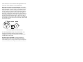
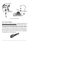
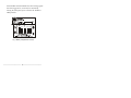
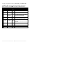
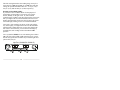
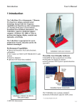
The Manufacturer:
Thought Technology Ltd.
2180 Belgrave Avenue
Montreal, Quebec, Canada
H4A 2L8
System Name:
MyoTrac™ EMG Biofeedback System
System #:
T4000P/T4001P
Device Name:
MyoTrac™ Biofeedback Unit
Device #:
SA4000P/SA4001P
⎯⎯⎯⎯⎯⎯⎯⎯⎯⎯⎯ 1 ⎯⎯⎯⎯⎯⎯⎯⎯⎯⎯⎯
•
Type BF Equipment
•
Internally powered equipment
•
Continuous operation
•
Read Instruction
•
US Federal Law restricts this device to sale by or on
order of licensed health care practitioners.
CAUTION
WARNING
•
Do not operate MyoScan sensor within 10 feet of an
operating cellular phone, similar radio transmitting
device, other powerful radio interference producing
sources such as arc welders, radio thermal treatment
equipment, x-ray machines or any other equipment that
produces electrical sparks etc.
•
Do not connect inputs or outputs of the encoder or
sensors to line powered devices.
•
All MyoTrac units are totally isolated from line (110 or
220VAC) power due to battery operation. However,
many hospitals and the FDA require that computers,
printers and any other equipment used with medical
devices be electrically isolated from line voltage to UL
or CSA medical safety standards.
•
After use, the Disposable Electrodes may be a
potential biohazard. Handle, and when applicable,
dispose of these materials in accordance with accepted
medical practice and any applicable local, state and
federal laws and regulations.
⎯⎯⎯⎯⎯⎯⎯⎯⎯⎯⎯ 2 ⎯⎯⎯⎯⎯⎯⎯⎯⎯⎯⎯
•
Radiated radio frequency electromagnetic fields can
cause performance degradation in the MyoScan
sensor. In the worst case, a RF field strength of
22mV/M can cause a degradation of 1µV in the signal
from the MyoScan sensor. Be sure to keep in mind
that a very relaxed muscle should provide an EMG
reading of approximately 1-3µV.
•
Do not use in the presence of a flammable anesthetic
mixture with air or with Oxygen or Nitrous Oxide.
•
Not to be immersed in water.
ATTENTION
•
To prevent static discharge from damaging the sensor
and/or encoders, use anti-static mats or sprays in your
working area. A humidifier may also be used to
prevent static environments by conditioning hot, dry air.
•
To prevent voiding warranty by breaking connector
pins, carefully align white guiding dot on sensor plug
with slot on sensor input.
•
Do not apply any electrode gel or equivalent directly on
the sensor snaps. Always use electrodes as a medium
between the sensor and the client.
•
Make sure to remove electrodes from sensor snaps
immediately after use.
•
Apply conductive gel only to electrodes; never put gel
directly to sensor snaps.
•
Do not plug third party sensors directly into instrument
inputs. Plug only Thought Technology Active Sensor
cable connectors into instrument inputs. All EMG
electrodes and third party sensors must be connected
to MyoScan sensors, either directly or through an
adapter.
⎯⎯⎯⎯⎯⎯⎯⎯⎯⎯⎯ 3 ⎯⎯⎯⎯⎯⎯⎯⎯⎯⎯⎯
•
Remove batteries when the device is not being used
for extended period of time. Please dispose of battery
following national regulations.
•
Sensors damaged by static electricity are not covered
under warranty! In dry climates, apply anti-static spray
on carpets each week and/or use a conductive floor
mat (available from computer stores).
CONTRAINDICATIONS
•
None
INTENDED PURPOSE
•
Biofeedback, Relaxation & Muscle Re-Education
purposes.
•
No preventative inspections required. Maintenance
must be performed by qualified personnel.
•
The supplier will make available, upon request, circuit
diagrams, component parts lists and description or
other information required for the repair of product by
qualified personnel.
NOTE
Manual # SA9601 Rev.5
⎯⎯⎯⎯⎯⎯⎯⎯⎯⎯⎯ 4 ⎯⎯⎯⎯⎯⎯⎯⎯⎯⎯⎯
Model #: MyoTrac (4000P 60Hz )
Model #: MyoTrac (4001P 50Hz )
Table of Contents
Introduction.................................................................... 6
Installing and Testing Your Battery ................................ 7
Trying Your MyoTrac for the First Time ......................... 9
Use of the MyoScan™ Sensor ...................................... 9
Front Panel Controls ................................................... 14
Battery Compartment Controls.................................... 15
Side Panel Jacks......................................................... 18
Setting the Threshold Potentiometer........................... 18
Connecting to a Voltage Monitoring Device ................ 20
Care of Your Instrument .............................................. 21
Specifications .............................................................. 22
Accessories ................................................................. 23
Warranty ...................................................................... 24
Extended Warranty Program....................................... 25
Repair Return Form..................................................... 27
Other Products and Services from Thought T............. 28
⎯⎯⎯⎯⎯⎯⎯⎯⎯⎯⎯ 5 ⎯⎯⎯⎯⎯⎯⎯⎯⎯⎯⎯
Introduction
Biofeedback is a rapidly developing scientific field that has
grown out of advances in physiology, psychology and
electronics. Ordinarily, we are unaware of the subtle internal
body activities that are part of our everyday lives.
Biofeedback uses sensitive electronics to detect and amplify
theses activities in order to bring them to awareness. By
allowing us to observe these activities, biofeedback also
allows us to learn to modify them. Since we are immediately
aware of the outcome of our attempts, we can gradually learn
to produce the results we desire.
Muscles go through a wide range of activity. Normally, we
are only aware of the muscle activity associated with
movement, such as occurs in swinging a tennis racket. Yet
much muscle activity produces no visible movement and, as
a result, goes unnoticed. EMG (electromyographic) activity
is a measure of the electrical activity in the muscles. Since
the electrical activity of the muscle increases when the
muscle is tensed and decreases when it is relaxed, EMG
biofeedback can provide information about the state of
relaxation or tension of our muscles.
Our muscles respond to threatening, stressful situations with
large increases in tension. This response is part of an old
reflex left over from a time when one had to either fight or
flee from a stressful situation in order to survive. Today,
fighting or running isn't generally appropriate. So, in most
stressful situations, there is increased muscle tension, which
cannot be dissipated by fighting or fleeing. If this high
tension continues, muscle fatigue, soreness, or even pain
may result.
Work with EMG and relaxation and tension began during
⎯⎯⎯⎯⎯⎯⎯⎯⎯⎯⎯ 6 ⎯⎯⎯⎯⎯⎯⎯⎯⎯⎯⎯
the 1920's and 1930's through the pioneering efforts of
Edmund Jacobson. Jacobson found that the more relaxed a
muscle was, the lower its EMG activity level was. He also
noted that this lowered EMG activity level was associated
with a more general subjective sense of relaxation.
EMG biofeedback is also being applied very successfully in
rehabilitation medicine - such as in regaining control of lost
muscle function, re-establishing the correct relationship
between agonist and antagonist muscles, relaxing spasmodic
activity and in strengthening weak or atrophied muscles.
While Jacobson's work marked a milestone in EMG
research, his methods of measuring EMG were crude and
cumbersome by today's standards. The MyoTrac represents a
tremendous step forward in EMG technology. Thanks to
solid state electronics and micro circuitry, equipment which
used to fill a laboratory in Jacobson's time can be replaced
today by the MyoTrac - small enough to fit in the palm of
your hand.
Installing and Testing Your Battery
Battery Insertion: We strongly recommend the use of an
alkaline or lithium 9 volt battery. You can use a rechargeable
nickel-cadmium (NiCad) battery, but keep in mind that
although NiCad batteries can be charged many times, they
last only about one quarter as long in operation as an alkaline
battery.
To insert or remove the battery, hold the device in one hand
and firmly grasp the sides of the battery compartment lid
with the other. Pull straight towards the rear of the case to
slide it off (see Figure 1). Replace the battery, being careful
to observe the proper polarity. Slide the lid back in place,
⎯⎯⎯⎯⎯⎯⎯⎯⎯⎯⎯ 7 ⎯⎯⎯⎯⎯⎯⎯⎯⎯⎯⎯
pushing gently to snap the clip.
Fig. 1 Opening the battery compartment
Note: Remove old batteries promptly to prevent corrosion.
Remove the battery if the device is not going to be used for
periods longer than one month.
Testing the Battery: To check the battery, turn the unit on,
place the threshold potentiometer to 5, and the scale-reading
switch to x1. With a Triode electrode snapped on the
MyoScan sensor, place the sensor over a muscle and tense it.
If the first yellow LED in the middle of the bargraph does
not light as the LEDs go from left to right, then change or
recharge the battery.
⎯⎯⎯⎯⎯⎯⎯⎯⎯⎯⎯ 8 ⎯⎯⎯⎯⎯⎯⎯⎯⎯⎯⎯
MyoTrac (SA4000P & SA4001P)
Trying Your MyoTrac for the First Time
Plug the MyoScan sensor into the INPUT jack. Set the
switches inside the battery compartment to: OFF, OFF,
ABV, NAR (fig. 7). Set the gain switch to the x1 position.
Turn the volume up. Set the threshold potentiometer to 10.
(fig. 6). Snap a Triode electrode on the three MyoScan
connectors (fig. 2). Hold the MyoScan sensor on your cheek
with a light pressure, placing it just below the cheekbone
(over the temporomandibular joint). Make certain that all
three electrodes contact the skin. Observe the tone and
bargraph reading as you tense and relax your jaw by
clenching your teeth. When the first yellow LED lights up,
the actual EMG reading corresponds to the threshold value
that is set on the THR. Dial, in this case, 10µV.
Use of the MyoScan™ Sensor
The MyoScan sensor incorporates sensitive electronic
circuitry to amplify the minute EMG signals directly under
the electrode connectors so that the MyoTrac's readings will
not be affected by cable movement or outside electrical
interference. For the MyoScan sensor to function properly,
electrodes must be inserted on the sensor head. There are
several choices of electrodes which can be used, depending
⎯⎯⎯⎯⎯⎯⎯⎯⎯⎯⎯ 9 ⎯⎯⎯⎯⎯⎯⎯⎯⎯⎯⎯
on the muscle site to be monitored. The disposable Triode
electrodes will be adequate for most applications.
Disposable Triode Electrodes (#T3402M): Disposable
electrodes avoid cross contamination of patients. The foambacked triangular Ag-AgCl (silver-silver chloride) Triode
electrodes can be used for scanning most muscle sites for
activity. Remove the back covering exposing the adhesive
to firmly hold the MyoScan sensor in place (see figure 2).
Generally, no skin surface preparation is required; however,
for guaranteed stability over very dry or hairy areas, clean
the target site with an alcohol wipe or apply a tiny dab of
electrode gel to each electrode. Be careful to avoid applying
the electrode gel to the skin between electrodes, which could
attenuate the signals.
Fig. 2 Triode, single and Uni-Gel electrodes
For measuring EMG activity over specific muscle sites
which are not suitably monitored by the triangular
configuration, or where a wide placement is required, an
extender cable can be used.
Extender Cable (#T8720M): Thought Technology's
450mm extender cable can be inserted directly into the
sensor head (figure 3), being careful to align the alignment
⎯⎯⎯⎯⎯⎯⎯⎯⎯⎯⎯ 10 ⎯⎯⎯⎯⎯⎯⎯⎯⎯⎯⎯
dot on the cable connector with the groove on the sensor
head.
Sensor Head
Electrode Buttons
Tho u ght
Tec h nolo gy L t d.
Align the groove
with the dot
Fig. 3 Extender Cable
When an extender cable is used, Disposable Single
Electrodes (#T3404) or Disposable Uni-Gel Electrodes
(#T3425) are snapped in the three electrode buttons (see
figure 2 & 3).
Note: To remove the electrodes, hold the sensor or the
extender cable button with one hand, place the index finger
of the other hand on the electrode and slide the thumb nail
between the electrode and the electrode snap, pry the
electrode gently out of the snap.
Sensor placement: Generally, the sensor is placed on a
muscle site so the two active electrodes are positioned
parallel to the muscle fibers (i.e. placed in line with them).
(See figure 4)
⎯⎯⎯⎯⎯⎯⎯⎯⎯⎯⎯ 11 ⎯⎯⎯⎯⎯⎯⎯⎯⎯⎯⎯
Active electrodes
!
Reference
electrode
Active electrodes
Muscle fibers
Fig. 4 Sensor Placement
Sensor jacks and plugs:
Plugs and jacks with protected pins: Thought Technology has
developed its own patented gold plated protected pin system
for all sensor and encoder plugs and jacks. The protected pins
are designed to prevent any possibility of direct skin contact
with the metallic elements that conduct the amplified signals.
They also help prevent accidental damage from attempting to
plug Thought Technology sensors and encoders to equipment
for which they were not designed.
⎯⎯⎯⎯⎯⎯⎯⎯⎯⎯⎯ 12 ⎯⎯⎯⎯⎯⎯⎯⎯⎯⎯⎯
Replacement Sensor Cable (Model T9385M)
Thought Technology sensors use a highly flexible and
lightweight cable. If, for any reason, a break should occur in
the cable, a replacement cable is available. To change cables,
tightly grip the connector plugged into the sensor with your
index finger and thumb and pull out the cable from the
sensor. Replace the cable with a new one, being careful to
align the plug with the appropriate holes in the sensor jack
(plug will align only in one direction).
Model #SA9385M
To change cables, tightly grip the connector plugged into
the MyoScan with your thumb and index, and pull gently on
the connector. Replace the cable with a new one. Be very
careful to align the notch on the cable connector with the
guiding groove on the sensor head, since the plug will align
in only one direction (see figure 5).
⎯⎯⎯⎯⎯⎯⎯⎯⎯⎯⎯ 13 ⎯⎯⎯⎯⎯⎯⎯⎯⎯⎯⎯
Guiding Notch and Groove
Fig. 5 Cable Connectors
Front Panel Controls
The front panel (see figure 6) includes controls for sound
level (VOLUME), threshold level (THR), three gain
settings, x1, x10 and x100 for ranges of .08-20, .08-200 and
.08-2000 microvolt (µV). R.M.S., respectively. Also, a
power switch lets you select OFF and either continuous
proportional tone feedback (CONT) or threshold feedback
(THR). Threshold feedback allows you to set control
parameters for the tone feedback to be enabled or disabled
when the EMG signal exceeds or falls below the threshold
setting of the threshold control. The various threshold
functions are chosen from the switch settings in the battery
compartment.
Power & Feedback
Green
Gain
Threshold
Yellow
MyoTrac (SA4000P & SA4001P)
Fig. 6 Front Panel
⎯⎯⎯⎯⎯⎯⎯⎯⎯⎯⎯ 14 ⎯⎯⎯⎯⎯⎯⎯⎯⎯⎯⎯
Note: Previous models of the MyoTrac EMG unit had only
one yellow LED and five red ones on the right. In those
units, the yellow LED corresponds to the set threshold value.
Battery Compartment Controls
Within the battery compartment are switches to set a variety
of choices as follows: (see figure 7)
WIDE/NAR bandpass (20-500 Hz. or 100-200 Hz.): Sets the
frequency range for signal detection. The 20-500 HZ.
range detects a wider range of EMG signals, but is also
prone to cardiac (EKG) interference. For this reason, it
is not recommended for monitoring sites on the back or
torso.
ABV/BLW: This switch determines if the tone feedback is
turned on when the signal exceeds (ABV) or falls below
(BLW) the threshold potentiometer setting.
ALARM/OFF: When either the 4 or 60 second switch is set,
the threshold is exceeded for at least 4 or 60 seconds, a
continuous (not proportional) tone will sound. This
alarm will sound as long as the signal stays above
threshold. As soon as the signal drops below the
threshold, the tone turns off. If the threshold is exceeded
again for 4 or 60 consecutive seconds, the warning
signal will start once more.
Note: Alarm does not work with the BLW setting.
LOCK/OFF: Works only with alarm (ALARM) on. LOCK
locks on a continuous high-pitched tone to alert the user
that the threshold level has been exceeded (if set ABV),
⎯⎯⎯⎯⎯⎯⎯⎯⎯⎯⎯ 15 ⎯⎯⎯⎯⎯⎯⎯⎯⎯⎯⎯
for more than 4 or 60 seconds. Once the warning signal
has been triggered on, it can only be canceled by
moving the front panel power switch to the CONT or
OFF positions.
ALARM
(Sec.)
60
LOCK
ON
4
OFF
OFF
BLW WIDE
ABV
NAR
Fig. 7 Battery Compartment Controls
⎯⎯⎯⎯⎯⎯⎯⎯⎯⎯⎯ 16 ⎯⎯⎯⎯⎯⎯⎯⎯⎯⎯⎯
The three threshold switches, LOCK/OFF, ALARM/OFF
and BLW/ABV are only functional when the front panel
power switch is set to THR. Possible combinations are:
LOCK/OFF
ALARM/OFF
ABV/BL
W
1
OFF
OFF
ABV
Proportional tone feedback above threshold.
2
OFF
OFF
BLW
Proportional tone feedback below threshold.
3
OFF
ALARM
ABV
Alerting tone when EMG above threshold
for > 4 or 60 seconds. (goes off immediately
when EMG goes below threshold).
4 or 60 sec.
4
OFF
ALARM
BLW
Not valid position. Alarm (ALARM) works
only for above (ABV) threshold position.
5
LOCK
ALARM
ABV
Same as condition 3; however the tone locks
on until the power switch (OFF/CONT/THR)
is turned off.
6
LOCK
ALARM
BLW
Not a valid position.
7
LOCK
OFF
ABV
Not a valid position.
8
LOCK
OFF
BLW
Not a valid position.
⎯⎯⎯⎯⎯⎯⎯⎯⎯⎯⎯ 17 ⎯⎯⎯⎯⎯⎯⎯⎯⎯⎯⎯
Side Panel Jacks
(see figure 8)
INPUT: Plug the MyoScan sensor in here.
EAR: Plugging the earphones in here disconnects the
internal speaker and sends tone feedback through the
earphones.
0-2V: Provides a 0-2 Volts output signal. The MyoTrac can
be connected to other third party device with an isolated
voltage input that accepts 0-2V. Make certain the
instrument complies with IEC 601-1.
Note: This output is the same for all the gain settings. An
output value of 2 Volts will represent 20 µV at the x1 setting,
200 µV at x10 and 2000 µV at x100.
! WARNING: Never connect your MyoTrac
to an A.C. powered device!
Setting the Threshold Potentiometer
The threshold control’s main function is to set a goal value
for the EMG signal. When that value is reached, the tone is
heard, which provides immediate feedback to reward or
inhibit a particular behavior. This control can also be used to
place the EMG signal at a desired point on the bargraph,
moving it right or left by turning the knob. It is also possible
to determine the exact EMG reading in micro Volts. As
previously mentioned, when the signal is at the first yellow
LED, EMG activity corresponds to the threshold setting.
The left-most LED indicates 1/2 the threshold value and the
right-most LED is 2 times the threshold value.
⎯⎯⎯⎯⎯⎯⎯⎯⎯⎯⎯ 18 ⎯⎯⎯⎯⎯⎯⎯⎯⎯⎯⎯
The Gain setting determines the reading range: 0-20 µV at
x1, 0-200 µV at x10 and 0-2000 µV at x100. For each gain
setting, the possible threshold values are: .5-10 µV (x1), 5100 µV (x10), and 50-1000 µV (x100) respectively.
Example of Threshold Setting:
If you want to do a feedback session for the purpose of
encouraging an increased level of activity in a specific
muscle, initially set the gain to x1. If, with a normal
contraction, the reading is near the left end of the green scale,
then you might want to set the threshold control to a lower
number (turn the knob clockwise); this will move the signal
toward the right, making it easier to reach the threshold.
Conversely, if the reading is at the top of the scale (all the
way to the right), you might want to increase the threshold
(turn the knob counterclockwise) to move the signal to the
left. If this is not sufficient, you can increase the range by
switching the scale reading switch to the x10 or x100
position.
Let’s say that the THR dial is set to 5 and the gain switch to
x10. The first yellow LED would represent 50 µV (5 x 10),
the left most green LED would be 25 µV and the right most
yellow LED, 100 µV.
MyoTrac (SA4000P & SA4001P)
25 V
50 V
100 V
⎯⎯⎯⎯⎯⎯⎯⎯⎯⎯⎯ 19 ⎯⎯⎯⎯⎯⎯⎯⎯⎯⎯⎯
Connecting to a Voltage Monitoring Device
Connect the 0-2V output jack (see figure 8) to any instrument
capable of reading from 0-2 Volts (digital voltmeter, analog
voltmeter, polygraph, integrator, etc.). Make certain the
instrument is battery operated or complies with IEC 601-1.
The output voltage will always be in the 0-2 Volt range;
however, the actual EMG level in microvolt RMS is
dependent upon the Gain setting. Range values are obtained
by multiplying the output voltage reading as follows:
Switch = x1, multiply by 10
Ex: Voltage = 0.9; EMG = 9 µV
Switch = x10, multiply by 100
Ex: Voltage = 1.5; EMG = 150 µV
Switch = x100, multiply by 1000
Ex: Voltage = 1.1; EMG = 1100 µV
Fig. 8 Side Panel Jacks
⎯⎯⎯⎯⎯⎯⎯⎯⎯⎯⎯ 20 ⎯⎯⎯⎯⎯⎯⎯⎯⎯⎯⎯
Care of Your Instrument
Basically, no maintenance, other than cleaning, is required.
Any surfaces, which come in contact with skin, should be
cleaned after each use by wiping with a damp cloth. If
conductive gel is used, use precaution not to apply any gel
on the sensor head. If gel gets inside the sensor’s electrode
connectors, clean immediately with a moistened Q-tip to
remove the gel.
IMPORTANT POINTS TO REMEMBER:
" Protect from static electricity: The MyoTrac and
MyoScan are sensitive electronic instruments, and should be
handled as such. Damage can occur if used in dry, carpeted
areas without a static mat or a static guard product sprayed
on the carpets.
# Connect and disconnect with care: When unplugging
the sensor from the MyoTrac or the sensor cable from the
sensor head, be careful to avoid pulling on the cable. Instead,
grip the connector firmly and pull straight out. Always make
sure to align the notch on the cable connectors (indicated by
a dot) with the guiding groove. Never force a connector in
the socket.
$ Always remove the electrodes: Do not leave the
electrodes connected to the sensor head when the device is
not in use as this could cause corrosion damage to your
equipment.
% Remove batteries promptly: The MyoTrac is battery
operated. To prevent corrosion damage due to battery leak,
remove battery when not in use for long periods of time and
when battery is old.
⎯⎯⎯⎯⎯⎯⎯⎯⎯⎯⎯ 21 ⎯⎯⎯⎯⎯⎯⎯⎯⎯⎯⎯
Specifications
MyoTrac SA4000P/SA4001P Hardware Specifications
Size (approx.)
Weight (approx.)
Input Impedance
Signal Input Range x1
Signal Input Range x10
Signal Input Range x100
CMRR 20 – 500 Hz (approx.)
CMRR @ 60 Hz (approx.)
Channel Bandwidth (Wide)
Channel Bandwidth (Narrow)
Signal Output Range
Supply Voltage
Current Consumption
Battery Life (Alkaline)
Low Battery Warning
Accuracy
61mm x 112mm x 25mm
(2.4” x 4.4” x 1”)
73g (2.5oz)
1,000,000MΩ
in parallel with 10pF
0 – 20µV
0 – 200µV
0 – 2000µV
130dB
180dB
20Hz ±5Hz – 500Hz ±50Hz
100Hz ±10Hz – 200Hz ±20Hz
0V – 2V
7.4V – 9.6V
10mA – 3mA /+5mA
40 Hours minimum
7.4V
±5% and ±0.3mV
⎯⎯⎯⎯⎯⎯⎯⎯⎯⎯⎯ 22 ⎯⎯⎯⎯⎯⎯⎯⎯⎯⎯⎯
Accessories
(T9385M)
Cable, replacement Protected Pin (48in.)
(T8720M)
MyoScan Sensor Extender Cable (450mm).
(T3402M)
Disposable Adhesive Triode Electrodes. (100)
(T3404)
Disposable Single Electrodes. (300)
(T3425)
Disposable Uni-Gel Electrodes. (100)
(SA3404)
MyoTrac Accessory Kit: Includes 15 Triode
Electrodes, 30 Single Electrodes, 1 sensor
Extender Cable and 1 EMG Headband.
To Order in U.S.A.:
Call 1-800 361-3651 (sales only)
or call
(514) 489-8251 (sales and technical support)
Fax:(514) 489-8255
E-Mail: [email protected]
⎯⎯⎯⎯⎯⎯⎯⎯⎯⎯⎯ 23 ⎯⎯⎯⎯⎯⎯⎯⎯⎯⎯⎯
Warranty
MyoTrac and MyoScan and all equipment including optional
items are guaranteed to be free from defects in material and
workmanship for 1 year from the date of purchase. The
MyoScan interconnect cable is guaranteed for 90 days.
During this time, in the unlikely event that repair is
necessary, Thought Technology Ltd. will repair or replace
your MyoTrac or MyoScan, free of charge.
This warranty does not apply to damage caused by static
electricity, corrosion due to battery leaks or physical damage
to the MyoTrac or the MyoScan sensor incurred through
accident, alteration or misuse of the equipment.
For repairs or returns:
Please call the Thought Technology technical support department
for a Return Authorization (R.A.) number before sending any
equipment to us.
Send the unit postage prepaid and insured, with proof of purchase.
Please provide a detailed description of the problem and write your
phone number and address clearly. (See the form on the following
page)
In U.S.A.
Thought Technology Ltd.
Cimetra Industrial Park
8396 Route 9
West Chazy NY 12992
Canada and all other
countries
Thought Technology Ltd.
2180 Belgrave Ave.,
Montreal, Quebec
Canada H4A 2L8
Tel: (514) 489-8251
⎯⎯⎯⎯⎯⎯⎯⎯⎯⎯⎯ 24 ⎯⎯⎯⎯⎯⎯⎯⎯⎯⎯⎯
Extended Warranty Program
An Extended Warranty program is available directly
through Thought Technology Ltd. and its authorized
service dealers/distributors. The program provides for an
additional two years of warranty coverage, extending the
one year warranty to three years.
All Extended Warranty Terms and Conditions apply to the
second and third year of ownership and take effect following
the regular one year warranty period. The coverage includes:
Hardware, accessories and disposables
•
Replacement or repair of unit(s), sensor(s), cable(s) and
extender cable(s).
•
Replacement or repair of unit’s carrying case and
accessories (e.g. headphones, connectors, etc.)
•
Maximum of five (5) days turnaround once equipment is
received (excluding weekends and holidays).
Software
•
Updates, upgrades and maintenance releases of software
products as these become available. Updates to user
manuals and other software documentation may also be
provided when applicable.
•
Telephone support, available Monday to Friday from
9:00 AM to 5:00 PM, excluding Canadian Legal
Holidays.
⎯⎯⎯⎯⎯⎯⎯⎯⎯⎯⎯ 25 ⎯⎯⎯⎯⎯⎯⎯⎯⎯⎯⎯
•
A 24-hour facsimile service, an Internet E-mail address
and a World Wide Web site are also available for
technical support services.
Terms & Conditions
• The price of the extended warranty program is as per the
Extended Warranty Price Lists (MAR321US$ and
MAR322 CDN$). Contact us for latest price list.
• Purchase of the extended warranty must be made within
30 days of the original purchase, and must be paid in
full.
• To enroll, the customer is asked to send a copy of their
original invoice. A new agreement will be signed with
the customer listing the products covered under extended
warranty, and the serial numbers of the units and/or
sensors.
• TTL products will be maintained and supported,
provided they are used only with the standard operating
system and hardware provided by computer vendors, as
specified in the TTL user manual.
Call us or see document: Extended Warranty Terms
and Conditions (MAR105) for additional details.
⎯⎯⎯⎯⎯⎯⎯⎯⎯⎯⎯ 26 ⎯⎯⎯⎯⎯⎯⎯⎯⎯⎯⎯
Repair Return Form
(Remove and include with the unit)
Name
______________________________________________
Company
___________________________________________
Address
____________________________________________
Phone #
____________________________________________
Fax #
____________________________________________
E-Mail
____________________________________________
Date Purchased
______________________________________
Retailer
_________________________________________
Model #
_____________________________________________
Serial # MyoTrac ________________________________________
Serial # MyoScan
____________________________________
Return for credit (less than 30 days) YES_________NO________
Return for repair (clearly state problem)
_____________________________________________________
_____________________________________________________
_____________________________________________________
_____________________________________________________
_____________________________________________________
Please include a copy of original invoice & return to the
address on the warranty page.
⎯⎯⎯⎯⎯⎯⎯⎯⎯⎯⎯ 27 ⎯⎯⎯⎯⎯⎯⎯⎯⎯⎯⎯
Other Products and Services from
Thought T
Other Products and Services from
Thought Technology Ltd.
ProComp∞™/BioGraph∞®
Versatile eight-channel computerized monitoring system. Able to
monitor up to 8 channels simultaneously including EMG, EEG, skin
conductance, temperature, heart rate, blood volume pulse,
respiration and voltage inputs from other instruments.
Thought Technology's active sensors provide unmatched signal
fidelity while our fiber optic cable provides complete safety and
signal accuracy.
Ask one of our representatives for a demo diskette.
⎯⎯⎯⎯⎯⎯⎯⎯⎯⎯⎯ 28 ⎯⎯⎯⎯⎯⎯⎯⎯⎯⎯⎯