1
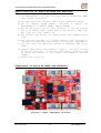
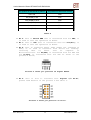
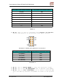
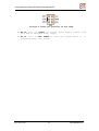
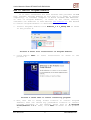
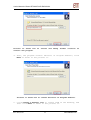
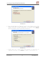
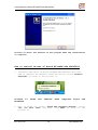
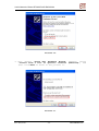
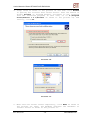
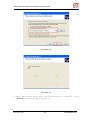
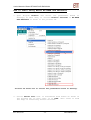
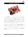
User’s Manual of Board ET-BASE AVR EASY32U4
ET-BASE AVR EASY32U4
This Arduino is Open Source that is the development project
of AVR MCU; when it is published publicly, it is widespread
rapidly and most people admire this project. It continues
developing Software and nowadays (July, 2012) the Program Arduino
has been developed to be Version Arduino 1.0.1. Moreover, it also
continues
developing
and
improving
Hardware;
it
improves
efficiency of this program to support the application with CHIP
AVR Microcontroller No.ATmega32U4. A distinctive feature of this
Board number is USB Controller insides; so, user can develop
program by downloading through Port USB of Microcontroller
ATmega32U4 directly without using any Chip USB TO SERIAL such as
No.FT232RL, unlike the previous board version.
Arduino has developed the Hardware Board to support the
application; it identifies the code as Arduino Leonardo. It
distributes and publishes details of Hardware publicly; so,
customers can further develop by one self. However, structure of
this Chip is DIP SMD, so it is difficult for some customers who
require making or creating board for themselves.
ETT has developed this ATmega32U4 to be Board and its
structure is similar to Arduino Leonardo called “ET-BASE AVR
EASY32U4”. In this case, it designs Pin I/O according to the
standard of ETT.
ETT CO.,LTD
-1-
www.etteam.com
User’s Manual of Board ET-BASE AVR EASY32U4
Specifications of Board ET-BASE AVR EASY32U4
•
•
•
•
•
•
•
•
•
Use ATmega32U4 to be MCU on board; RUN by Frequency 16MHz
from Crystal Oscillator
Has USB Controller insides, USB 2.0 Full Speed/Low Speed
Has 32 KBytes FLASH Memory (Reserved 4
BOOTLOADER), 2.5 KBytes SRAM/1 KBytes EEPROM
KBytes
for
Has 24 PIN Digital I/O in total (D0-D23); it can set Digital
I/O to be Analog Input (10Bit ADC) 12-CH (A0-A11), PWM 7-CH,
SPI 1-CH, I2C 1-CH, USART 1-CH
Has Circuit Line Driver for RS232 Serial Port Communication
1-CH
Can develop program on Program Arduino and program it
instantly through Port USB, without any external Programmer.
Can run under the Operating System of Windows, MAC OS X,
Linux
Support application with External Supply 7-12V that is both
AC and DC. Moreover, it can use Power Supply from Port USB
if using the current is not higher than 500mA by setting
Jumper.
Board size: 8 x 6 cm.
Components of Board ET-BASE AVR EASY32U4
Picture 1 shows components of board.
ETT CO.,LTD
-2-
www.etteam.com
User’s Manual of Board ET-BASE AVR EASY32U4
•
•
•
•
No.1: This is Connector DC-JACK to receive external Power
Supply 7-12V. It is free to arrange this connector in any
type because ET-BASE AVR EASY32U4 has Circuit that prevents
Connector Power Supply from converting.
No.2: This is Connector USB to interface with computer; it
is used to communicate data and develop program.
No.3: This is LED to show status of receiving data(RX) and
transmitting data(TX) for board.
No.4: This is Port to interface with Analog Input A0-A5 or
Digital I/O D18-D23 as shown in the picture 2 and table 1
below;
Picture 2 shows pin position of A0-A5.
Pin position in the format of Arduino
A0 or D18
A1 or D19
A2 or D20
A3 or D21
A4 or D22
A5 or D23
Pin position in the format of AVR
PF7
PF6
PF5
PF4
PF1
PF0
Table 1
•
No.5: This is Port to interface with Digital I/O D8-D13 as
shown in the picture 3 and table 2 below;
Picture 3 shows pin position of D8-D13.
ETT CO.,LTD
-3-
www.etteam.com
User’s Manual of Board ET-BASE AVR EASY32U4
Pin position in the format of Arduino
D8 or A8
D9 (PWM) or A9
D10 (PWM) or A10
D11 (PWM)
D12 or A11
D13 (PWM)
Pin position in the format of AVR
PB4
PB5
PB6
PB7
PD6
PC7
Table 2
•
•
•
No.6: This is Switch HWB that is interfaced with Pin PE2; it
is used to test the operation of Board.
No.7: This is LED that is interfaced with Pin D13(PC7); it
is used to test the operation of Board.
No.8: This is Connector RS232 4PIN (under the standard of
ETT); it is used to interface with device for sendingreceiving
data
by
RS232
such
as
computer
or
Microcontrollers. Pin D0(PD2) is interfaced with Pin RXD and
Pin D1(PD3) is interfaced with Pin TXD as shown in the
picture 4 below;
Picture 4 shows pin position of Signal RS232.
•
No.9: This is Port to interface with Digital I/O D0-D7;
please read details in the picture 5 and table 3.
Picture 5 shows pin position of D0-D7.
ETT CO.,LTD
-4-
www.etteam.com
User’s Manual of Board ET-BASE AVR EASY32U4
Pin position in the format of Arduino
D0 (RX)
D1 (TX)
D2 (SDA)
D3 (SCL,PWM)
D4 or A6
D5 (PWM)
D6 (PWM) or A7
D7
Pin position in the format of AVR
PD2
PD3
PD1
PD0
PD4
PC6
PD7
PE6
Table 3
•
No.10: This is Port to interface with Digital I/O D14-D17;
please read details in the picture 6 and table 4 below.
Picture 6 shows pin position of D14-D17.
Pin position in the format of Arduino
D14 (MISO)
D15 (SCK)
D16 (MOSI)
D17 (RXLED)
Pin position in the format of AVR
PB3
PB1
PB2
PB0
Picture 4
•
•
•
No.11: This is Switch RESET to start the operation of MCU.
No.12: This is MCU No.ATmega32U4 that is AVR MCU from ATMEL.
No.13: This is Port ICSP(6PIN); it is used to download HEX
File into MCU by external Programmer as shown in the picture
7.
ETT CO.,LTD
-5-
www.etteam.com
User’s Manual of Board ET-BASE AVR EASY32U4
Picture 4 shows pin position of Pin ICSP.
•
•
No.14: This is Jumper to choose Power Supply either from
Port USB or External Power Supply.
No.15: This is LED POWER to show the status while it is
providing power into board.
ETT CO.,LTD
-6-
www.etteam.com
User’s Manual of Board ET-BASE AVR EASY32U4
How to install Program Arduino
It is more convenient for user because ETT provides CD-ROM
that includes Program Arduino as file and it is ready to install
completely; it includes examples of Board ET-BASE AVR EASY32U4.
In case of Program Arduino, if there is the latest version,
customers can download it from website www.arduino.cc. The method
to install Program Arduino is described below;
1. Install Program; double-click Arduino_1.0.1_Setup.exe as shown
in the picture 8.
Picture 8 shows file installation of Program Arduino.
2. Click Button
picture 9.
Next
to
start
installation
as
shown
in
the
Picture 9 shows when it starts installing program.
3. Now, user has to setup folder location to install Program
Arduino; user can choose any preferable location or install
program according to the Default Value that is C:\Program
Files\Arduino 1.0.1. Then, click Next as shown in the picture
10.
ETT CO.,LTD
-7-
www.etteam.com
User’s Manual of Board ET-BASE AVR EASY32U4
Picture 10 shows how to
install the program.
choose
and
setup
folder
location
to
4. Then, the program creates Shortcut of Program Arduino; click
Next as shown in the picture 11.
Picture 11 shows how to create Shortcut of Program Arduino.
5. Click Create a desktop icon to create ICON on the desktop, and
then click Next as shown in the picture 12.
ETT CO.,LTD
-8-
www.etteam.com
User’s Manual of Board ET-BASE AVR EASY32U4
Picture 12
6. Now, the program is ready to install file and it also shows
values that user have already set in the previous step as
shown in picture 13. When everything is correct, click Install
and the program starts installing instantly.
Picture 13
7. Please wait for a while until the process of installing is
complete; and then click Finish as shown in the picture 14.
ETT CO.,LTD
-9-
www.etteam.com
User’s Manual of Board ET-BASE AVR EASY32U4
Picture 14 shows the feature of the program when the installation
is complete.
How to install Driver of Board ET-BASE AVR EASY32U4
1. Interface USB Cable of Board ET-BASE AVR EASY32U4 with Port
USB of computer PC; Windows found new device called “Arduino
Leonardo” as shown in the picture 15.
Picture 15
Hardware.
shows
the
feature
when
computer
found
new
2. Now, it shows the window “Found New Hardware Wizard”; choose
“No, not this time” and then click Next as shown in the
picture 16
ETT CO.,LTD
-10-
www.etteam.com
User’s Manual of Board ET-BASE AVR EASY32U4
Picture 16
3. Now, Window “Found New Hardware Wizard” appears; choose
“Install from a list or specific location (Advanced)”, and
then click Next as shown in the picture 17.
Picture 17
ETT CO.,LTD
-11-
www.etteam.com
User’s Manual of Board ET-BASE AVR EASY32U4
4. Setup value as shown in the picture 18 and then click Browse
to specify the location that stores Driver. User can search in
Folder Drivers of Program Arduino according to the location
that has installed program; in this case, it is C:\Program
Files\Arduino 1.0.1\drivers as shown in the picture 19; and
finally, click OK.
Picture 18
Picture 19
5. When user has chosen values completely, click Next as shown in
the picture 20. Then, the Windows searches the Hardware to
install Driver as shown in the picture 21.
ETT CO.,LTD
-12-
www.etteam.com
User’s Manual of Board ET-BASE AVR EASY32U4
Picture 20
Picture 21
6. When the window shows that the installation is complete, click
Finish as shown in the picture 22.
ETT CO.,LTD
-13-
www.etteam.com
User’s Manual of Board ET-BASE AVR EASY32U4
Picture 22
7. Next, the window “Found New Hardware Wizard” appears again,
choose “No, not this time”; and then, click Next as shown in
the picture 23.
Picture 23
8. The Window “Found New Hardware Wizard” appears, choose
“Install from a list or specific location (Advanced)”; and
then, click Next as shown in the picture 24.
ETT CO.,LTD
-14-
www.etteam.com
User’s Manual of Board ET-BASE AVR EASY32U4
Picture 24
9. Choose the Driver location; it normally remembers
value, click Next as shown in the picture 25.
the
old
Picture 25
10. When the window shows that the installation is complete, click
Finish as shown in the picture 26.
ETT CO.,LTD
-15-
www.etteam.com
User’s Manual of Board ET-BASE AVR EASY32U4
Picture 26
11. User can check if the installation of Driver of ET-BASE AVR
EASY32U4 is complete; click “Control Panel → System”, choose
Hardware and Device Manager. In this case, user can see the
additional lists of Hardware Arduino Leonardo and USB Human
Interface Device as shown in the picture 27.
Picture 27
completely.
ETT CO.,LTD
shows
the
feature
-16-
when
it
installs
the
Driver
www.etteam.com
User’s Manual of Board ET-BASE AVR EASY32U4
How to start using Board ET-BASE AVR EASY32U4
1. Open Program Arduino and choose the preferable board to
develop; in this case, it chooses Arduino Leonardo or ET-BASE
AVR EASY32U4 as shown in the picture 28.
Picture 28 shows how to choose the preferable board to develop.
2. Choose Serial Port that is interfaced with board as shown in
the picture 29; in this case, it is COM5. This value is from
the step of installing Driver of board.
ETT CO.,LTD
-17-
www.etteam.com
User’s Manual of Board ET-BASE AVR EASY32U4
Picture 29 shows how to choose Serial Port.
3. Open the example program of Board ET-BASE AVR EASY32U4 that is
provided by ETT as shown in the picture 30. In this case, we
would like to illustrate the example of KeyboardMessage; the
operation of this program is to set Board ET-BASE AVR EASY32U4
to be Keyboard of computer.
Picture 30 shows an example program of board.
4. Click Button Verify to check and compile the program as shown
in the picture 31. If the written program has not any error,
it shows the message “Done compiling” as shown in the picture
32.
ETT CO.,LTD
-18-
www.etteam.com
User’s Manual of Board ET-BASE AVR EASY32U4
Picture 31 shows how to check program.
Picture 32 shows the result of checking program and there is no
any error.
5. Click Button Upload to program data into board as shown in the
picture 33. If there is no any error after programmed data, it
shows the message “Done Uploading” as shown in the picture 34.
Picture 33 shows how to program data into board.
ETT CO.,LTD
-19-
www.etteam.com
User’s Manual of Board ET-BASE AVR EASY32U4
Picture 34 shows the result when it programs data completely.
6. Next, open Program Text Editor such as Notepad and press
Switch SW2(SWB) on Board ET-BASE AVR EASY32U4, it shows
message on the window of Program Notepad as shows in the
picture 35.
Picture 35 shows the operating result of program.
ETT CO.,LTD
-20-
www.etteam.com
+
+
1
2
3
4
5
6
+5V
+5V
+5V
16
D16(MOSI)
SW1
RESET
15
ICSP
V+
C1V-
100nF 5
U1
ATMEGA32U4
+
bead
C4
100nF
C3
10uF
C5
100nF
C6
100nF
7
2
6
+5V
B
1
2
3
4
R5
1M
R3
R4
3
4
22R
22R
C11
16
22pF
C10
100nF
22pF
C13
10nF
C12
C9
10uF
Y1
17
16MHz
J2
C
PC6/OC3A/OC4A
PC7/ICP3/CLK0/OC4A
VBUS
UVCC
UCAP
PD0/OC0B/SCL/INT0
PD1/SDA/INT1
PD2/RXD1/INT2
PD3/TXD1/INT3
PD4/ICP1/ADC8
PD5/XCK1/CTS
PD6/T1/OC4D/ADC9
PD7/T0/OC4D/ADC10
C8
1uF
+
VBUS
DD+
GND
+5V_USB
F1
500mA
SH1
SH2
USB
J1
USB
VCC
VCC
AVCC
AVCC
AREF
5
15
23
35
43
1
2
XTAL2
XTAL1
PE2/HWB
PE6/INT6/AIN0
PF0/ADC0
PF1/ADC1
PF4/ADC4/TCK
PF5/ADC5/TMS
PF6/ADC6/TDO
PF7/ADC7/TDI
UGND
GND
GND
GND
GND
31
32
D5
D13
18
19
20
21
25
22
26
27
D3(SCL)
D2(SDA)
D0(RXD)
D1(TXD)
D4
TXLED
D12
D6
33
1
HWB
D7
41
40
39
38
37
36
A5
A4
A3
A2
A1
A0
D0(RXD)
14
7
13
8
RS232
+5V
LED3
LED2
D13
R9
D0(RXD)
D2(SDA)
D4
D6
RX
R10
1k
+5V
R12
4k7
J6
LED4
TX
1k
R11
1k
1
3
5
7
9
1
3
5
7
9
5
7
9
1
C14
C15
4
100nF
220uF/25V
1
VIN
CONT
VO
GND
100nF
2
R6
1k
LOGO ETT
470uF/16V
3
2
4
6
8
10
A1
A3
A5
C
1
3
5
7
9
A0-A5,D18-D23
C17
3
1
2
A0
A2
A4
+5V
LED1
PWR
C16
D15(SCK)
D17(RXLED)
J9
J11
HWB
2
+
+
2
4
6
8
10
D14-D17
1
2
+5V
JP1
POWER SELECT
+
-
D9
D11
D13
J8
D14(MISO) 1
D16(MOSI) 3
R13
330R
TXLED
U3
KIA278R05
2
4
6
8
10
D8-D13
1
2
3
+5V_USB
D
D1
DF1504
4
B
J7
D8
D10
D12
J10
3
2
1
2 D1(TXD)
4 D3(SCL)
6
D5
8
D7
10
D0-D7
SW2
HWB
+5V
J3
7-12VDC
1
2
3
4
R8
1k
+5V
AREF
DD+
D17(RXLED)
D15(SCK)
D16(MOSI)
D14(MISO)
D8
D9
D10
D11
T1IN
T1OUT
T2IN
T2OUT
R1OUT
R1IN
R2OUT
R2IN
+5V
L1
8
9
10
11
28
29
30
12
+5V
J4
+5V
14
34
24
44
AREF 42
C7
100nF
PB0/SS/PCINT0
PB1/PCINT1/SCLK
PB2/PDI/PCINT2/MOSI
PB3/PDO/PCINT3/MISO
PB4/PCINT4/ADC11
PB5/PCINT5/OC1A/OC4B/ADC12
PB6/PCINT6/OC1B/OC4B/ADC13
PB7/PCINT7/OC0A/OC1C/RTS
11
10
12
9
D17(RXLED)
+5V
RESET
TXLED
13
A
100nF
C22
C2-
2
1
C2
100nF
R7
1k
D1(TXD)
100nF
6
4
3
R2
330R
C1
100nF
2
C2+
1
2
+5V
C20
C1+
100nF 3
C21
4
C18
100nF
U2P
3
4
RESET
2
4
6
VCC
A
1
1
3
5
D14(MISO)
D15(SCK)
RESET
R1
4k7
GND
D2
LL4148
U2
ICL3232
C19
J5
Project Title:
Sheet Title: ET-BASE AVR EASY32U4
Size: A4
Drawn By:
ETT CO., LTD.
REV:
Date: 7/5/2012 12:12:08 PM
Sheet: 1/1
5
6
D