1
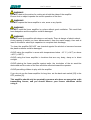
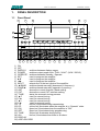
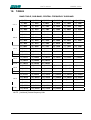
EXPERT 1K-FA
1KW SOLID STATE FULLY AUTOMATIC
LINEAR AMPLIFIER
USER’S MANUAL
User’s manual
EXPERT 1K-FA
Main index
IMPORTANT ......................................................................................................................................................4
PRECAUTIONS..................................................................................................................................................4
UNPACKING ......................................................................................................................................................6
1.
PANEL DESCRIPTION ....................................................................................................................7
1.1
Front Panel .......................................................................................................................................7
1.2
Rear Panel........................................................................................................................................8
2.
GENERAL INFORMATION ..............................................................................................................9
2.1
Power supply ....................................................................................................................................9
2.2
Input / Output....................................................................................................................................9
2.3
ALC / RELAY / CAT..........................................................................................................................9
3.
INTERCONNECTION WITH THE TRANSCEIVER .......................................................................11
4.
USE OF THE LINEAR AMPLIFIER................................................................................................12
5.
EXTERNAL GROUND CONNECTION ..........................................................................................13
6.
ANTENNA.......................................................................................................................................13
7.
POWER SUPPLY...........................................................................................................................14
7.1
Mains cable termination..................................................................................................................14
8.
TUNER ...........................................................................................................................................16
9.
PROTECTIONS / ALARMS............................................................................................................17
10.
PROGRAMMING............................................................................................................................19
10.1
Ways to operate .............................................................................................................................19
11.
INITIAL OPERATION OF THE AMPLIFIER...................................................................................22
11.1
Initial Programming.........................................................................................................................22
11.2
Operating ........................................................................................................................................23
12.
CAT CONNECTIONS.....................................................................................................................25
12.1
CAT Connector...............................................................................................................................25
12.2
SPE.................................................................................................................................................25
12.3
ICOM ..............................................................................................................................................26
CAT CI–V Interface ........................................................................................................................26
BAND CONTROL VOLTAGE Interface..........................................................................................26
12.4
KENWOOD.....................................................................................................................................27
CAT RS232 Interface .....................................................................................................................27
CAT 5V TTL Interface.....................................................................................................................27
12.5
YAESU............................................................................................................................................28
CAT RS232 Interface .....................................................................................................................28
CAT 5V TTL Interface.....................................................................................................................28
BAND DATA Interface ....................................................................................................................29
12.6
TRANSCEIVERS OF OTHER BRANDS........................................................................................29
13
OTHER CONNECTIONS ...............................................................................................................30
13.1
ALC, RELAY CONNECTIONS .......................................................................................................30
13.2
REMOTE ON LINK.........................................................................................................................30
13.3
TX INH LINK...................................................................................................................................31
14.
TRANSCEIVER CONTROLLED WITH A PC.................................................................................32
14.1
ICOM CI-V INTERFACE................................................................................................................32
14.2
RS232 INTERFACE .......................................................................................................................33
14.3
5V TTL KENWOOD INTERFACE ..................................................................................................33
14.4
5V TTL YAESU INTERFACE .........................................................................................................34
15.
USE OF THE RS-232 PORT..........................................................................................................35
16.
MAINTENANCE .............................................................................................................................36
17.
CHARACTERISTICS / SPECIFICATIONS ....................................................................................37
18.
TABLE ............................................................................................................................................39
19.
WARRANTY ...................................................................................................................................40
Pag. 3 of 42
User’s manual
EXPERT 1K-FA
Congratulations for choosing the SPE EXPERT 1KW-FA linear amplifier It is small, and
powerful, it covers the whole frequency range from 1.8 to 50 MHz, completely
automatically. All operating conditions (frequency, antenna and tuner) may be controlled
from your transceiver. It is possible to connect it to every type of device, it is extremely
user-friendly, and offers a product which is best-in-class.
IMPORTANT
Read this instruction manual carefully before attempting to operate the linear
amplifier.
Keep this manual. It contains important safety and operating instructions for the
SPE EXPERT 1K-FA.
PRECAUTIONS
Explicit definitions
WORD
WARNING!
NOTE:
DEFINITION
Risk of danger of fire or electric shock to persons.
Possible damage to the amplifier.
Serious problems if not observed. Danger of fire or electric shock for the operator, or
damage to the equipment.
WARNING!
HIGH VOLTAGE! DO NOT disconnect an antenna from the amplifier during
transmission; Electric shock or fire is possible.
WARNING!
DO NOT modify the internal wiring of the amplifier. Any modifications will invalidate the
warranty,and may reduce the performance of the linear amplifier or damage it.
WARNING!
Before using the linear amplifier, compare the value of voltage of the local mains supply
network with the value required by the amplifier, and set it up correctly.
WARNING!
DO NOT turn ON the linear amplifier unless it has been properly grounded through the
green/yellow conductor of the mains cord. Your dealer will already have provided the
correct mains plug for your local electricity network, with the earth pin connected to that
conductor. Do not disconnect this under any circumstances, or there is a risk of severe
or fatal electric shock.
WARNING!
DO NOT use an extension cord with the AC power cable, as if it is not correctly rated
there is a risk of fire or electric shock.
WARNING!
DO NOT allow metallic objects or wires to enter inside the amplifier.
Pag. 4 of 42
User’s manual
EXPERT 1K-FA
WARNING!
DO NOT obstruct the entries for cooling air at both the sides of the amplifier.
Ensure that no object impedes the correct operation of the fans.
WARNING!
DO NOT expose the linear amplifier to rain, snow or any liquids.
WARNING!
DO NOT instal the linear amplifier in a place without good ventilation. This could limit
heat dissipation and the amplifier could be damaged.
WARNING!
DO NOT touch the amplifier with damp or wet hands. There is danger of electric shock.
Avoid opening it before you have disconnected it from the mains supply, then wait at
least 2 minutes for electrolytic capacitors to complete their discharge.
To clean the amplifier DO NOT use chemical agents like alcohol or benzene because
the plastic surfaces could be damaged.
AVOID using the amplifier in areas with temperatures below –10° C (+14°F) or above
+40°C (+104°F).
AVOID using the linear amplifier in locations that are very dusty, damp or in direct
sunlight.
AVOID placing the linear amplifier against walls, the circulation of the air would be
obstructed and the noise of the fans would be reflected toward the operator.
AVOID permitting children to play with the amplifier.
If you do not use the linear amplifier for long time, set the back main switch [I/O] to the
OFF position [O].
This amplifier should only be operated by persons who have an appropriate radio
transmitting licence, and you should observe your licence conditions whilst
using it.
Pag. 5 of 42
User’s manual
EXPERT 1K-FA
UNPACKING
Remove the packing and carefully check the contents.
If you find any damage or if there are any parts missing, contact your retailer
immediately.
Keep the shipping cartons for future transportation if required.
Accessories included in the carton
a)
b)
c)
d)
e)
f)
Transport carry bag.
2 - cables with RCA (phono) connectors for ALC, RELAY links.
1 - standard RS232 cable.
2 -15 pole connectors (DB-15) for CAT links.
User manual.
Spare fuses:
1 – 12.5 A.
1 – 0,5 A.
1 - 20 A (USA and Japan only).
1 - 1 A. (USA and Japan only).
g) Spare air filter.
h) Certificate of compliance and warranty form.
f
c
b
d
g
a
e
h
Pag. 6 of 42
User’s manual
1.
PANEL DESCRIPTION
1.1
Front Panel
17
16
18
EXPERT 1K-FA
25
4
Fully Automatic
15
2
Linear Amplifier
L
L
OFF
ON
C
C
POWER
DISPLAY
14
ALL
TUNE
SET
INPUT
BAND
BAND
ANT
CAT
SET
Expert 1K - FA
23
3
OPERATE
TUNE
24
1
22
26
9
ON
OP
5
TX
1.8 -50 MHz Solid State
10
11
12
13
8
7
6
21
20
1) ON
2) OFF
3) DISPLAY
switches between display pages.
4) POWER
switches output power from “FULL / HALF“ (1KW / 500 W).
5) OPERATE switches between Standby / Operate.
6) SET
used to program the amplifier.
7) ►▼
used to program the amplifier.
8) ◄▲
used to program the amplifier.
9) INPUT
selects one of the two inputs of the amplifier.
10) ◄ BAND
switches bands manually (downward in frequency).
11) BAND ►
switches bands manually (upward in frequency).
12) ANT
shows the current Antenna / Band setting.
13) CAT
shows the current CAT interface setting.
14) TUNE:
starts the automatic tuning process.
15) ◄ C
used for manual tuning.
16) C ►
used for manual tuning.
17) ◄ L
used for manual tuning.
18) L ►
used for manual tuning.
19) TX
red led, illuminates during transmission.
20) OP
yellow led, illuminates when the amplifier is in “Operate” state.
21) ON
green led, illuminates when the amplifier is “ON”.
22) SET
green led, illuminates during programming.
23) TUNE
yellow led, illuminates during tuning.
24) ALL
red led, illuminates when there is an alarm.
25) DISPLAY
26) AIRFLOW GRID
Pag. 7 of 42
19
User’s manual
1.2
EXPERT 1K-FA
Rear Panel
1
2
WARNING
- NEVER disconnect any antenna dunring transmittion
- NEVER apply AC voltage until the amplifier is grounded
- NEVER remove the cabinet with AC cable connected
ANT 3
ANT 2
ANT 1
INPUT 1
ANT 4
INPUT 2
3
ON
I
O
11
AC
FUSE 1
FUSE 2
CAT
RELAY
ALC
IN 1
10
8
7
CAT
RELAY
ALC
RS232
IN 2
5
6
4
9
1) ANT
connectors for four possible antennas.
2) INPUT
connectors to connect two exciters.
3) FANS
4) RS 232 CONNECTOR
5) IN 1
ALC, RELAY, CAT connectors for exciter 1.
6) IN 2
ALC, RELAY, CAT connectors for exciter 2.
7) FUSE 2
fuse for the power supply; PA unit 12.5A (230 Vac), 20A (115 Vac).
8) FUSE 1
fuse for the power supply; electronic unit 0.5A ( 230 Vac ),
1A (115 Vac ).
9) AC
mains power cable.
10) GND
ground connector.
11) ON
main switch.
Pag. 8 of 42
User’s manual
2.
EXPERT 1K-FA
GENERAL INFORMATION
(Read the specific chapters for more details).
2.1
Power supply
The amplifier’s power supply is 230 / 115 Vac (230 Vac default).
The main switch [I/O] is located on the rear panel, in the [O] position all the internal
circuitry is powered off, in the [I] position (red led ON) it is possibile turn ON or turn OFF
the linear amplifier in one of the following ways:
a)
Using the [ON] /[ OFF] keys on the front panel.
b)
Applying / removing 9 -15 Vdc on pin (8) of the CAT connector.
c)
Using the RS232 port and the management software. It is possible to
download this software from the website www.linear-amplifier.com .
NOTE: When turned ON, almost all transceivers output 13,8 Vdc. With this voltage, the linear
amplifier can be turned automatically ON / OFF at the same time as the transceiver.
2.2
Input / Output
The linear amplifier has two inputs (INPUT 1, INPUT 2) to which it is possible to connect
two transceivers of any brand or type. These inputs are selected with the [INPUT] key.
It can manage up to four antennas (ANT 1, ANT 2, ANT 3, ANT 4).
The amplifier selects antennas automatically when they have been programmed.
2.3
ALC / RELAY / CAT
There are two transceiver inputs (IN 1, IN 2), to allow two different transceivers to be
connected at the same time.
ALC
Is a voltage (0, -11 Vcc) generated by the amplifier, it is used to control the
output power of the transceiver. In this way the power from the amplifier may
be automatically controlled. This link is recommended.
If the ALC port is not connected, it is ncessary to manually regulate the drive
power from the transceiver.
RELAY
This essential link allows the amplifier to be put in the transmit state. To do
that it is necessary that the inner pin of the phono connector is connected to
signal ground. This is normally done at the transceiver with either a close on
ground relay, or with a switching transistor. It is important that the voltages at
that terminal do not exceed 12 Vdc. On the transceiver this link is often called
SEND or TX GND. Refer to your transceiver manual for more details.
CAT
Thanks to this link the linear amplifier will detect the operating frequency of
the transceiver and then automatically control changes of band, antenna and
automatic antenna tuner. Most modern tranceivers have CAT control. In old
models often, analog or digital information are sent for changing band. The
SPE Expert 1K-FA, thanks to an efficient frequency counter, constantly
controls and verifies data coming from the transceiver. Automatic
management of bands, antennas and tuner can be done in the following way:
Pag. 9 of 42
User’s manual
a)
b)
c)
d)
EXPERT 1K-FA
In recent ICOM, YAESU, KENWOOD models, through CAT.
In the older ICOM models, through “Band Control Voltage”.
In the YAESU models not listed, or without CAT, through "Band
Data".
In every other case through the frequency counter.
NOTE: In case d) the CAT link with the transceiver is not needed because the
frequency is detected from the transmitted signal.
Pag. 10 of 42
User’s manual
3.
EXPERT 1K-FA
INTERCONNECTION WITH THE TRANSCEIVER
ANTENNAS
TRANSCIEVER
ANT 2
ANT 1
ANT 3
WARNING
- NEVER disconnect any antenna dunring transmittion
- NEVER apply AC voltage until the amplifier is grounded
- NEVER remove the cabinet with AC cable connected
ANT 4
SEE MANUAL
INPUT 1
INPUT 2
ON
I
ALC
O
AC
FUSE 1
FUSE 2
CAT
RELAY
ALC
CAT
RELAY
ALC
RELAY
CAT
GND
RS232
GND
1
IN 2
The diagram shows the connections with one transceiver only.To connect the second
transceiver repeat the same connections using the port “IN 2“.
For the ALC, RELAY connections, use the shielded cable (furnished) with phono RCA
connectors.
For the CAT connection, the cable must be made for the transceiver to be connected.
This cable may also be made to include ALC, RELAY ON / OFF (read the “CAT
Connections“ chapter of this manual).
For all other information about connecting a transceiver, please refer to its manual.
Pag. 11 of 42
User’s manual
4.
EXPERT 1K-FA
USE OF THE LINEAR AMPLIFIER
ANT 1
ANT 2
INPUT 1
TUNER
ANT 3
INPUT 2
AMPLIFIER
ANT 4
IN 1
CAT
IN 2
RELAY ALC
CAT
RELAY ALC
RS 232
The position of the contacts, as shown in the diagram, is the situation of the linear
amplifier in OFF state.
The linear amplifier can be used in the following ways:
1) OFF
2) STANDBY
Only direct connection between INPUT 1 and ANT 1 exists.
All the functions are activated (band change, antenna change, tuner
control) but the transmission is from the transceiver only.
3) OPERATE All the functions are activated and the transmission is using the
linear amplifier.
NOTE: Regulation of the exciter’s power is automatic through the ALC connection (the
maximum power in STANDBY, the neeted power in OPERATE).
Without the connection, you have to manually regulate the exciter’s power..
NOTE:
For continuous duty cycle transmissions (RTTY, PSKxx, SSTV, FM, AM etc.) we
recommend switching the power to “HALF“ state.
Pag. 12 of 42
User’s manual
5.
EXPERT 1K-FA
EXTERNAL GROUND CONNECTION
WARNING! Before connecting an external ground as described below, check
with a qualified electrician that your national wiring codes permit such a
connection.
To reduce TVI, BCI and other RF problems it is sometimes helpful to connect the
amplifier to a good RF ground.
The inductance of such a connection has to be low, so the connection to ground should
be as short and direct as possible. Large-section copper conductors should be used for
this purpose. Terminating the earth connection with a small metal plate is suggested.
The best solution is to have a ground stake, driven into the ground, and used only for
the radio station.
Often good results can be acheived using correct earthing clamps, connected to the
mains water supply pipe (attention, most water pipes are now in plastic).
DO NOT use central heating pipework.
AVOID the electric circuit ground of the building ( to be used for the 50/60 Hz safety
only ).
WARNING! DO NOT connect to gas pipes because there is danger of explosion !!
6.
ANTENNA
Because this is a high-power amplifier, it is necessary to use correctly-rated antennas
and feedline cables.
Take special care with antennas with traps, because trap warming can occur during
periods of high-power transmission and a high SWR can result.
Always use antennas with SWR less than 1,6:1, even if the tuner is able to overcome
some mismatches greater than 3:1.
With the tuner the PA is matched, but with a high VSWR, the cable is mismatched and
there can be consequent loss of power, heating and high voltages present.
It is suggested that suitable static protection be given to antenna feeder cables.
Pag. 13 of 42
User’s manual
7.
EXPERT 1K-FA
POWER SUPPLY
The power supply unit of the SPE Expert 1K-FA has two blocks with two separate
power transformers.
The first block has regulated and protected voltages, and powers all the electronic
circuits for command and control.
The second block powers only the PA. It has a toroidal transformer with a low magnetic
field to avoid disturbances to nearby equipment. The output voltages are 44 Vdc (on
Full-power mode) and 30 Vdc (on Half-power mode), regulated with SCRs that also
provide ‘soft start’ on switch-on.
This design was adopted as it provides maximum efficiency and therefore less heat to
dissipate.
7.1
Mains cable termination
Your dealer will ensure that a mains plug appropriate for the country of use is fitted.
If the amplifier is used in a country other than that of the original purchase, refer to your
dealer for assistance.
The default mains voltage supply of the amplifier is 230 Vac (210-250Vac).
To change this to 115 Vac (105-125 Vac). (USA customers and other countries with 115
Vac supplies) see below:
WARNING! - REMOVE THE MAINS CORD FROM THE WALL SOCKET AND
WAIT AT LEAST 2 MINUTES FOR CAPACITORS TO DISCHARGE.
Only then, remove the bottom cover, the plastic protection and connect following the
diagrams below:
Single-phase 3-wire line (210-250 VAC
The green / yellow wire from AC power cable must be
blue (white)
connected to the ground wire.
green/yellow (green)
The blue and brown wires from the AC power cable
brown (black)
can be connected to either terminal.
Single-phase 2-wire line (105-125 VAC)
The green / yellow wire from AC power cable must be
blue (white)
connected to the ground wire.
green/yellow (green)
brown (black)
The blue wire from AC power cable must be
connected to the hot (live) wire.
The brown wire from AC power cable must be
connected to the return wire.
Pag. 14 of 42
User’s manual
EXPERT 1K-FA
230 VAC
brown
brown
brown
white
white
black
black
blue
blue
blue
1 KW
TRANSFORMER
50 W
TRANSFORMER
115 VAC
brown
brown
brown
white
white
black
black
blue
blue
blue
1 KW
TRANSFORMER
50 W
TRANSFORMER
After checking your wiring, re-install the plastic protection, the bottom cover and make
sure that in “Fuse 1” there is a 1A fuse and in “Fuse 2” there is a 20A fuse (included in
the packaging). Mark the change of voltage on the back panel.
Pag. 15 of 42
User’s manual
8.
EXPERT 1K-FA
TUNER
The amplifier has an automatic tuner that handles load mismatches up to 3:1 VSWR
(2,5:1 for 50 MHz).
The circuit used is a PI – L network with excellent harmonic suppression.
The amplifier contains a look-up table with all the permitted bands.
For tuner management, antenna data and other working data are stored.
Every band has a sub-band set, and for each of those, data related to the antenna and
auto-ATU tuning is stored.
The CAT and the frequency counter detect the operating frequency and the correct
sub-band. Thanks to the stored data, the tuner and the antenna are automatically set
correctly.
For every input there is a different table. If two exciters are connected at the same time,
each exciter can have different configurations.
It is possible to use the two different tables when the amplifier operates at two different
locations. In fact it is possible to use the INPUT 1 at one and INPUT 2 on the other. In
this way repeated reprogrammings are not needed
In the US version, operation on the 12 m and 10 m bands has been inhibited following
FCC regulations. Authorized 12/10m operation of the amplifier by licensed radio
amateurs will be enabled by the dealer there in accordance with current rules.
The auto-tuner and antenna selection via the amplifier are still enabled even in 12/10m
inhibited units.
All auto-tuner functions remain, on standby, whilst using the transceiver only.
Setting of the match data to write in the tables is performed automatically by pressing
the [TUNE] key The system will then find the correct match for minimum SWR.
To achieve a better match than that achieved with the automatic tune routine (most
unlikely) it is possible to set the tuning manually by using the keys [◄ C], [C ►], [◄ L],
[L ►].
When manual tuning has been performed, it is possible to read the tuning value, the
working frequency and the associated sub-band on the appropriate screen page.
Both the types of tuning are always effected in “STANDBY“ state.
NOTE: The tuner, like all analog circuits, introduces a loss (0,8 dB max.) that may vary with
tuning conditions.The power meter of the amplifier does not show this loss as the
power is measured at the tuner input where the load resistance is always constant
(50 ohm).
NOTE: ATTENTION, When the amplifier is on the ‘STANDBY’ or ‘OPERATE’ modes, always
disable the automatic tuner in your transceiver.
Pag. 16 of 42
User’s manual
9.
EXPERT 1K-FA
PROTECTIONS / ALARMS
The SPE 1K-FA has a sophisticated protection system that constantly controls the
amplifier’s most important parameters.
These parameters are:
Temperature of the heatsink; max. / min. voltage on the PA; max. PA current; SWR;
reflected power; max voltage RF on the tuner; input power; power combiner balance.
NOTE: Unlike all the other linear amplifiers that measure only the reflected power of the
antenna, to guarantee a greater protection of the PA, the SPE amplifier measures also
the power of harmonics reflected by the band-pass filter.
NOTE: To guarantee the maximum efficiency with the same output power, the PA has three
MRF150 push-pull amplifiers connected through a combiner.
NOTE: Temperature measurement is used also to control fan speed. The thresholds where the
speed changes may be changed from NORMAL (default) or CONTEST (See the
“Programming” chapter of this manual).
The protection system is effected in two different ways:
1)
Through hardware circuits to guarantee minimum intervention time.
2)
Through software, with one of the two CPU’s, to guarantee the maximum
precision.
The two results are always compared, every difference produces a protection trip and
consequent alarm.
There are three types of protections/alarms:
a) SIMPLE
b) SERIOUS
c) FATAL
This is the most common case. An acoustic warning beep
sounds, but no operator intervention is required, as the control
system automatically restores the correct operating conditions.
When automatic system recovery is not possible (e.g. the
temperature climbs over the limits due to obstruction of the fans,
SWR is too high, etc.). In this case the amplifier switches into
standby state and the alarm is stored. Normally transmission can
continue with the exciter only.
If the amplifier is in the b) situation but the CPU is faulty or it isn’t
able to operate, the amplifier is turned OFF with no other
warning. To restart the amplifier, the main switch in the rear
panel has to be set first to [O], and then to the [I] position
NOTE: It is possibile to read the alarms file log in the standby state using the [DISPLAY] key.
To reset the alarm file log press the [TUNE] and [OPERATE] keys together.
NOTE: If the acoustic alarm is very frequent during transmission, the possible causes should
be investigated.
Pag. 17 of 42
User’s manual
EXPERT 1K-FA
NOTE: Before the temperature limits are reached, the output power will change from FULL
to HALF automatically, so that transmission with the amplifier may continue with
reduced power.
In SSB the use of the compressor, only when necessary, strongly reduces the
increase of the temperature.
If the temperature is allowed to rise further, then a “SERIOUS“ alarm will eventually
be activated.
NOTE: During a SERIOUS alarm, there is an acoustic alarm for 30 sec. Pressing the
[DISPLAY] key, the system changes to ‘STANDBY’ state immediately.
Pag. 18 of 42
User’s manual
EXPERT 1K-FA
10. PROGRAMMING
The three [SET], [◄▲] and [►▼] keys, underlined with an orange line, permit
programing the amplifier and they can used in the following way:
[SET]
[◄▲], [►▼]
Use it to open the menu page, to validate the choices and to exit from
the menu page.
Use these to select the options.
A green led illuminates during the programming process.
To program the system is very easy. You will find your programming choices confirmed
by the items shown at the lower part of the display.
NOTE: Programming is only possible in ‘STANDBY’ mode.
NOTE: Programming changes take effect only after exiting from the menu page (the green led
extinguishes).
10.1 Ways to operate
Pressing the [SET] key opens the menu page. On the display there are the following
options:
a) ANTENNA
An appropriate antenna may be assigned to each band selecting
the (ANT 1, ANT 2, ANT 3, ANT 4) connector.
If you don’t have an antenna for a particular band, input “NONE“.
Pag. 19 of 42
User’s manual
b) CAT
EXPERT 1K-FA
Allows you to program the amplifier to accept control commands from
specific transceiver types.
You may need to refer to your transceiver user manual to ensure that
it is correctly programmed to handle such a link.
Select the brand or function:
- SPE
- ICOM
- KENWOOD
- YAESU
- RS232
- NONE
No further programming is necessary, all is already
programmed for the SPE transceivers.
You need to choose between “CI-V“, or “Band Control
Voltage “ if you use the analog connection (read the “CAT
CONNECTION” chapter of this manual).
If you choose “CI-V“, you also need to choose the baud rate
which is usually 9600.
You have to choose the baud rate (almost always 9600).
If you use the CAT connection (read the “CAT
CONNECTION” chapter of this manual), select the model of
the transceiver and than select the baud rate (almost always
4800). If the model isn’t in the list, select “Band Data“ (read
the “CAT CONNECTION” chapter of this manual).
With a proper protocol it is possible to use this port not only
as a remote control but also as a CAT port (useful to link the
linear with any customer application).
Download the protocol specification from the website
www.linear-amplifier.com
Program when there isn’t a link with the Transceiver.
The amplifier frequency counter will then be used .
NOTE: If using the CAT, check that the baud rate of your transceiver is set to the same value
as you program to the amplifier.
Pag. 20 of 42
User’s manual
EXPERT 1K-FA
c) MANUAL TUNE Allows you to tune the amplifier manually. However, achieving a
better setting than that obtained by automatic tuning is very unlikely.
Set your exciter to transmit a continuous RTTY or CW signal.
Press the [◄ L], [L ►], [◄ C], [C ►] keys until you obtain the
minimum SWR.
The operating frequency and the sub-band are also shown on the
display.
NOTE: The tuning process has to be repeated for every entry (INPUT1,
INPUT 2).
d) BACKLIGHT
Regulates the backlight of the display.
NOTE: Display contrast has to be set manually. Remove the upper cover
and adjust through the hole at the upper right of the CPU card.
Adjust only if it is necessary, and use an insulated screwdriver
with care.
e) CONTEST
Permits programming two fan thresholds for normal operation
(Normal) and heavy-use (Contest).
off : Normal (65 °C, 75 °C).
on : Contest (60 °C, 70 °C).
f) BEEP
on :
off:
All acoustic warnings alarms operate and a beep confirms a
keystroke.
When you press a key there is no beep feedback, but for
all warning conditions and alarms, the acoustic warnings
are still functional.
Pag. 21 of 42
User’s manual
EXPERT 1K-FA
11. INITIAL OPERATION OF THE AMPLIFIER
Before turning ON the amplifier, the following preliminary operations are necessary:
1)
2)
3)
4)
5)
Read this manual with care.
Be sure that the amplifier is correctly set for the local mains voltage supply.
Connect the linear to ground circuit
Connect the antennas.
Connect the amplifier to the transceiver (read the “CONNECTIONS WITH
THE TRANSCEIVER” chapter of this manual)
Operate [I] the main switch on back panel, and press the [ON] key on the front panel.
Select the INPUT for the transceiver, and always carry out programming with the
amplifier in STANDBY. If you change INPUT you have to repeat this programming.
NOTE: You may have to repeat some programming if you change antenna, transceiver,etc.
NOTE: ATTENTION the ‘RELAY’ and ‘CAT’signals in some types of transceivers are only
turned ON from a transceiver MENU. Refer to the user manual.
NOTE: ATTENTION, when the amplifier is on the ‘STANDBY’ and ‘OPERATE’ modes, always
disable the transceiver auto-ATU.
11.1 Initial Programming
You must carry out the next steps in the sequence below:
a) Set Antenna.
Press [SET] and open the “ANTENNA“ menu page.
Assign an appropriate antenna for the band concerned. If you don’t have an
antenna for a band, input “NONE“.
When all the antennas are programmed, exit and go back to STANDBY.
To verify the correctness of the programming, press the [ANT] key, the
band / antenna programmed will be shown.
b) Set CAT.
Press [SET] and enter the “CAT“ menu page.
Select the transceiver brand and progress with programming according to the
type of connection between the amplifier and the transceiver (read the “CAT
CONNECTIONS” chapter of this manual).
At the end of programming, exit and go back in STANDBY.
To verify the correctness of programming, press the [CAT] key, and all the
data stored will appear on the display.
To verify the correct “CAT” operation, press [SET] and select “MANUAL TUNE”, While
changing your transceiver VFO, you should see the amplifier frequency display follow.
Then return to STANDBY.
Pag. 22 of 42
User’s manual
EXPERT 1K-FA
In the same way, if “BAND CONTROL VOLTAGE“ or “BAND DATA“ are connected,
check that the amplifier follows band changes at the transceiver.
If it does not, verify that your programming (or your link) has been done correctly.
d) Use of Automatic Tuner
To complete the programming it is necessary to match the antennas to the
amplifier by operating “TUNE“ (read the “TUNER“ chapter of this manual).
We recommend you to select each band (with available antenna) and then
program the tuner for the sub-bands within which you will operate.
efer to the table in section 18 of this manual to select the appropriate
sub-bands for your operating preferences.
Progress as follows:
1) Find the central frequency of the sub-band to tune in the table (refer to
section 18 of this manual) and set the transceiver to that frequency.
2) Press the [TUNE] key.
3) Set your transceiver to transmit a continuous tone in RTTY or CW. The
procedure for automatic tuning will start and then it will stop when SWR is
at a minimum. Sometimes it is possible to improve tuning by pressing the
[TUNE] key again.
4) Repeat the previous steps for all bands and sub-bands you want.
NOTE: If the ALC link is not used, it is preferable to reduce the transceiver power
to about 50 Watts during this operation.
NOTE: As a default, the table is programmed for standard 50 ohm out. If, for a
band, you want to reset to default programming,progress as follows:
- Go to the “ANTENNA“ menu page and set this band to “NONE“,
then exit from that page.
- Go to the “ANTENNA“ menu page again, assign the appropriate
antenna to this band, then exit from that page.
The programming will be reset for 50 ohm output.
The initial programming concludes after steps a), b), c).
11.2 Operating
You need few precautions when using the amplifier thanks its high level of automation.
SPE reminds you that it is better to lose a fraction of dB in transmitted power, by slightly
reducing the drive power, than to over-drive the amplifier and have a poor quality
transmission.
During transmission check the parameters on the display always, because SPE has
selected, designed and adjusted them with care.
SPE recommends (using the ALC link) that the transceiver should be set to its
maximum drive power.
To reduce the amplifier output, if required, it is then necessary only to set the amplifier
to “HALF” power state rather than changing the transceiver drive power.
Of course you may also regulate continuously the amplifier output power by changing
the level of drive power from your transceiver.
If less output power than 500 Watts is desired, it is preferable, for best efficiency, to
start to reduce drive from the “HALF” power state.
Pag. 23 of 42
User’s manual
EXPERT 1K-FA
SETTING DRIVE LEVELS
a) SSB:
Regulate the “MIC GAIN” of the transceiver until, speaking normally into
the microphone, the signal peaks on the display don't quite reach the
maximum rated output power. Monitoring the transmission is a good way
of checking your settings. If there is however some distortion, decrease
the “mic gain” or decrease the power of the transceiver until a small
reduction of the output power of the amplifier is seen.
b) CW:
In key down, you get the maximum output power automatically. Check the
“PW REV”. If it shows more than 120/140 Watts, decrease the power of
the transceiver until that value or less is noted.
c) RTTY, DIGITAL MODES, SSTV, FM: SPE recommends you operate in ‘HALF’ mode
because these types of transmission have a very high duty cycle. Check
“PW REV”, and if it shows more than 120/140 Watts, decrease the power
from the transceiver. In case of very heavy use, it is advisable to work in
“Contest” condition to take advantage of the greater efficiency of the fans.
d) AM
This transmission mode radiates a continuous carrier which is 25 % of its
PEP value (400W PEP AM = 100W carrier power). SPE recommends you
always operate in ‘HALF’ mode for AM. To get an output signal without
distortion, proceed as follows: transmit the AM carrier only, with your
transceiver “MIC GAIN” set to zero, and no modulation. Set the
transceiver without exceeding 125W of carrier output from the amplifier.
Then, speaking into the microphone normally, set the” MIC GAIN” of the
transceiver until the peak output power, on speech peaks, as shown on
the amplifier display, is no more than 500W. Note that because of the
modulation characteristics of AM, the average value shown will normally
be much less. SPE suggests you monitor your transmission to check that
the “MIC GAIN” setting is correct. In case of very heavy use, it is advisable
to work in “Contest” condition to take advantage of the greater efficiency
of the fans.
NOTE: If you choose to set the output power of the amplifier by varying the output power of
the transceiver, the ALC connection is not required.
NOTE: ATTENTION, never stress uselessly the amplifier with long periods in key-down, it can
be a possible cause of damage.
NOTE: ATTENTION, in SSB the use of the compressor, only when necessary, strongly reduces
the increase of the temperature.
Pag. 24 of 42
User’s manual
EXPERT 1K-FA
12. CAT CONNECTIONS
12.1 CAT Connector
In this diagram the rear panel CAT connector and pinouts are shown
1
9
2
10
3
11
4
12
5
13
6
14
7
15
8
RX 232
TX 232
BAND CONTROL VOLTAGE
RX TTL
TX TTL
KEN TTL
GND
RELAY
ALC
TX-INH
BAND A
BAND B
BAND DATA
BAND C
BAND D
REMOTE ON
DB15 F
pin n°
1
9
2
10
3
11
4
12
5
13
6
14
7
15
8
pin name
RX 232
TX 232
BAND CONTROL VOLTAGE
RX TTL
TX TTL
KEN TTL
GND
RELAY
ALC
TX - INH
DATA A
DATA B
DATA C
DATA D
REMOTE ON
Description
Used on Kenwood and Yaesu transceivers for the link with a RS-232
connection.
Analog band switch on the Icom transceivers.
Used on Icom, Kenwood and Yaesu transceivers for the CAT 5V TTL
connection.
Connect to GND if CAT 5V TTL Kenwood connection.
Signal ground.
Connected in parallel with the RCA phono RELAY connector.
Connected in parallel with the RCA phono ALC connector.
Used to improve the receive / transmit switching efficiency.
Bit A of Band Data (digital switch of band for Yaesu).
Bit B of Band Data (digital switch of band for Yaesu).
Bit C of Band Data (digital switch of band for Yaesu).
Bit D of Band Data (digital switch of band for Yaesu).
Applying a voltage from 9 to 15 Vcc, turns the amplifier ON.
Using the above information, an appropriate cable for your transceiver(s) may be
constructed, or you might wish to order a correctly made-up cable when you order your
amplifier from your local dealer. The amplifier connector is included with the
amplifier,and the transceiver connector (called “Radio” in the next diagram) is usually
supplied with the transceiver.
For connections to the Radio connector, refer to the transceiver operating manual.
12.2 SPE
In the case of SPE transceivers, it isn’t necessary to make a cable because it is
supplied with the transceiver.
Pag. 25 of 42
User’s manual
EXPERT 1K-FA
12.3 ICOM
CAT CI–V Interface
1
9
2
10
RX TTL
RADIO CONNECTOR
3
11
4
GND
12
5
13
6
14
7
15
8
DB15 M
This interface is standard for all the Icom models equipped with CAT, the cable always
terminates to a 3,5 mm. plug
BAND CONTROL VOLTAGE Interface
1
9
BAND CONTROL VOLTAGE
BAND CONTROL VOLTAGE
2
10
3
11
4
GND
GND
12
RADIO CONNECTOR
5
13
6
14
7
15
8
DB15 M
This interface is standard for all the Icom models not equipped with CAT. The change of
a voltage determines the change of band.
Pag. 26 of 42
User’s manual
EXPERT 1K-FA
12.4 KENWOOD
CAT RS232 Interface
1
9
RX 232
TX 232
(RXD)
2
(TXD)
10
RX 232
TX 232
3
11
4
GND
GND
12
RTS
13
CTS
5
6
RADIO CONNECTOR
14
7
15
8
DB15 M
The Radio connector could be DB-9 or DB-25 male connector or female connector
(read the specific manual). In the manual also verify if the RTS–CTS link is necessary.
CAT 5V TTL Interface
1
9
2
10
3
11
4
TX
RX TTL
TX TTL
KEN TTL
GND
RX
GND
12
RTS
13
CTS
5
6
RADIO CONNECTOR
14
7
15
8
DB15 M
The connector is described in the specific manual. Verify if the RTS–CTS link is
necessary.
Pag. 27 of 42
User’s manual
EXPERT 1K-FA
12.5 YAESU
CAT RS232 Interface
1
9
RX 232
TX 232
(RXD)
2
(TXD)
10
TX 232
RX 232
3
11
4
GND
GND
12
RTS
13
CTS
5
6
RADIO CONNECTOR
14
7
15
8
DB15 M
The Radio connector may be a DB-9 or DB-25 male connector or female connector
(read the specific manual). Verify from the manaul if the RTS–CTS link is necessary.
CAT 5V TTL Interface
1
9
2
10
3
11
4
RX TTL
TX TTL
TX
GND
GND
RX
12
RTS
13
CTS
5
6
RADIO CONNECTOR
14
7
15
8
DB15 M
The connector is described in the manual. Verify if the RTS–CTS link is necessary.
Pag. 28 of 42
User’s manual
EXPERT 1K-FA
BAND DATA Interface
1
9
2
10
3
11
4
GND
GND
12
5
13
6
14
7
15
BAND A
BAND B
BAND C
BAND D
BAND A
BAND B
BAND C
BAND D
8
RADIO CONNECTO
DB15 M
Without the CAT, the band is commanded by four digital signals (Band A, Band B,
Band C, Band D). Refer to the specific manual.
12.6 TRANSCEIVERS OF OTHER BRANDS
A special link is not necessary as the internal amplifier frequency counter will measure
the input frequency and will control the amplifier.
Pag. 29 of 42
User’s manual
13
EXPERT 1K-FA
OTHER CONNECTIONS
On the 15-pin connector, in addition to the CAT signals, the ALC and RELAY signals
are repeated, REMOTE ON and TX – INH are also available. If you use this connector,
in some cases, separate ALC and RELAY cables may not be necessary, or it may be
possible to turn the amplifier on / off by turning on / off the transceiver (REMOTE ON).
The following diagram shows how to integrate all transceiver control connections to the
15-way amplifier connector.
Check the transceiver handbooks for terminating that end of the cable.
13.1 ALC, RELAY CONNECTIONS
1
9
2
10
3
11
4
12
5
13
GND
GND
RELAY
ALC
GND
RELAY/SEND/TX-GND
ALC
6
14
GND
15
RADIO CONNECTOR
7
8
DB15 M
13.2 REMOTE ON LINK
1
9
2
10
3
11
4
GND
12
5
13
GND
14
13.8V
15
RADIO CONNECTOR
6
7
8
REMOTE ON
DB15 M
Pag. 30 of 42
User’s manual
EXPERT 1K-FA
13.3 TX INH LINK
Some tranceivers have a suitable input (called TX – INHIBIT, LINEAR, MUTE, etc.) that
disables transmission. To improve the receive / transmit switching efficiency it is highly
recommended, but not mandatory, to connect this input with the pin 13 of the linear
connector (TX – INH).
1
9
2
10
3
11
4
GND
GND
12
5
13
TX-INH
TX-INH
6
14
7
RADIO CONNECTOR
15
8
DB15 M
Pag. 31 of 42
User’s manual
EXPERT 1K-FA
14. TRANSCEIVER CONTROLLED WITH A PC
If the transceiver is controlled with a PC using the CAT utility, the user should consider
this situation for the link with the amplifier.
14.1 ICOM CI-V INTERFACE
ICOM
RADIO
DB15 F
LINEAR
CONNECTOR
CI-V
INTERFACE
CT 17
The plug from the amplifier has to be connected to a CI–V port of the CT17 or similar
device. The transceiver has to be connected to another CI–V port.
Pag. 32 of 42
User’s manual
EXPERT 1K-FA
14.2 RS232 INTERFACE
KENWOOD OR YAESU
RADIO CONNECTOR
RX
RX
TX
9
GND
RX 232
TX 232
1
GND
RS232
X
2
10
11
GND
4
TX
RS232
3
PC CONNECTOR
12
5
13
6
14
7
15
8
DB15 M
This type of link is the same both for Kenwood and Yaesu
On the other end of the cable it is necessary to link only GND and RX 232.
14.3 5V TTL KENWOOD INTERFACE
KENWOOD
RADIO CONNECTOR
11
4
TX
3
RX TTL
TX TTL
KEN TTL
GND
RX
10
RX
2
TX
TTL
9
GND
1
X
GND
12
5
13
TTL INTERFACE
6
14
7
PC
15
8
DB15 M
The links on the linear connector side are the same.
On the other end of the cable it is necessary to link only GND and RX TTL.
Pag. 33 of 42
User’s manual
EXPERT 1K-FA
14.4 5V TTL YAESU INTERFACE
YAESU
RADIO CONNECTOR
11
4
TX
3
RX TTL
TX TTL
RX
10
RX
2
TX
TTL
9
GND
1
X
GND
GND
12
5
13
TTL INTERFACE
6
14
7
PC
15
8
DB15 M
The links on the linear connector side are the same.
On the other end of the cable it is necessary to link only GND and RX TTL.
Pag. 34 of 42
User’s manual
EXPERT 1K-FA
15. USE OF THE RS-232 PORT
Through the RS232 port it is possibile to interface the amplifier with a PC.
It is possible to download from the website www.linear-amplifier.com the software that
permits interfacing the amplifier in a remote way, connecting the amplifier to a PC with
the supplied cable.
On the same website there is, for programmer use, a protocol specification that permits
creation of a proper software application.
NOTE: SPE doesn't take any responsibility for these applications.
Pag. 35 of 42
User’s manual
EXPERT 1K-FA
16. MAINTENANCE
The Expert 1K-FA linear amplifier doesn’t need internal maintenance because it has a
cover without ventilation holes. No tube-type EHT is used so the high voltages present
in tube amplifiers, which sometimes attract dirt, are not present.
The user has only to periodically check the cleaning of the air filter on the front panel.
The frequency of such operation depends how dusty the amplifier location is and how
much it is used. We recommend monthly cleaning of the filter.
To clean the filter
a)
Remove the front grid.
b)
Remove the filter and clean it with care.
c)
Reassemble the filter and the grid after having carefullly cleaned the
mechanical structure that includes them.
NOTE: Check the filter if an unexpected rise of temperature is noticed.
NOTE: Never operate without the filter, as dust could be deposited on the surface of the
heatsink limiting its ability to cool.
NOTE: To allow the most efficient heat-dissipation, large copper parts have been used.
Pag. 36 of 42
User’s manual
EXPERT 1K-FA
17. CHARACTERISTICS / SPECIFICATIONS
- The smallest in the world
Built-in Power supply and Automatic Antenna Tuner.
Dimension: w 28, h 14, d 32 cm. (connectors included).
Weight: approx. 20 Kg (18,5 Kg typ.).
- The most technologically advanced in the world
Two CPUs are used, one of which is dedicated to the transceiver interface
requirements (CAT).
Pi-L output circuit.
Over 13000 lines of software for performance that cannot be found in any other
amplifier.
- Fully Automatic
Easy connection with all models "ICOM, YAESU, KENWOOD" for immediate
management of the bands, tuner and antennas.
Same performance with all makes or homemade rigs.
The operator has only to move the “Frequency Tuning Knob” in the transceiver!!!
- Wide frequency coverage
1.8 MHz to 50 MHz including WARC bands (US version available).
- Fully solid state
1 KW pep SSB output; 900 W pep CW out (typ.) ; 700 W pep out. (typ.) on
50 MHz.
FULL / HALF power selected according to the operator SSB/CW power
requirement, for digital modes and for linear protection (automatic).
No heating time, immediately ready!
Virtually limitless life of the amplification devices (MOSFETs).
- Automatic Antenna Tuner built-in
Capable of matching 3:1 SWR on HF, and 2.5:1 SWR on 6 meters.
Capable of programmable switching of 4 antennas (SO239 connectors).
Bands, Antennas, Tuning conditions are changed in 10 msec.
Bands, Antennas and Tuning conditions are managed also in “STBY“ to support
the exciter only.
- Two inputs available
SO239 connectors.
- Driving Power 20 W (typ.) / 60 W ( typ.) US version
In “OPERATE“ the required drive power is automatically set with an ALC
connection and in “STANDBY“ the exciter is then automatically reset to full power.
- Very clean and low distortion output!
Spurious emissions less than -50 dB ( 50 MHz –60 dB ).
3rd order distortion (two tone test) 36 dB typ.
- Input 50 ohm always perfectly matched
SWR less than 1.2:1.
- Fully protected
Temperature, Over-Voltage, Over-Current, SWR, Reflected Power, Max RF Tuner
Voltage, Over-Drive, Amp. The correct parameters are continuously monitored.
Pag. 37 of 42
User’s manual
EXPERT 1K-FA
The same protection is realized in two different ways:
· Via hardware circuits (HW) to assure great speed.
· Via the software (SW), to assure great accuracy.
Thanks to the SW, transmit relay changeover is carried out with zero current at
the contacts.
- Full break-in operation (QSK)
- Normal / Contest operation to optimize performance
- Very quiet operation
Seven quiet three-speed cooling fans:
· 150 CFM maximum total air flow.
Temperature thresholds for speed change:
· 65 deg. and 75 deg. (normal mode).
· 60 deg. and 70 deg. (contest mode).
Noise level:
· 39 dBa at maximum blower speed.
- Continuous use
“FULL” mode: SSB unlimited, key down 3 minutes.
“HALF” mode: SSB unlimited, key down 10 minutes.
- Regulated power supply, input 230 / 115 Vac
With both input voltages the output power doesn't change.
A well designed grain-oriented, tape-wound toroidal transformer reduces
magnetic fields around the amplifier .
- The linear can be switched ON / OFF also switching ON / OFF the exciter
- With a large LCD display is possible to have a great deal of information
W pep out, V pa, I pa, W pep reflected, Power gain, Temperature, SWR, Input
setting, CAT setting, Band and other indications including an alarms log.
- Easy to operate
Powerful SW gives you a user-friendly unit.
- RS 232 port for PC control
SW is supplied to remote the linear front panel.
With a proper protocol it is possible to use this port not only as a remote control but
also as a CAT port (useful to link the linear with any customer application).
- Easy transportation
A sturdy carry-bag is supplied for “QSY, FIELD DAY, DX’ PEDITIONS etc.“.
- Certifications :
CE, (FCC are pending).
These specifications are subject to change without notice.
Pag. 38 of 42
User’s manual
EXPERT 1K-FA
18. TABLE
BAND TABLE, SUB-BAND, CENTRAL FREQUENCY SUB-BAND
160 m
80 m
40 m
30 m
20 m
17 m
15 m
12 m
10 m
[ 0] 1785
[ 1] 1795
[ 2] 1805
[ 3] 1815
[ 4] 1825
[ 5] 1835
[ 6] 1845
[ 7] 1855
[ 8] 1865
[ 9] 1875
[ 10] 1885
[ 11] 1895
[ 12] 1905
[ 13] 1915
[ 14] 1925
[ 15] 1935
[ 16] 1945
[ 17] 1955
[ 18] 1965
[ 19] 1975
[ 20] 1985
[ 21] 1995
[ 22] 2005
[ 23] 2015
[ 24] 3470
[ 25] 3490
[ 26] 3510
[ 27] 3530
[ 28] 3550
[ 29] 3570
[ 30] 3590
[ 31] 3610
[ 32] 3630
[ 33] 3650
[ 34] 3670
[ 35] 3690
[ 36] 3710
[ 37] 3730
[ 38] 3750
[ 39] 3770
[ 40] 3790
[ 41] 3810
[ 42] 3830
[ 43] 3850
[ 44] 3870
[ 45] 3890
[ 46] 3910
[ 47] 3930
[ 48] 3950
[ 49] 3970
[ 50] 3990
[ 51] 4010
[ 52] 4030
[ 53] 6963
[ 54] 6988
[ 55] 7013
[ 56] 7038
[ 57] 7063
[ 58] 7088
[ 59] 7113
[ 60] 7138
[ 61] 7163
[ 62] 7188
[ 63] 7213
[ 64] 7238
[ 65] 7263
[ 66] 7288
[ 67] 7313
[ 68] 7338
[ 69] 10075
[ 70] 10125
[ 71] 10175
[ 72] 13975
[ 73] 14025
[ 74] 14075
[ 75] 14125
[ 76] 14175
[ 77] 14225
[ 78] 14275
[ 79] 14325
[ 80] 14375
[ 81] 18075
[ 82] 18125
[ 83] 18165
[ 84] 20975
[ 85] 21025
[ 86] 21075
[ 87] 21125
[ 88] 21175
[ 89] 21225
[ 90] 21275
[ 91] 21325
[ 92] 21375
[ 93] 21425
[ 94] 21475
[ 95] 24891
[ 96] 24963
[ 97] 25038
[ 98] 27950
[ 99] 28050
[100] 28150
[101] 28250
[102] 28350
[103] 28450
[104] 28550
[105] 28650
[106] 28750
[107] 28850
[108] 28950
[109] 29050
[110] 29150
[111] 29250
[112] 29350
[113] 29450
[114] 29550
[115] 29650
[117] 49750
[118] 50250
[119] 50750
[120] 51250
[121] 51750
[122] 52250
[123] 52750
[124] 53250
[125] 53750
[126] 54250
[116] 29750
6m
NOTE: [sub-band] Central frequency KHz
Pag. 39 of 42
User’s manual
EXPERT 1K-FA
19. WARRANTY
SPE warrants to the original purchaser that this product shall be free from defects or
workmanship.
SPE warrants for two (2) years from the date of original purchaser that will provide free
of charge all parts and labor necessary to correct defects in material or workmanship.
The purchaser has to pay only the cost of shipping for warranty work.
To obtein such warranty service, the original purchaser must:
1) Complete and send to SPE, not over 30 days from the date of purchase, the
warranty registration card.
2) Notify SPE or its nearest authorized service facility, immediately the defect
discovered sending:
a) The model and the serial number of the amplifier;
b) The identity of the seller and the date of purchase
c) The description of the defect.
The warranty does not apply to any defect that SPE determines is due to:
a) Improper maintenance or repair by persons not authorised by SPE to carry out
such work, including the installation of parts or accessories that do not conform
to the quality and specifications of the original parts.
b) Misuse, abuse, neglet or improper installation.
c) Carelessness, accidental or intentional damage.
SPE warranties aforesaid items only, and the purchser shall have no remedy and no
claim for incidental or consequential damages.
Particular agreements between retailer and purchaser or particular obligations imposed
in other countries are matters for the local retailer and not for SPE.
SPE recommends you record this information:
- Model of the amplifier
- Serial number
- Date of purchse
- Name and address of the retailer
- Date of mailing of the Warranty Card.
Pag. 40 of 42
User’s manual
Notes:
Pag. 41 of 42
EXPERT 1K-FA
SPE s.r.l.
Via di Monteverde, 33 00152 Rome (Italy)
Tel. +390658209429
Fax. +390658209647
E-mail: [email protected]
Website: http://www.linear-amplifier.com
Ver. 1.2
Copyright © 2006 S.P.E. srl All Rights Reserved