1
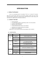
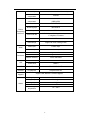
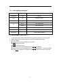
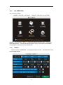
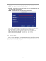
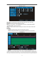
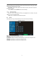
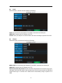
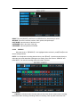
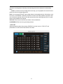
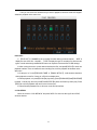
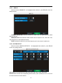
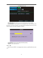
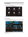
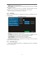
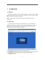
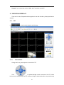
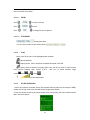
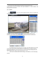
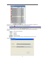
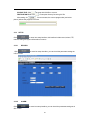
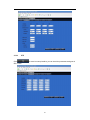
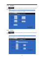
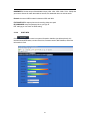
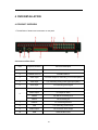
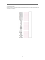
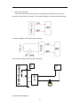
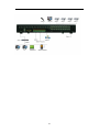
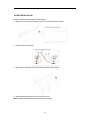
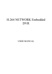
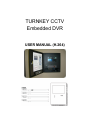
TURNKEY CCTV Embedded DVR USER MANUAL (H.264) CONTENT 1.1 PRODUCT INTRODUCE ................................................................................................................3 1.2 PRODUCT FEATURE .....................................................................................................................3 1.2.1 SPECIFICATION ........................................................................................................................3 1.2.2 BASIC WORKING PARAMETER ..............................................................................................5 1.3 ENVIRONMENT ADAPTABILITY ................................................................................................5 2 DEVICE OPERATION ............................................................................................................................6 2.1 REMOTE KEY INSTRUCTION ......................................................................................................6 2.1.1 REMOTE CONTROL ..................................................................................................................6 2.1.2 MOUSE OPERATION .................................................................................................................8 2.1.3 MENU TREE ............................................................................................................................. 10 2.2 SYSTEM OPERATION ................................................................................................................. 11 2.2.1 USER LOGIN ............................................................................................................................ 11 2.2.2 GUI OPERATION ..................................................................................................................... 12 2.2.3 DEVICES SETUP ...................................................................................................................... 21 2.2.4 SYSTEM SETUP ....................................................................................................................... 27 3 IE OPERATION .................................................................................................................................... 31 3.1 FEATURE ..................................................................................................................................... 31 3.2 USER LOGIN ................................................................................................................................ 31 3.3 OPERATION INTERFACE ........................................................................................................... 32 3.3.1 LIVE .......................................................................................................................................... 32 3.3.1.1 PTZ CONTROL ..................................................................................................................... 32 3.3.1.1.1 ZOOM ............................................................................................................................... 33 3.3.1.1.2 PTZ PRESET ..................................................................................................................... 33 3.3.1.2 PLAY .................................................................................................................................... 33 3.3.1.3 OTHER OPERATION ........................................................................................................... 33 3.3.2 REPLAY .................................................................................................................................... 34 3.3.3 SETUP ....................................................................................................................................... 36 3.3.3.1 RECORD ............................................................................................................................... 36 3.3.3.2 ALARM .................................................................................................................................36 3.3.3.3 PTZ........................................................................................................................................ 37 3.3.3.4 NETWORK ........................................................................................................................... 38 3.3.3.5 SETTING............................................................................................................................... 38 3.3.3.6 HOST INFO ........................................................................................................................... 39 4 DVR INSTALLATION .......................................................................................................................... 40 4.1 4.2 PRODUCT OVERVIEW ................................................................................................................ 40 HDD INSTALLATION .................................................................................................................. 44 5.FAQ ............................................................................................................................................................ 45 2 INTRODUCTION 1.1 PRODUCT INTRODUCE TK-4/ 8/ 16 is developed base on new platform. TK-16 is a 16 channel CIF resolution digital video recording DVR, which has local recording, playback, support triple code remote network surveillance, data backup, parameter setting, motion detection, I/O alarm setting, PTZ and USB mouse, USB2.0 backup, IE browser and back up. 1.2 PRODUCT FEATURE H.264 compression Two USB interface, USB2.0 for data backup, USB1.1 for mouse operation 2 pcses 3.5” SATA HDD at most Special file system for security 16 nature translucence GUI, note for menu selected Optimized one four channel simultaneously playback double level user management Support the live view, parameter setting and copy playback video via network. 1.2.1 SPECIFICATION Item System Device Performance Index Language Chinese/ English/ Italian GUI Graphic menu Password User password, Administrator password 16ch complex video input 1.0V p-p, impedance75Ω, BNC 2ch complex video output 1.0V p-p, impedance75Ω, BNC Video in Video out Video Audio Video display 1/4/9/16 switch Video standard PAL,25f/s, CCIR625line, 50scene NTSC,30f/s, CCIR525line, 60scene Audio input 4ch audio input, impedance 600Ω, RCA Audio output 1ch audio output, impedance 600Ω, RCA Basic electricity output Linearity electricity 3 Record style Audio video recorded simultaneously Audio compression Picture compression H.264, (VBR)/(CBR) Picture resolution CIF/ HD1/ D1 Streaming style ISO14496-10 Audio style ADPCM Video code rate CIF: 384Kbps ~ 768Kbps, 8 level optional, 1 is highest, 8 is lowest Audio code rate 32KB/s Data storage Support all kinds of storage HDD Alarm input 8 alarm input Alarm output 1 alarm output Serial interface Serial interface Support 1 RS232 Support 1 RS485 Network interface RJ45, 10M/100M Mouse USB1.1 Thumb drive USB2.0 LCD LCD 7’’/10.2’’LCD PANEL Software PC playback Playback video file Picture Proceeding and Store ADPCM Alarm Connector USB Software Upgrade Others Support USB, Network Firmware Upgrade Voltage input AC:110~240V Voltage output DC:19V@3A Voltage input Power Working temperature 16W +12V@1A without HDD 14----122°F 4 1.2.2 BASIC WORKING PARAMETER Item Parameter Remark Voltage Input 19V DC 19V. Video Impedance Input 75Ω 75Ωeach channel. Video Output 1Vp-p 1Vp-p CVBS signal 0—2V Low voltage alarm 5V-30v High voltage alarm I/O RS232 Serial port, for extend use RS485 Connect to PTZ, (Pelco-D,Pelco-P) SATA HDD 2 SATA with all capability 1.3 ENVIRONMENT ADAPTABILITY 1) 2) For the safely using DVR and prolong device life, please pay attention on following detail: When installing device, please comply with all electric product safety criterion; Power and ground: Do Not touch the power and DVR with a wet hand Do Not drop liquid on DVR Do Not put others on DVR Please use soft dry cloth when cleaning DVR, Do Not use solvents When the power line connects with jack, even Do Not startup device. There is still voltage If you Do Not use device for a long time, please take the power line away from the jack 5 2 DEVICE OPERATION In device operation, the enter key on remote control has the same function as the mouse left click. 2.1 REMOTE KEY INSTRUCTION 2.1.1 REMOTE CONTROL Handheld IR Controller Key Functions: 【0-9】keys: During setup, number keys are used to input values. For viewing channels 1, 2, 3 and 4, use 1, 2, 3 and 4 on numeric keypad 6 respectively. 【+】,【-】keys: During setup, plus and minus are used to select next or previous values. ▲, : Up, Down directional keys: Move selection up and down in setup menu. , : Left, Right directional keys: Move cursor left or right in setup menu. 【OK】: During setup, select and save entry During Playback and preview, displays the channel name, text number, driver name, event sensor item and time, year/month/date, time, GPRS/GPS info on the screen. 【PLAY】: Starts/Resumes playback from any other mode (FF, RR, Frame by Frame etc) 【SLOW】: Reduces playback speed to 1/2X、1/4X、1/8X、1/16X mode. Press PLAY to return to normal playback speed. 【PAUSE/STEP】: Freezes playback to single frame and can advance one frame at a time. To advance the frame press Pause/Step to move frame by frame. Press EXIT to return to normal playback speed. 【FWD】: Fast forward the video while playback. X2, X4, X8 modes available. Press FWD to switch, press 【PLAY】to return to normal speed; 【REV】: Reverse the video while playback, 2X, 4X, 8X modes are available. Press REW to switch, press【PLAY】 to return to normal speed; 【STANDBY】: Reset the TKDVR to Power On and Power Off mode.( Standby and start up); 【LOGIN/LOCK】: If the security is enabled in the setup, use LOGIN/LOCK key to enter the user setup. It is important to remember the password unable to do without restoration function. Log in (To enter into “User ID select” and “Password” input interface)and lock functions( To exit setup and operation) 【EXIT】: Exit to the preview or return to the last menu; 【RECORD】: Start manual record 【STOP】: Stop manual record (CAN NOT stop timer record and normal record) 【MENU】: Enter into setup interface and setup the system parameters 【PTZ】: PTZ control, press this key to enter into PTZ control interface when at single live view; 【EXTRA】【AUDIO】【MUTE】for future use. 7 2.1.2 MOUSE OPERATION You can use a mouse to operate the menu except the IR remote controller. (The operation usage is the same as PC Windows). Please insert the mouse into USB1.1. Enter into main menu: Click the right key on the live view. Click Right Key Exit the present menu: It won’t save the settings if you click the right key to exit. Exit the playback interface: Click the right key to exit when you are playback. Click the left key to enter into the setting interface. Click the left key to zoom in the window on the live view and playback video. Double click the left key can exit to the live view and playback multi-window interface. 1. Volume adjustment, color adjustment, PTZ setting and VGA border operation. It is for setting the single channel for volume adjustment, PTZ control and color adjustment. If it is multi-window, please use the left key to select the single window. 2. The remark when click the left key for volume adjustment,color adjustment,VGA border is as follow: Click Left Key a. There is and on the PTZ setting to adjust parameter, click it can make the setting for PTZ. b. There is a sticker to show the volume on the volume adjustment interface. Move the mouse to the corresponding position and click the left key, The right side of sticker will show the volume ,click “x” to exit; c. Color adjustment and VGA border operation can refer to the volume adjustment interface operation. When there are many options in the option frame, click left key to ball out down-pull menu. To click the left key on the playback interface can make >> means forward, << means REW, >>I means Slow play, I> means frame play,> means Play, X means exit. 8 Click Left or Right Key 1. In the input frame, click the left key or right key can activate the keyboard. Click the right key can make the switch of Chinese and English on the soft keyboard. The number, symbol, English can be input by clicking the mouse. 2. Pinyin also can be input by the soft keyboard when enter Chinese, the method is the same as IR remote controller. You can use the left/right key to turn over the page when check on Pinyin/Chinese word. 3. When input number, click the right key, the number soft keyboard will pop up firstly, and then use the left key to select the corresponding value. Also click the left key to exit the number keyboard. Mouse Move 1. Press the left key to move the mouse can adjust the parameter on the volume, color, and VGA border interface. And the corresponding parameter will display at the same time. 2. In the Motion Detection setting interface, you can use the left key to drag the frame to set the motion detection area. 9 2.1.3 MENU TREE You can control the DVR by a lot of menu operation. This tree will show you the menu structure and it will be in details in after chapter. 10 2.2 SYSTEM OPERATION 2.2.1 USER LOGIN 1. START-UP Connect the DC19V/3A adapter to DVR. When starting up the DVR, 【POW】LED will be on and 16 images will be displayed on the screen. If it has setup ignition recording or time recording, the system will record automatically and the corresponding LED will be on, the system will work normally. Remark: If there is no HDD in device, or device didn`t read the new HDD, it will display a 【H】 in live view, so format it when connecting to a HDD for the first time. 2. SYSTEM LOGIN When you login, you will find the window below if the password is enabled. Input DEVICE ID and user password via numeric key-board, and you can access to main menu via press 【Apply】 Remark: Default DEVICE ID is: 000000, and the password is: USER password is 000000 and ADMIN password is 020818, in order to manage the device more securely, setup the USER password and change the DEVICE ID in the base setup. You can setup user and admin password, Administrator has all authorities, operator has limited authorities which they can only watch, playback. Change the UNIT ID and DEFAULT PASSWORD for System Security. DEVICE ID: You just need to enter the unit ID as the right frame. PASSWORD: enter the admin password or user password. 11 2.2.2 GUI OPERATION The main menu includes “CAMERA”, ”RECORD”, ”NETWORK”, ”SEARCH”, “DEVICES”, and “SYSTEM”. Remark: You must press “APPLY” to make the setting for submenu valid. It will not use when exiting directly. This DVR has a special feature: when you move the mouse anywhere, the explanation information shows up automatically. 2.2.2.1 CAMERA Move the cursor to【CAMERA】(Icon highlighted when selected), press【Enter】to enter into the setting interface. 12 CH1~CH4: you can select the CH1~CH4, CH5~CH8, CH9~CH12, CH13~CH16 here NAME: press【Enter】to enter into the setting interface POSITION: press 【Enter】 to switch name location, there are 5 options: Bottom Left, Top Left, Bottom Right, Top Right and OFF COLOR: press【Enter】to enter into setting interface, as the following: Press【Enter】or【+】【-】key or directly drag the cursor to set colors, including chroma, brightness, contrast and saturation, press【APPLY】to save the parameters. LIVE: ON: Means the channel is allowed to view the live mode OFF: Means not. DISPLAY TIME WHILE IN LIVE VIEW: ON: Means yes OFF: means not. DISPLAY TIME WHILE RECORDING: ON: Means yes OFF: means not. 2.2.2.2 RECORD SETUP Move the cursor to 【RECORD】(Icon highlighted when selected),press【Enter】to enter into the setting interface. Press【Confirm】 and enter into the setup interface, and you can use direction keys and cursor to change the options. 13 CH1~CH4: you can select the CH1~CH4, CH5~CH8, CH9~CH12, CH13~CH16 here. RECORD: ON: Means the channel enable for recording. QUALITY: There are BEST, FINE ANDNORMAL three options, corresponding HIGHEST, HINGAND NORMAL data stream standard AUDIO: ON: Means enable the audio recording for all channels, OFF: Means disable audio recording REC.MODE: POWER UP: Means the device will start recording when it startup. TIME: Recording as the schedule, you can setup the schedule as you want as follow. CHANNEL: You can select all channels or just one channel to setup schedule. WEEKLY: You can setup each as you want. There are ALARM, NORMAL, NO REC three modes, if you select this, there will have a √ in the frame, that means when you select the period of the day it will record as this mode, and you can just setup one day, then copy the setting to all 14 other days. Different color means different record mode: Red means alarm record, green means normal record, grounding means no record. PACK TIME: There are 15min, 30min, 45min, 60min four options, that means it will pack as the mode you selected Scroll to APPLY and press ENTER to save the new settings. 2.2.2.3 NETWORK SETUP Move the cursor to [NETWORK SETUP] (icon highlighted when selected), and press 【Enter】 to enter into setting interface . TYPE: There are PPPOE, DHCP & Static three options. ● STATIC Select [Static] in the type, and press [Enter] to enter into the interface as followings PORT: For video transmission via IE. WEB PORT: setup the port of IE browser via HTTP. IP ADDRESS: setup the IP address, and press [Enter] or number keys to change the value. NETMASK: press [Enter] or number keys to change the value. GATEWAY: press [Enter] or number keys to change the value. 15 ● DHCP Select the DHCP, and enter into the interface as followings. PORT: the communicate port between PC and DVR, recommend use default port. WEB PORT: setup the port of IE browser via HTTP. Remark: when you setup the net mode as DHCP, the router will arrange a dynamic IP for DVR. ● PPPOE Select the PPPOE, and enter the interface as followings MEDIA PORT: the communicate port between PC and DVR, recommend use default port WEB PORT: setup the port of IE browser via HTTP. PPPOE username and password: fill the username and password of the internet service offer, and apply it and reboot the system. After rebooting, the device will save it and set the PPPOE as default network type. If succeed, the IP address will be automatically config as dynamic IP of WAN. 16 DDNS: There are [ON/OFF], and if there is a DDNS service, please setup it as ON. SERVICE: There are 3 services to select, 3322, dyndns, and perfecteyes. HOST NAME: Input the name of the host server. USERNAME: Input in the name of the user. PASSWORD: Input the password for DDNS. 2.2.2.4 SEARCH Move the cursor to 【SEARCH】(Icon highlighted when selected),press【Enter】to enter into the setting interface. DATE: You can adjust the checking date and time, press【Enter】 input the number directly to adjust the year,month,date.After finishing the time setting, move the cursor to “SEARCH” and press”APPLY”,can see the recording status of this date. As follow: Instruction: 1. MONTH: It will show all the recording status in this month. Green means normal recording, Red means alarm recording, Grounding means no recording. Click any date in this frame can 17 search the recording status of that day, the searching result will be showed in the below date frame. 2. DAY: It will show all the recording status in this day, you can playback the record file in this period via click the corresponding period. PLAY: You can press 【Enter】 input number directly to setup playback time. After setting, move the cursor to “PLAYBACK”, and then press”APLLY”to enter into video playback of that time. Also you can select any period of time in the video status frame after searching,press”APLLY”to enter into the video playback of this period. FILE LIST: Enter into the video file list interface of the selected date. LOG SEARCH: Enter into the log searching interface. 1. FILE LIST Setup the searching date, after pressing “SEARCH”,move the cursor to “FILE LIST” and press”APPLY”to enter into the video file list of this date. 18 Then you can select four channels as you want to playback, because 16CH DVR support 4channels playback at the same time. Instruction: 1. 【FILE LIST】,“CHANNEL”is the recording file which belong to which channel, “SIZE” is display the size of this file(Unit:MB), “TYPE” is display the type of recording file, there are two types: normal and alarm,press“BACKUP”button can export the selected files to USB storage; 2. After moving the cursor up and down and select the files, and press【APPLY】to enter into playback interface. If the all channels have recording files, it will be playback all windows at the same time. 3. If setup as “on” in the【RECORD TIME】in 【BASIC SETUP】, it will show the date/time when playback record file; If setup as “off”it will not display time. 4. When playback, can press【SLOW】to play slowly; press【FORWARD】and【REVERSE】 to speed、reverse play; also can press【PAUSE/STEP】to pause and frame by frame play; Press 【Exit】to exit from playback and return to the former menu; 5. When finished playback files, it will return to the file list interface. 2. LOG SERCH Move the cursor to “LOG SERACH” and press”APPLY”to enter into the log file list of DVR, as follow window. 19 INFO: means the alarm type. TRIGGER: means the alarm triggered time. VIDEO: means whether the log has corresponding video file. 3. BACKUP You can use USB for backup, should insert USB device into the USB2.0 port before backup files. And it is support USB OTG. You can select the recording file by direction keys or 【+】、【-】, and press【Enter】 means selected OK(There is a “√” at the end of the selected recording files)and press 【Enter】 again the “√” will disappear that means cancel the select, we can start export the recording files after selecting, and press【BACKUP】to start to backup, as follow: Instruction: 1.When the space in backup device less than recording file, the system will prompt “Space no enough”. 2.You can move USB device directly when backup finished. 20 2.2.3 DEVICES SETUP Move the cursor to【DEVICES SETUP】(Icon highlighted when selected),press【Enter】 to enter into setting interface. Advanced Features include HDD, ALARM, PTZ, MOBILE and MOTION DETECT. 2.2.3.1 HDD MANAGE Move the cursor to 【HDD】(Icon highlighted when selected),press【Enter】to enter into the setting interface, and you can use direction keys and cursor to change the options. HDD STATUS: There status is ok means the HDD is ok. If HDD can not run normally(including unformat and no HDD), there is a 【H】display on video live view, 16CH DVR can support 4 HDD at most, so you can select the HDD you want to format here. OVERWRITE:ENABLE: means when HDD space less than 4G, it will delete HDD earliest recording file, and it will stop deleting when the space is 10G; DISABLE: means when HDD 21 space less than 500M it will stop recording, and an prompt will display in live view “please shutdown and replace HDD” HDD FORMAT: Move cursor there to select device and press【APLLY】 to start formatting. U DISK FORMAT: format the external thumble drive. 2.2.3.2 ALARM SETUP Move the cursor to【ALARM SETUP】(Icon highlighted when selected),press【Enter】to enter into setting interface. CH1~CH4: you can select the CH1~CH4, CH5~CH8, CH9~CH12, CH13~CH16 here. I/O ALARM: Each channel has an I/O status, that is, when an alarm triggered, it will activate the corresponding channel to start alarm recording. N.O: indicate I / O input level from high to low effective N.C: indicate I / O input level from low to high effective HDD LOSS:ON means it will trigger a alarm if there is no HDD, and it will display an 【H】 On the bottom left of channel 1 in the live view HDD SPACE: ON: If the space less than 500M, there is a remark in live view: No enough space, please change HDD after shutdown. VIDEO LOSS: ON: when one channel has no video input, it will display “video loss”in live view. ALARM MANAGE: There are alarm output, buzzer and post REC three items. OUTPUT: when an alarm triggered, the alarm output time will be: 0 second、10 seconds,20 seconds,40 seconds and 60 seconds ● BUZZER: buzzer calling time setup when alarm triggered: 0 second,10 seconds,20 seconds,40 seconds and 60 seconds ● POST REC.:post recording time setup: 30 seconds,1 minute,2 minutes and 5 minutes EMAIL SETUP: not finished yet. 2.2.3.3 PTZ SETUP Move the cursor to【PTZ SETUP】(Icon highlighted when selected),press【Enter】to enter 22 into setting interface, you can setup the parameters for each channel separately. CH1~CH4: you can select the CH1~CH4, CH5~CH8, CH9~CH12, CH13~CH16 here. PROTOCOL: select the protocol of different PTZ, there are two protocols to switch, and the default is Pelco-D BAUD RATE: select the different baud rate for your PTZ, there are 1200, 2400, 4800, and 9600 DATA BIT: there are 5,6,7,8 options to select, default setting is 8. STOP BIT: there are 1and 2 to select, the default setting is 1. VERIFY: there are None/Odd/Even/Mark/Space to select, the default setting is none. ADDRESS: Fill the code of respective PTZ 2.2.3.4 SYSTEM INFO Move the cursor to 【SYSTEM INFO】(Icon highlighted when selected),press【Enter】to enter into setting interface, at this interface mainly display system hardware features and firmware version, include : Software version, MAC address and serial number. 23 2.2.3.5 MOBILE Move the cursor to【MOBLE】(Icon highlighted when selected),press【Enter】to enter into setting interface. CHANNEL SELECTION: select the channel for mobile view, and press [Enter] to switch different channels. MOBLESS LAN: Select different mobile network from the options of 3G, 2.5G and 2.75G, and press [Enter] to switch different network. PORT: the port for mobile view, you should open the port in the router for mobile view. 2.2.3.6 MOTION DETECT Move the cursor to【MOTION DETECT】(Icon highlighted when selected),press【Enter】 to enter into setting interface. CH1~CH4: you can select the CH1~CH4, CH5~CH8, CH9~CH12, CH13~CH16 here. STATUS: Each channel has corresponding channel switch, press 【Enter】to turn on or turn off the motion detection for each channel.. 24 SENSITIVITY:Each channel has corresponding sensitivity setting, including four standards high,higher,medium and low, press【Enter】key to switch MD AREA: each channel has corresponding regional motion detecting setting, move the cursor to corresponding 【setting】,press【Enter】to enter regional setting interface, red area means it have activated motion detection, transparent block means it have not activated motion detection. Move the direction key on remote control to make cursor move in the small pane, green frame means the cursor has moved to this pane, press【Enter】to select or cancel motion detection of this small pane, when setup finished, press【exit】to back to MD setup interface, it will save automatically. Remark: IR Operation: press [Menu] key to select or cancel the entire screen. Mouse operation: click left and drag the frame to setup the region for motion detection. 2.2.3.7 SYSTEM MAINTAIN Move the cursor to 【SYSTEM MAINTAIN】(icon highlighted when selected), and press 【Enter】 to enter into system maintain setup interface. 25 AUTO MAINTAIN: When switch is on, you can setup the time for device to restart. SYSTEM UPDATE: Copy the update file to the dvrupgrade folder in the root directory of the thumb driver, and insert it into USB 1.0, then press [Enter] to upgrade the firmware, and it will display the process of the system upgrading, as following: LOAD DEFAULT: Restore all the settings as the factory setting. REBOOT: means restart the device. 2.2.3.8 EXIT Move the cursor to【EXIT】(Icon highlighted when selected),press【Enter】to back to main menu. 26 2.2.4 SYSTEM SETUP Move cursor to select “SYSTEM SETUP” (The big icon means selected)and press【ENTER】 to enter into the system language setup interface. System setups include time/date, password, video/audio, language, info and maintain six options. 2.2.4.1 DATE/TIME SETUP Move cursor to select “date/time” (icon highlighted when selected)and press【ENTER】to enter into the date/time setup interface. DATE: Setup system date via numeric key. DATE FORMAT: Press ENTER to switch between the date patterns, there are YY-MM-DD and MM/DD/YY two options. 27 TIME: Setup system time via numeric key. TIME FORMAT: Press ENTER to switch between the date patterns, there are 12 HOURS and 24 HOURS two options. Remark: You must move the cursor to the 【MODIFY TIME AND DATE】 and press 【APPLY】 to save it, otherwise it won’t save the modify if you exit this interface. DST: DST settings, you can setup DST as you want here. 2.2.4.2 PASSWORD Move the cursor to【PASSWORD】(Icon highlighted when selected), press【Enter】to enter into the setting interface. DEVICE ID: Press number key to setup the unite ID PASSWORD: Press【APPLY】 to start or close user password. If it is “ENABLE”, you must input password when log in, otherwise, you can enter into main Manu directly. USER PASSWORD: Press number keys to setup user password. ADMIN PASSWORD: Press press number keys to setup admin password. NETWORK PW CLEAN: Means the password for IE, if you select it, you can reset the IE password, the default password is blank. 2.2.4.3 VIDEO/AUDIO SETUP Move the cursor to【VIDE/AUDIO SETUP】(Icon highlighted when selected),press【Enter】 to enter into setting interface. 28 VIDEO SYSTEM: press【Enter】to switch camera system, has PAL and NTSC two options VIDEO PORT: there are two options: live-out and spot-out, correspond with the two video out on the back panel of DVR, live out means it will display the channel loop function, and spot-out means just display the live view. DWELL TIME: the interval for channel loop function SEQUENCE: you can setup the channel sequence as you want here. VGA RESOLUTION: press【Enter】key to setup the VGA resolution, there are 1024*768、 800*600 two options. VOLUME: move cursor to【VOLUME SETUP】,press【Enter】to enter into volume setup interface, press number keys or directly drag the cursor to adjust volume. Remark: it will restart if you modify the video system or VGA resolution. 2.2.4.4 LANGUAGE Move cursor to select “system language” (The highlighted when selected)and press 【ENTER】to enter into the system language setup interface. 29 System language have Chinese and English and Italian three options, you can setup the language you want in here. Remark: The device will restart when you setup system language success. 30 3 IE OPERATION 3.1 FEATURE Through the IE browser of OS and install the software, you are able to do the network operation remotely, which is much more convenient. DVR support C/S, B/S, and visit in LAN and WAN, also support IP and domain name visiting. Remark: Operating system Windows XP, Windows Vista and Browser IE6.0, IE7.0 is recommended 3.2 USER LOGIN Input the DVR local IP in IE browser, when changed the port, you should add the port number after IP address, e.g. if DVR local IP is 192.168.3.97 (LAN) and the port is 8088, you should input http:// 192.168.3.97:8088. The default port is 8088, and directly input http:// 192.168.3.97 to access the login interface as following. Select English interface in the top left side. Input username and password to enter into the system. The username and passport is same as the ones set in DVR. PASSWORD: Administrator has all authorities, operator has limited authorities who they can only watch, playback, please change the unit No. and default password is blank. NETWORK: LAN/WAN 31 Remark: If you connect the device in WAN, the IP should be a public IP. 3.3 OPERATION INTERFACE There are Live view, Playback and Setup options in the main interface, please press them to access it. 3.3.1 Click 3.3.1.1 LIVE to enter into the interface as followings PTZ CONTROL Change the focus, preset aperture to control the PTZ. Click to up/down/left/right control movement of the PTZ. When hold on the one direction key, the PTZ will keep circling as that direction after user press the stop 32 key in the center of the wheel. 3.3.1.1.1 ZOOM Click to zoom in and out. Click to focus Click 3.3.1.1.2 to change the size of aperture PTZ PRESET Setup preset point. You can control it via the below three buttons: 3.3.1.2 PLAY Move cursor to the icons, it will highlighted when selected Open all windows. Capture picture, save in local disk, the default save path is C:/DVR Quickly start all channels’ recording video, here the left up corner of each channel have normal recording video symbol 【 R 】 , click icon to switch between single screen /quad /nine /16 split . Volume adjust button 3.3.1.3 OTHER OPERATION 1. Select one channel at preview screen (the selected channel’s frame will be change to RED), double click left key, enter to the selected channel single screen display. 2. Click one Chanel via left key at preview screen, then click right key, will occur window shortcut Menu, see below picture 33 You can open, shut down and start this channel’s record via shortcut menu. 3.Click right key at one live view screen, click” open all windows” or “ close all windows”, will quickly open/close all windows. 3.3.2 REPALY Click record file in DVR. to enter into remotely playback interface, which is to playback the Click right up of calendar interface and , to setup the month for searching, click” refurbish”, at the calendar interface will display the recording information of current month The highlighted date means that day have recording video, RED FRAME means the date is system date, click the date will search that days’ recording file list. For example, the above picture display 2008, Dec. 3rd,4th,5th,6th,8th,9th,10th,11th,12th,17th,18th have recording video, and system date is 18th, Dec, 2008, currently search date is 17th, Dec. At the below of calendar select channel and type, click SEARCH, the result will display, as follow. 34 Double click one item of listed recording video, the recording video will playback, meanwhile the file icon will change to , and will occur the below picture play buttons: The above purple progress bar shows download progress, green progress bar shows playback progress Switch between pause/play Stop play Fast play Slow play Pause at next frame Convert H.264 file to H.avi file, click this button access into file convert setting interface, as follow. 35 SOURCE FILE: Click DESTINATION FILE: Click to setup the H.264 file to convert to setup the directory for saving AVI file After setting, click , file convert start, the convert progress bar (see below picture) will see the progress of convert. 3.3.3 SETUP Click to enter into setup interface, this interface include record, alarm, PTZ, network, setting and system information six menus. 3.3.3.1 RECORD Click in GUI of DVR. 3.3.3.2 to enter into setup interface; you can check the parameter settings as ALARM Click GUI of DVR. to enter into setup interface; you can check the parameter settings as in 36 3.3.3.3 PTZ Click GUI of DVR. to enter into setup interface; you can check the parameter settings as in 37 3.3.3.4 NETWORK Click GUI of DVR. 3.3.3.5 to enter into setup interface; you can check the parameter settings as in SETTING Click GUI of DVR. to enter into setup interface; you can check the parameter settings as in 38 BANDWIDTH: Set the amount of bandwidth in kbps (128k、192k、256k、384k、512k、1024k) that you want to allocate for traffic that matches internet, this bandwidth does not include audio. Remark: the normal ADSL network is between 256k and 384k FILE SAVE PATH: capture picture and recording video save path. IE PASSWORD: setup the password when you login IE DST settings you can check as DVR setting. 3.3.3.6 HOST INFO Click to enter into system information interface (see below picture), this interface shows HDD status, remain record time, firmware version, MAC Address, and all the information is fixed. 39 4 DVR INSTALLATION 4.1 PRODUCT OVERVIEW 1. The definition of buttons and connectors on rear panel Connectors on Rear Panel Item Physical connector Connector description 1 POWER input DC 19V/3A 2 POWER SWITCH POWER ON/OFF 3 Video output Two video output for connecting TV or monitor (BNC) 4 Video input For connecting analog video signal input (BNC) 5 Audio Input For connecting audio signal Alarm Input 8 I/O alarm input Alarm Output I/O output for alarm RS485 RS 485 for connecting PTZ RS232 For connecting PC 7 Network For connecting Ethernet 8 VGA For connecting VGA monitor 9 Audio Output For connection audio output 10 USB USB2.0/USB mouse 6 40 2. Connectors for Alarm Peel off the color skin of the cable and then insert the cable into the slot on the rear panel DVR (The connection part for alarm). 41 3. Alarm Input and Output There are 8 sets alarm input connector and 1 set output for this DVR. Alarm input is for connection IR annunciator, fog sensor. The connection diagram of DC alarm input as following: Connection diagram of AC alarm input as following: 12V 24V 220V AC RELAY DVR I/O output The connection diagram of alarm output as following: 4. System Network Diagram 42 43 4.2 HDD INSTALLATION Please installation the HDD as the following steps: 1)Open the cover of the DVR and then you will see one HDD plate as follow. 2)Connect HDD line as follow . 3)Affix HDD on HDD plate as indicated below with the screws around. 4)Install the HDD plate back into DVR and close cover . Notice: Newly installed HDD should format before recording 44 5.FAQ If your problem is not listed below, please call our toll-free number 888-pos-watch(767-9282) for more support. 1. Question: DVR is not working after starting? Answer: Check the adaptor input Check the on-off power line, is it well-connected? Check the power on-off Check the upgrade procedure Check the main board of DVR 2. Question: DVR is rebooting automatically or stopped after starting the DVR for several minutes? Answer: Instability or low input voltage Bad track hard drive or the line of hard drive is bad On-off power supply is not enough The front-end video signal instability High temperature, too much dust, too bad the DVR operating environment The main board is not well-connected with other boards The hardware of DVR is defective 3. Question: No output of single channel, multi channel or all channel video? Answer: Please check the adaptor of camera whether to see if it is well-connected Please check the cable for connecting video input/output in the back panel of DVR Please insert the video source directly into the display device and check If they are causing the problem. Check the brightness of the picture and bring it back to its original default setting No video input signal or too weak Display settings in the preview set to be closed The hardware of DVR is defective 4. Question: DVR cannot record after startup and the interface is showing "H" Answer: Make sure power adaptor is DC 19V 5. Make sure HDD is formatted Check the power and data connection cables of the HDD The HDD is defective The SATA port is not working Question: What is meaning of“R”“M”“I”“H” showed in interface? 45 Answer: “R”means the channel is recording “M” means the channel is on motion detection “I”means the channel is on alarm “H” means there is either no HDD. the HDD is bad or the HDD is full 6. Question: DVR is having problem with real-time images, such as bad image color or serious brightness distortion Answer: If PAL and NTSC is not correctly selected on the BNC output, the images will be in black and white DVR is not compatible with monitor The video transmission distance is too far The setting of DVR color, brightness and so on are wrong 7. Question: No audio sound when monitoring? Answer: Check sound box or speaker functions. Also check possible short circuit. Audio source may be connected to the video channel. You can click to full-screen to check. The hardware of DVR is defective 8. Question: No audio sound when playing back? Answer: Setting problem: open audio-video item Check the audio to see if it is closed in playback interface 9. Question: System time is not correct? Answer: Wrong setting or user did not click "Edit" to confirm Battery is not connected properly Battery is dead. Please change. 10. Question: Why the “Stop recording” by the right mouse button does not work, how to stop recording? Answer: : The “Stop recording” by the right mouse button is only suitable for Manual recording. It can’t stop recording when it’s in “start recording” or the video in video plan. If you want to stop recording, please set the time is not recording. 11. Question: "Stop recording" function by the right mouse button does not work. How to stop recording? Answer: The "Stop recording" by the right mouse button is for Manual Recording only. It can not stop recording when it is in "start recording" or the video is in video plan. If you want to stop recording, please set the time to not recoding. 12. Question: Motion detection is not working? 46 Answer: : The setting of motion detection area is not correct Sensitivity is too low 13. Question: CD-writer /USB backup error Answer: The data exceeds the capacity of backup device The backup device is incompatible The backup device is damaged 14. Question: Remote control cannot work? Answer: : The address of remote control is not correct The distance of remote control is too far or the angle is too biased Remote control batteries run out Remote control is damaged or the front panel of DVR is damaged 15. Question: WEB cannot login? Answer: Please check the network to see if it is connected. Check if LINK or 100M LED is displayed normally on the panel; use ping xxx.xxx.xxx.xxx (DVR IP) to check if the Internet is linked properly. Recommended to use Windows XP or Vista operating system, also use IE6.0 browser or IE7.0 browser ActiveX control has been blocked. Please manually install ActiveX control again. Please install DX8.1 and upgrade your video card driver 16. Question: There is no picture or picture is not clear when you preview the recording or playback the recording via IE Answer: If you access DVR by IE, please choose "Wan" in "web environment" Please try "Close windows" by the right mouse button, and try "Open windows" again 17. Question: It displays "other members are setting......" while setting DVR by IE Answer: It probably means someone else is setting the DVR. Please check the DVR configuration interface or exit DVR. 47