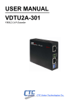
1
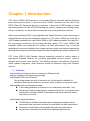
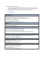
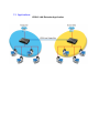
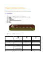
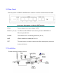
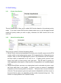
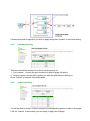
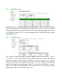
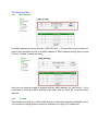
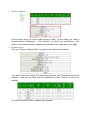
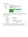
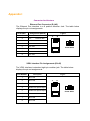
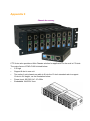
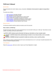
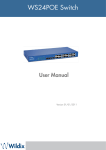
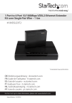
VDTU2A-304 VDSL2 Bridge LAN Extender with 4-Port Switch 3 Copyright by CTC Union Technologies Co., Ltd., all right reserved The information in this document has been checked carefully and is believed to be correct as of the date of publication. CTC Union reserves the right to make changes in the product of specification, or both, presented in this publication at any time without CTC Union assumes no responsibility or liability arising from the specification listed herein. We make no representations that the use of its products in the manner described in this publication will not infringe on existing or future patents, trademark, copyright, or rights of third parties. Implication or other under any patent or patent rights of CTC Union grants no license. All other trademarks and registered trademarks are the property of their respective holders. Version Revision Description 1.0 1.1 First Release Revise product figures (product picture, front, rear panel) Manual Version 1.1 April 2014 4 Corresponding version 1.0 1.0 Tables of Contents CHAPTER 1 INTRODUCTION................................................................................................................................. 7 1.1 FEATURES ...................................................................................................................................................... 7 1.2 SPECIFICATION ............................................................................................................................................... 8 1.3 APPLICATIONS ................................................................................................................................................ 9 CHAPTER 2 HARDWARE INSTALLATION .............................................................................................................. 10 2.1 FRONT PANEL ....................................................................................................................................................... 10 2.2 REAR PANEL ......................................................................................................................................................... 11 2.3 INSTALLATION ....................................................................................................................................................... 11 CHAPTER 3 CONFIGURATION VIA WEB BROWSER .............................................................................................. 12 3.1 5 PORTS SMART SWITCH WEB CONTROLLER LOGIN ..................................................................................................... 12 3.2 SYSTEM ............................................................................................................................................................... 14 3.2.1 Authentication Configuration ......................................................................................................................... 14 3.2.2 System IP Configuration ................................................................................................................................. 14 3.2.3 System Status ................................................................................................................................................. 14 3.2.4 Load Default Setting ....................................................................................................................................... 15 3.2.5 Firmware Upgrade .......................................................................................................................................... 15 3.2.6 Reset Device ................................................................................................................................................... 16 3.2.7 Config Backup/ Restore .................................................................................................................................. 16 3.3 PORT MANAGEMENT ............................................................................................................................................. 17 3.3.1 Port Configuration .......................................................................................................................................... 17 3.3.2 Flow Control Setting ....................................................................................................................................... 17 3.3.3 Port Mirroring................................................................................................................................................. 18 3.3.4 Bandwidth Control ......................................................................................................................................... 19 3.3.5 Broadcast Storm Control ................................................................................................................................ 20 3.3.6 CRC Counter ................................................................................................................................................... 20 3.4 VLAN................................................................................................................................................................. 21 3.4.1 Port base VLAN............................................................................................................................................... 21 3.4.2 Tag base VLAN ................................................................................................................................................ 22 3.5 QOS SETTING ....................................................................................................................................................... 23 3.5.1 Priority Classification ...................................................................................................................................... 23 3.5.2 Queue Scheduling Mode ................................................................................................................................ 23 3.5.3 Port-Based Priority ......................................................................................................................................... 24 3.5.4 VLAN Tag Priority ............................................................................................................................................ 24 3.5.5 TOS/DSCP Priority........................................................................................................................................... 25 3.5.6 TCP/UDP Priority ............................................................................................................................................ 25 5 3.6 SECURITY FILTER .................................................................................................................................................... 26 3.6.1 MAC ID Filter ...................................................................................................................................................26 3.6.2 Firewall............................................................................................................................................................26 3.7 VDSL SETTING...................................................................................................................................................... 28 3.7.1 Port Setting .....................................................................................................................................................28 3.7.2 Mode Select ....................................................................................................................................................28 APPENDIX I ....................................................................................................................................................... 29 Connector Architecture ...................................................................................................................................... 29 APPENDIX II ...................................................................................................................................................... 30 Chassis Accessory ............................................................................................................................................... 30 APPENDIX III FAQ.............................................................................................................................................. 31 DEFAULT IP ADDRESS ................................................................................................................................................... 31 DEFAULT LOGIN INFORMATION ....................................................................................................................................... 31 HOW TO RESET CTC UNION VDSL2 LAN EXTENDER ......................................................................................................... 31 APPENDIX IV TERMINOLOGY............................................................................................................................. 32 6 Chapter 1 Introduction CTC Union VDSL2 LAN Extender is a long reach Ethernet extender with four Ethernet ports and two phone jacks, in which one is for VDSL2 connection and the other is for POTS (Plain Old Telephone Service) connection. It has built-in POTS splitter to share the existing phone line with POTS eliminating the need for replacing the existing copper wiring. It is ideal for use as an Ethernet extender to an existing Ethernet network. Well accommodating VDSL2 (Very-high-data-rate Digital Subscribe Loop) technology to extend Ethernet service over single-pair phone line, CTC Union VDSL2 can reach up to 100/75 Mbps bandwidth (line rate) within 300M or 40/10 Mbps bandwidth (line rate) for 1 Km long-range connections. By providing ultra-high speed, CTC Union VDSL2 LAN Extender makes your telephone line achieve its best performance ever. It has the advantage of minimum installation time (simply as plug-n-play) and minimum expense by allowing video streaming and data to share the same telephone pair without interference. CTC Union VDSL2 LAN Extender delivers everything needed to quickly deploy a high-speed IP-based network for providing high-speed Internet access, video-on demand services and voice services. The resulting compact, cost-effective form factor offers systems integrators, small business owners an attractive long reach Ethernet solution. 1.1 Features Cost effective bridge function to connect two Ethernet LAN Easy installation via simple plug-and-play Selectable CPE and CO mode: Two working modes are built in the same unit, which keep the flexibility of installation and easy provision of service but lower inventory of service provider. Selectable fast and interleaved mode: Fast mode guarantees a minimum end to end latency less than 1 mS. Interleaved mode provides impulse noises protection for any impulse noise with duration less than 250uS. Interleaved mode has a maximum end to end latency of 10mS. Selectable target band plan: VDSL2 defines multiple band plans and configuration modes to allow asymmetric and symmetric services in same binder for data transmission. Symmetric is selected to provide better downstream performance. Asymmetric is selected to provide better upstream performance. 7 Selectable target SNR margin: It has the ability to select fixed SNR margin value on 9 dB or 6db. The systems will maintain the SNR margin at their value across all usable loop length. The higher SNR value gets better line quality, but lower performance. 1.2 Specification VDSL2 standards Compliant with ITU VDSL2 standard G.993.2 Annex A, Annex B and Annex C Support VDSL2 profile: 8a, 8b, 8c, 8d, 12a, 12b and 17a Band plan profile: symmetric (Plan 997) and asymmetric (Plan 998) Support fast and interleaved mode Target SNR Margin: 6dB and 9dB Built-in POTS splitter to share voice and data Management Web-based GUI for quick setup, configuration and management Firmware upgradable from Web LAN Filtering functions for MAC/IP/Port. QoS for Port/VLAN/DSCP/TCP-UDP Port number. Port Based VLAN & IEEE 802.1q VLAN Tagging Port configuration for Bandwidth/Duplex/Speed/Flow control/Broadcast storm. Connections Four RJ-45 connectors for Ethernet 10/100Mbps ports with auto MDX/MDIX One RJ-11 connectors for VDSL2 port, One RJ-11 connection for POTS connection Indicators General : PWR and SYS WAN(VDSL2) : CO, CPE, LINK and ALM LAN (Ethernet) : 1,2,3,4 LNK/ ACT Physical/Electrical Power: 100~240VAC (via power adapter) Power consumption: 9 watts maximum. Temperature: 0~45°C Humidity: 0%~95%RH (non-condensing) 8 1.3 Applications VDSL2 LAN Extender Application 9 Chapter 2 Hardware Installation This chapter shows the front panel and how to install the hardware. 2.1 Front Panel Please see the graphic below for the front panel: Front panel can be separated into six parts from left to right: (1) Power (2) System (3) Central Office (4) Customer Premises Equipment (5) Link (6) Alarm LED Status of VDSL2 LAN Extender: Blinking On Off Power On Power Off PWR SYS System Activated System Failed CO CO Mode On CPE CPE Mode On LINK Activity Connected Slow: Start Connection Fast: Data Transmit ALM Connection Error 10 2.2 Rear Panel The rear panel of VDSL2 LAN Extender is where all of the connections are made. Connectors Description of VDSL2 LAN Extender DC-IN Power adaptor inlet: Input voltage 12VDC Ethernet (1,2,3,4) Four Ethernet10/100BaseT auto-sensing and auto-MDI/MDIX for Ethernet ports(RJ-45) PHONE This interface is for connecting phone line (RJ-11). LINE VDSL2 interface for WAN port (RJ-11). RST The reset button, the button restore the default setting when press this button until reboot 2.3 Installation Please see the illustration below 11 Chapter 3 Configuration via Web Browser 3.1 5 Ports Smart Switch Web Controller Login There is no software required to install in order to access your web controller, and all you need is a browser. To login your management system, please open any browser, such as, Internet Explore, Firefox, etc., and go to “http://192.168.1.1” (If you had changed the IP address, please login into the modified IP address). Once you connect to your VDSL2 LAN Extender, you will be able to see a login page, please check the following figure, and then, login into the system with your user name and password. (Note: the default user name is “admin” and the corresponding password is “admin”.) 12 After you complete the login process, a main page will be shown as the following photograph. In this page, there are five square icons on the top-right side to show current port status. In addition, you can explore more management options on the left-hand side. Click on management options in order to manage your VDSL2 LAN Extender. Please check the following sections for more information on how to work with your VDSL2 LAN Extender. 13 3.2 System 3.2.1 Authentication Configuration You can change login name and password in this page. After accomplish your modification, please press “Update” button to save the change. 3.2.2 System IP Configuration “System IP Configuration” shows IP configuration, such as, IP address, subnet mask and gateway. In addition, you can change these settings in this page. (Note: please remember login this web controller with the IP address you saved!) 3.2.3 System Status “System Status” allow you to review hardware information and software version of your VDSL2 LAN Extender. “Update” button saves the information you provide in “Comment” field. 14 3.2.4 Load Default Setting “Load Default Setting” provides two methods to restore your VDSL2 LAN Extender ‘s information. 1. “Reserved IP”: this allows you to reload the default factory settings without changing your IP address. 2. “All”: this means all setups will be restored to the original settings including IP address. Once you make your choice, please click on “Load” button to activate this option. 3.2.5 Firmware Upgrade You will be able to update your VDSL2 LAN Extender’s firmware in this page. Please request the password from CTC Union if you need to upgrade VDSL2 LAN Extender’s firmware. 15 3.2.6 Reset Device This page provides a way to restart your VDSL2 LAN Extender without turn off and on your VDSL2 LAN Extender’s power. Click on “Confirm” in order to restart your VDSL2 LAN Extender. 3.2.7 Config Backup/ Restore For backup option, click on “Download” and a file explore will be popped up. Then, choose the location you wish to store this backup file. In order to recovery your VDSL2 LAN Extender, click on “Browse” button to choose which file to restore from, and then, please key in your password and click on “Update” to start restore process. 16 3.3 Port Management 3.3.1 Port Configuration You are able to setup port configurations in this page and check which port to apply these settings (check all ports to apply all ports with the settings in once.). Press “Submit” to take effect on the new settings. All information will be updated to the status table. 3.3.2 Flow Control Setting Two settings can be changed in “Flow Control Setting” page: backpressure and IEEE 802.3x Flow Control. Once you make your choice, please click “Submit” to save your choice. 17 3.3.3 Port Mirroring “Port Mirroring” page allows you to change mirror setups in two styles. “Change Mirror Mode” to change mirror setup style. Click on In order to accomplish port mirroring function, you need the following information. 1. Mirror Port: select a mirror port to monitor the traffic source. 2. Mirror Mode: Disable: port mirroring function is disabled. Rx: copy the incoming packets of the selected source port to the selected mirror port. Tx: copy the outgoing packets of the selected source port to the selected mirror port. Tx&Rx: copy both incoming and outgoing packets from the selected source port to the selected mirror port. Mirror source-destination pair: Tx port and Rx port must be the different port. 3. Source Port: the traffic source port which will be copied to the mirror port. 4. Destination Port: only available in mode 2. Mode 1 For mode 1, there are four options for “Mirror Mode”: Disable, Rx, Tx, and Tx&Rx. In this mode, all you need is setting up mirror port number, source port number, and mirror mode. Then, click on “Update” to save your change. 18 Mode 2 In mode 2, you can choose either “Disable” or “Mirror source-destination pair” for “Mirror Mode”. In addition, you need to choose destination port and source port. Please click on “Update” to save the settings after you finish your changes. 3.3.4 Bandwidth Control In “Bandwidth Control” page, choose the port you wish to set up bandwidth control, then, fill up Tx and Rx rates. Click on “Update” to load the settings you choose; otherwise, click on “Load Default” to restore the default value for the selected port. Once you update the settings, the table will show current setups for each port. 19 3.3.5 Broadcast Storm Control In this section, you will be able to block excessive broadcast packets. Choose which port you wish to start this protection. Enable “Broadcast Storm” option to execute this function and give a value for “Threshold”. Broadcast packets will be dropped when broadcast packets number is more than threshold value. 3.3.6 CRC Counter “CRC Counter” shows how many CRC error occurs during your VDSL2 LAN Extender is up. Click “Clear” to reset the counter and “Refresh” to update the latest counter information. 20 3.4 VLAN CTC Union VDSL2 LAN Extender provides two possible ways to set VLAN up, by Port base or by Tag base. If you choose to set up VLAN based on Port, the settings in Tag base will not be executed. 3.4.1 Port base VLAN You need to make sure “VLAN Mode” is correct. If not, click on “Change Mode” to switch VLAN mode. Choose “Port No” first, then, check which port should be in this VLAN member. Click on “Update” to save your changes, and click on “LoadDefault” to restore the default value. All information will be shown in the table. made are correctly displayed in the table. Please check whether the changes you just 21 3.4.2 Tag base VLAN Click on “Tag base VLAN” link on the left-hand side to switch to this page. If you see “VLAN Mode” is still “Port Base”, then, click on “Change Mode” to switch to the correct mode. In setup area 1, you can choose VLAN number, and which port you want to add or remove a tag. In addition, you check all the VLAN members you wish to have in this VLAN number. Click on “Submit” to save this change. (Note: a message box “Control port will not be able to connect devices” will be shown due to some receiver machine will not recognize VLAN tag so you may be not able to connect to a tagged port.) In setup area 2, you can set PVID of each port. If your PVID is invalid, a warning message “Invalid VLAN status” will be shown. For more information about VLAN tagging, please check Appendix IV. 22 3.5 QoS Setting 3.5.1 Priority Classification “Priority Classification” allow you to enable QoS function based on the selected priority mode. If you need to start QoS function, please make sure you visit this page first and enable the priority mode you wish to apply; otherwise, the QoS function will not be executed. 3.5.2 Queue Scheduling Mode There are two modes in “Queue Scheduling Mode”. 1. Strictly Priority: services queues based on priority only. As traffic comes into the EFM modem, traffic on the highest priority queue, Q3 is transmitted first. When that queue empties, traffic on the next highest-priority queue, Q2 transmitted until Q2 empties, and then traffic is transmitted on Q1 and so on. If higher priority queues never empty, then traffic on lower priority never gets sent. The SP class is typically for video applications that require a fixed amount of bandwidth to be considered good quality. 2. Weight-Round-Robin: services on a rotating basis and is activated only when a port has more traffic than it can handle. A queue is given an amount of bandwidth irrespective of the incoming traffic on that port. The queue then moves to the back of the list. The next queue is given an equal amount of bandwidth, and then moves to the end of the list, and so on, depending on the number of queues being used. This works in a looping fashion until a queue is empty. 23 Choose what kind of algorithm you wish to apply and press “Update” to save this setting. 3.5.3 Port-Based Priority Two items should be selected in order to set this priority up. 1. Port number: choose the port number you wish to apply this policy. 2. Queue number: choose which queue you wish the selected port belong to. Press “Submit” to execute this modification. 3.5.4 VLAN Tag Priority You will be able to assign VLAN priority and its corresponding queue number in this page. Click on “Submit” to save when you are ready to apply the changes. 24 3.5.5 TOS/DSCP Priority In this section, you can assign queue with a DSCP priority. Click on “Submit” and the information will be saved and updated to the table below. (Note: in order to allow QoS running TOS/DSCP priority, please make sure you change “Priority Classification” option to “TOS/DSCP Priority” first. For detail information about TOS/DSCP Priority, please check Appendix IV.) 3.5.6 TCP/UDP Priority First, choose “Logical Port Type” and press “Submit” and start this function. Then, if you want to run this priority based on pre-defined logical port, assign “Pre-defined Logical Port Number” entry and click on “Submit” to save the changes. If you want to activate this priority by user-defined logical port, you need to assign “User-defined Logical Port Range” section and press “Submit” to save your modifications. (Note: in order to allow QoS running TCP/UDP priority, please make sure you change “Priority Classification” option to “TCP/UDP Priority” first.) 25 3.6 Security Filter 3.6.1 MAC ID Filter Five MAC addresses can be stored in “MAC ID Filter”. Choose which entry number you wish to save this MAC and fill up its MAC address in “MAC Address setting” and its mode. Click on “Update” to save this entry. Now you can notice the table is updated with the MAC address you just saved. If you would love to remove all MAC address in the table, click on “Clear All” to remove every address. 3.6.2 Firewall This function provides you to filter traffic control or forward packets by bandwidth control. You are able to assign either a specific IP address or a range of IP addresses. 26 1. Specific IP address Choose which entry you wish to add this set of data. In this mode, you need to provide specific IP addresses. Click “Submit” if you finish your modification. The data you just saved should be updated into the table in the upper part of this page. 2. IP address range Click on “Change to Range Mode” to switch to the following edit section. You need to provide a range of IP address by filling up start IP address and end IP address. After you are done with the modification, press “Submit” to save your settings. The latest information will be updated into the table. 27 3.7 VDSL Setting 3.7.1 Port Setting In this section, you can change VDSL port settings. After you change the settings, click “Submit” to update your VDSL2 LAN Extender. Click “Refresh” to get the latest information of VDSL status. 3.7.2 Mode Select In “Mode Select” page, you can set your VDSL2 LAN Extender up as CO, central office, or CPE, customer premises equipment. Once you choose the mode, click “Submit” to save this change. (Note: this function will restart your VDSL2 LAN Extender.) 28 Appendix I Connector Architecture Ethernet Port Connector (RJ-45) The Ethernet Port interface is a 8 position Modular Jack. The table below displays the pin out assignments. Pin Number Assignment (MDI-X) 1 RX+; Receive data + 2 RX-; Receive data - 3 TX+; Transmit data + 4 Not used 5 Not used 6 TX-; 7 Not used 8 Not used Figure 1 8 1 8 Front View Transmit Data Top View VDSL Interface Pin Assignments (RJ-45) The VDSL interface is standard eight-pin modular jack. The table below displays the pin out assignments. Pin Number Description Figure 1 Not used 2 Not used 3 Not used 4 ANALOG Input/Output 5 ANALOG Input/Output 6 Not used 7 Not used 8 Not used 1 8 1 Front View Top View 29 8 Appendix II Chassis Accessory CTC Union also provides a Mini-Chassis solution for application on the rack in CO side. The major factor of FMC-CH08 is listed below: 2 U high Support 8-slot in one unit Two units of mini-chassis are able to fit into the 19-inch standard rack to support 16-slot in 2U height., as the illustration below Power Input: 90-230V AC, 47~63Hz Embedded 10A/230V fuse. 30 Appendix III FAQ Default IP Address Default IP address is “http://192.168.1.1”. Default Login Information Default login name is “admin” and the password is “admin”. How to Reset CTC Union VDSL2 LAN Extender There is a reset button on the back panel of VDSL2 LAN Extender. Please use a sharp item, such as, sharp pencil or paper clip, to press this button for couple seconds. This will reset all the configurations of CTC Union VDSL2 LAN Extender. You will be able to login this machine with the default login information and default IP address. Note: 1. Press this button for 2 seconds: reboot VDSL2 LAN Extender without reset any configuration. 2. Press this button for 8 seconds: load default factory configuration and reboot VDSL2 LAN Extender. 31 Appendix IV Terminology Term Meaning QoS Quality of Service Refers to resource reservation control mechanisms rather than the achieved service quality. QoS is the ability to provide different priority to different applications, users, or data flows, or to guarantee a certain level of performance to a data flow. (ref. 2) SNR Sigal-to-noise Ratio Is measure used in science and engineering to quantify how much a signal has been corrupted by noise. It is defined as the ratio of signal power to the noise power corrupting the signal. A ratio higher than 1:1 indicates more signal than noise. TOS/DSCP Type of Service/ Diffserv Codepoint This uses the upper six bits in the ToS (Type of Service) byte to mark priority traffic. Hence, there are 64 possible codepoints. VLAN Tagging VLAN tagging (IEEE 802.1A) is a networking standard written by the IEEE 802.1 work group allowing multiple bridged networks to transparently share the same physical network link without leakage of information between networks. VLAN tagging defines the meaning of a Virtual LAN (VLAN) with respect to the specific conceptual model underpinning bridging at the MAC layer and to the IEEE 802.1D spanning tree protocol. This protocol allows for individual VLANs to communicate with one another with the use of a switch with Layer-3 capabilities, or a router. (ref. 1) 32