1
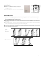
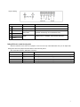
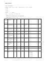
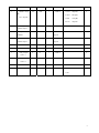
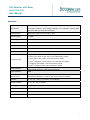
VOC Detector with Relay Model TON-0012 User Manual Specifications Combustion gas and odorous gases within the room (smoke, body odor, timber dope Gas detected and toluene emitted by other building materials), low concentration odorous gases (ammonia, H2S, CO, alcohol and natural gas) Sensing element Semiconductor gas sensor from Figero, Japan Measuring range 1~30ppm Power Supply 24VAC/VDC Consumption 2.5 W Load (for analog output) >5K Sensor query frequency Every 1s Warm up time 48 hours (first time), 10 minutes (operational) 1st green light on when VOC measurement≤5ppm 1st and 2nd green lights on when 5ppm<VOC measurement≤10ppm Six indicator lights 1st yellow light on when 10ppm<VOC measurement≤15ppm 1st and 2nd yellow lights on when 15ppm<VOC measurement≤20ppm 1st red light on when 20ppm<VOC measurement≤25ppm Modbus interface 1st and 2nd red lights on when VOC measurement>25ppm RS485 with 19200bps(default), 15KV antistatic protection, independent base address Output resolution 10Bit Relay output One dry contact output, rated switching current 2A, resistance load (Only for L101) The IAQ level selectable to control the relay action during four IAQ levels. Operation 0~50℃ (32~122℉) / 0~95%RH,non condensing Storage conditions 0~50 (32~122 ) /5~90%RH Net weight / Dimensions 190g /100mm×80mm×28mm Installation standard 65mm×65mm or 2”×4” wire box Housing PC/ABS fireproof material /IP30 protection class Version V.F026 1 Figure.2 Important Information 28.00 3.00 Always cut off power before mounting, removing, and 55.00 cleaning the indicator. 4.50 8.00 Notice the supply power voltage of the indicator is 24VAC/VDC 45.00 60.00 Mounting and Wire Connection Follows the step 1to step 4 in Figure1 to remove the cover. First, prepare a flat head screwdriver and cut off the power. Put the screwdriver deep inside of the hole on the top of the indicator. Then slant the screwdriver and open the cover gently following steps from step 2 to step 4. Mount the indicator on the place where you want to detect VOC level. Do not mount it near diffuser or any steam source, in direct sunlight. Mount the wall plate first, there are two dimensions available (see figure 2). Place the indicator against the wall at desired location; make sure wires can be passed through the notch on the wall plate. Connect wires to terminal strips, (see the label on the wall plate and fig.3) Make sure wiring connection correct and secure. Follows steps in figure 4 to close the cover. Figure.1 Open Cover 4 3 2 1 Figure.4 Close Cover 5 6 7 2 Figure.3 Wiring Connection Terminal Function Electrical Data 1 G+ Power (+) 24VAC/24VDC + 2 G0 Power ground (-) 24VAC/24VDC 3 Controlled device 4 Common Relay output <245VAC 2A switching current (resistance load) 5 B (RX-) 6 A (TX+) RS485 Modbus protocol, 19200bps, 15KV antistatic protection. Setting VOC level to control the relay action Open the indicator’s cover, there are 2 jumpers J1 and J2 on the top of the PCB board. Now you can adjust IAQ setting level via the two jumpers as below table to control the relay action. OFF means disconnection, ON means connection. Jumper setup IAQ setting level Relay on /off J1=OFF J2=OFF 5ppm The relay turns on when VOC>5.5ppm and turns off when VOC<4.5ppm J1=OFF J2=ON 10ppm The relay turns on when VOC>10.5ppm and turns off when VOC<9.5ppm J1=ON J2=OFF 15ppm The relay turns on when VOC>15.5ppm and turns off when VOC<14.5ppm J1=ON J2=ON 20ppm(Default) The relay turns on when VOC>20.5ppm and turns off when VOC<19.5ppm 3 Modbus Parameters Mode: RTU (MSB First) Baud Rate: 1-4800 Start Bits: 1 Data Bits: 8 Stop Bits: 1 / 2 Parity: None 3-14400 2-9600 4-19200 5-38400 bps default: 4-19200bps default : 1 / Odd / Even default: None MODBUS POLL-F2000TSM-VOC-L101C Register Map Support Starting Register Function: 2 3 4 Data 6 16 Functi Description on Read/Wr ite Lengt Format Valid Response h Defau lt Decimal 0 4 VOC R 2 Float big-end Measurement(Floa t) 2 Temperature 4 R 2 Measurement 4 big-end Humidity 4 R 2 Measurement 6 Float Float big-end VOC 4 R 1 INT16 4 R 1 INT16 4 R 1 INT16 3/6 R/W 1 UINT16 1~255 1 3/6 R/W 1 UINT16 1-4800bps 4 Measurement(INT 16)x10 7 Temperature Measurement(INT 16)x10 8 Humidity Measurement (INT16) 0 Modbus Address 1 Modbus Rate Baud 2-9600bps 3-14400bps 4-19200bps 4 5-38400bps 2 Modbus Parity 3/6 R/W 1 UINT16 Bit and Stop Bit 6 Humidity 3/6 R/W 1 3/16 R/W 2 UINT16 1-None 1Stop Bit; 2-None 2Stop Bit; 3-Odd 1Stop Bit; 4-Even 1Stop Bit 2 5~99 50 -3.0~3.0 0.0 0.1~30.0 15.0 Calibrate Object 10 Temperature Calibrate 38 Voc Float big-end Current 3/16 R/W 2 Calibrate Object Float big-end 0 0~10v/4~20mA 2 R 1 UINT16 0 1 Relay Setpoint 2 R 1 UINT16 0 2 R 1 UINT16 1 1 R 1 UINT16 Choice 1 2 Relay Setpoint Choice 2 0 Relay 0-OFF 1-ON Note:Scan Rate>=4000ms 5